Table of Contents
Advertisement
Quick Links
Advertisement
Table of Contents

Related Manuals for Zmotion EIO1616


Summary of Contents for Zmotion EIO1616
- Page 2 This manual is copyrighted by Shenzhen Technology Co., Ltd., without the written permission of the Zmotion Technology, no person shall reproduce, translate and copy any content in this manual. The above-mentioned actions will constitute an infringement of the copyright of the company's manual, and Zmotion will investigate legal responsibility according to law.
- Page 3 ⚫ Zmotion will not take any legal responsibility for personal safety accidents and property losses caused by failure to comply with the contents of this manual or illegal operation of products. Safety Level Definition According to the level, it can be divided into "...
- Page 4 ◆ Improper installation of the controller may result in misoperation, failure and fire. Wiring ◆ The specifications and installation methods of the external wiring of the equipment shall comply with the requirements of local power distribution regulations. ◆ When wiring, all external power supplies used by the system should be disconnected before operation.
-
Page 5: Table Of Contents
EIO1616 Bus Expansion Module User Manual V1.5 Content Chapter I Production Information..................2 1.1. Product Information ..................2 1.2. Function Features ....................2 1.3. System Frame ....................2 1.4. Hardware Installment ..................2 Chapter II Product Specification ..................5 2.1. -
Page 6: Chapter I Production Information
EIO1616 bus expansion module is used for EtherCAT bus controller, when IO and other resources are not enough, the controller can link with multiple EIO1616 through EtherCAT bus. And IO and axis resources of EIO1616 can be accessed by mapping No. 1.2. Function Features ◆... - Page 7 EIO1616 Bus Expansion Module User Manual V1.5 → Unit: mm → Mounting Hole Diameter 3.5mm Non-professionals are strictly prohibited to operate. Specifically, ⚫ professionals who had been trained related electrical equipment, or who master electrical knowledge. ⚫ Please be sure to read the product instruction manual and safety precautions carefully before installation.
- Page 8 EIO1616 Bus Expansion Module User Manual V1.5 places where the surrounding ambient temperature exceeds the range of -20° C-60° C places where the ambient humidity exceeds the range of 10%- 95% (non-condensing) places with corrosive gases and flammable gases places with many conductive powders such as dust and iron...
-
Page 9: Chapter Ii Product Specification
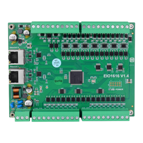
EIO1616 Bus Expansion Module User Manual V1.5 Chapter II Product Specification 2.1. Interface Definition Mark Interface Number Description IO Power state: it lights when IO power is IO POWER The led that indicates conducted. the current state. Main power state: it lights when main power POWER is conducted. -
Page 10: Order Information
EIO1616 Bus Expansion Module User Manual V1.5 of expansion module. 2.2. Order Information Model Functions EIO1616 Internal 16 digital inputs, 16 digital outputs EIO1616M Internal 16 digital inputs, 16 digital outputs, with module type EIO1616MT Internal 16 digital inputs, 16 digital outputs, with module cover type 2.3. -
Page 11: Chapter Iii Wiring, Communication Configuration & Ethernet
EIO1616 Bus Expansion Module User Manual V1.5 Chapter Wiring, Communication Configuration & Ethernet 3.1. Power Input The power supply input adopts a 3Pin (there are all 3 terminals) screw-type pluggable wiring terminal. IO power inputs are in digital IO outputs, power is supplied by 24V DC power. -
Page 12: Power Specification
EIO1616 Bus Expansion Module User Manual V1.5 3.1.1. Power Specification → Specification Item Main Power IO Power Voltage DC24V(-10%~10%) DC24V(-5%~5%) The current to open ≤0.5A The current to work ≤0.4A ≤0.5A Anti-reverse connection Valid Valid Overcurrent Protection Valid Valid 3.2. IN Digital Input →... -
Page 13: Digital Input Specification
EIO1616 Bus Expansion Module User Manual V1.5 3.2.1. Digital Input Specification Item Digital input (IN0-15) Input mode NPN type, input is triggered when in low-electric level Frequency <5kHz Impedance 4.7KΩ Voltage level DC24V The voltage to open <14.5V The voltage to close >14.7V... -
Page 14: Out Digital Output
EIO1616 Bus Expansion Module User Manual V1.5 supply system, this connection also can be omitted. 3.3. OUT Digital Output → Terminal Definition Terminal Name Type Function IOGND IO power ground IO24V IO power input DC24V OUT0 Output 0 OUT1 Output 1... -
Page 15: Digital Output Wiring
EIO1616 Bus Expansion Module User Manual V1.5 Voltage level DC24V Max output current +300mA Max leakage current when off 25μA Respond time to conduct 12μs Respond time to close 80μs Overcurrent protection Support Isolation method optoelectronic isolation Note: The times in the form are typical based on the resistive load, and may change when the load circuit changes. -
Page 16: Ethercat Bus Interface
3.4. EtherCAT Bus Interface EIO1616 bus expansion module has 2 100M EtherCAT communication interfaces, and they support EtherCAT protocol. EtherCAT 0 is connected to main controller or former level expansion module, but EtherCAT 1 is connected to drive equipment or next level expansion module, they can not be mixed. - Page 17 EIO1616 Bus Expansion Module User Manual V1.5 Transfer media Cable Transfer distance It is less than 100M between 2 nodes Process data Maximum 1486 bytes of one single frame Synchronization shaking <1us of two slave stations Refresh 1000 digital input and output about is 30us →...
-
Page 18: Expansion Module Usage
EIO1616 Bus Expansion Module User Manual V1.5 Please use tube-type pre-insulated terminals and cables with appropriate wire diameters to connect the user terminals. → Interface Indicator Led Definition Item Function Color Status Description OFF commonly MAC is not connected MAC has been connected and... - Page 19 EIO1616 Bus Expansion Module User Manual V1.5 The state value of the corresponding input port can be directly read through the "IN" command, and the state of the input port can also be visually checked through the "ZDevelop/View/IN" interface or the IO indicator light on the expansion module. For details, see "ZBasic Programming Manual".
-
Page 20: Chapter Iv Expansion Module
To prevent interference, the IO power supply is separated from the main power supply. After the EIO1616 expansion wiring is completed, each EIO expansion module does not need to develop again. It only needs to manually configure the unique IO address and axis address in the EtherCAT master controller, and it can be accessed after the configuration is completed. -
Page 21: Ethercat Bus Expansion Resource Mapping
EIO1616 Bus Expansion Module User Manual V1.5 slot number of the EtherCAT bus is 0. Device number (node): The device number refers to the number of all devices connected to a slot. It starts from 0 and is automatically numbered according to the connection sequence of the devices on the bus. - Page 22 EIO1616 Bus Expansion Module User Manual V1.5 If device 0 is EIO1616, after configuration according to the above syntax, the IO numbers corresponding to input IN0-15 are 32-47 in turn, and the IO numbers corresponding to the output OUT0-15 are 32-47 in sequence.
-
Page 23: Chapter V Run And Maintain
EIO1616 Bus Expansion Module User Manual V1.5 Chapter V Run and Maintain The correct operation and maintenance of the device can not only guarantee and extend the life cycle of the equipment itself, but also take technical management measures according to the pre-specified plan or the corresponding technical conditions to prevent equipment performance degradation or reduce the probability of equipment failure. -
Page 24: Common Problems
EIO1616 Bus Expansion Module User Manual V1.5 Should be within the range of Whether the device is subjected to vibration resistance vibration or shock impact resistance Keep good ventilation and Is the heat dissipation good heat dissipation The mounting screws should... - Page 25 EIO1616 Bus Expansion Module User Manual V1.5 Check whether IO power is needed. Check whether the limit sensor works normally, and whether the "input" view can watch the signal change signal can’t of the limit sensor. detected. Check whether the mapping of the limit switch is correct.
Need help?
Do you have a question about the EIO1616 and is the answer not in the manual?
Questions and answers