Table of Contents
Advertisement
Quick Links
Advertisement
Table of Contents

Subscribe to Our Youtube Channel
Summary of Contents for LACO Technologies ATLAS
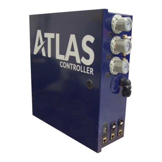
- Page 1 ATLAS LEAK TEST CONTROLLER OPERATIONS AND MAINTENANCE MANUAL...
- Page 2 3085 West Directors Row, Salt Lake City, UT 84104 | Phone: 801-486-1004 | info@LACOtech.com - www.lacotech.com...
- Page 3 Manual Name: ATLAS Helium Charge Controller Operations and Maintenance Manual Product Group: ATLAS Helium Charge Controller Manual Rev. Number: SMT-07-1025, Rev. D1 © 2023 LACO Technologies, Inc. No part of this manual may be reprinted, translated, or duplicated without the expressed written consent of LACO Technologies, Inc.
-
Page 5: Table Of Contents
Storage and Usage Conditions ................7 3.3. Unpacking, Handling, Shipping ................7 3.4. Decommissioning ....................7 3.5. Service for the Atlas Controller ................8 Equipment Description ......................9 4.1. Function of Equipment................... 9 4.2. Equipment Connections & Diagram ..............9 4.3. - Page 6 Maintenance and Spare Parts list ............... 57 8.2. Maintenance Documentation ................57 8.3. Maintenance Tools and Parts ................58 8.4. Opening Enclosure ....................58 Enclosure Door ..................58 8.5. Cleaning ........................58 External cleaning ..................58 ATLAS Operations and Maintenance Manual LACO Technologies...
- Page 7 Diaphragm Inspection ................63 Replacing Diaphragms ................65 Appendix..........................67 9.1. Recommended Default Parameters Settings ........... 67 9.2. ATLAS Remote Ethernet Protocol ..............67 Table 1. System States ................68 Table 2. Part States ................. 69 LACO Technologies ATLAS Operations and Maintenance Manual...
-
Page 9: About This Manual
Atlas versions. This manual is available for download at www.lacotech.com. These operating instructions are intended for customers of LACO Technologies and owners of an Atlas Leak Test Controller. All information in this operating manual applies to the current state of the products development. To access previous manual versions, contact LACO Technologies. -
Page 10: Safety
2 SAFETY Safety The ATLAS controller is designed to be used as a part of a leak test system to control the test process and provide an operator interface. In this configuration, it is dependent on other components (TITAN VERSA detector, tooling, etc.) The ATLAS can also be used as a stand-alone controller for helium charge only applications. -
Page 11: Operator Requirements
Operators, set-up operators, helpers or installation personnel should not alter, remove, or disable safety equipment. • The ATLAS must be operated according to the specification in this manual, otherwise the protective measures may be impaired. LACO Technologies ATLAS Operations and Maintenance Manual... -
Page 12: Dangers
• If equipped with an external part evac pump, there may be considerable vacuum suction at the part charging/evac connection. Take care to not allow debris, small objects, clothing, etc. to be sucked-up by the controller. ATLAS Operations and Maintenance Manual LACO Technologies... -
Page 13: Dangers From Liquids And Vapors
If these gases are measured with the device, the cathode layer of the ion source may be attacked. This may result in the burning out of the leak detector filament cathode. LACO Technologies ATLAS Operations and Maintenance Manual... -
Page 14: Equipment Safety Practices
If the indicator on the screen remains illuminated, then one or more faults are still active. CAUTION: Risk of injury when carrying the Atlas controller . Process or system faults do not remove hazardous voltage from the system. -
Page 15: Scope Of Delivery, Transport, Storage
Store and operate the ATLAS per the table located in section 4.3.1. The device can be disposed of by the user or sent to LACO Technologies for disposal. The device is made of recyclable materials. Use this option to avoid waste and to protect the environment. -
Page 16: Service For The Atlas Controller
3 SCOPE OF DELIVERY, TRANSPORT, STORAGE LACO Technologies offers first-class service of your Atlas Controller and associated equipment (TITAN VERSA), including: • On-site maintenance. • Overhaul and repair at the Salt Lake City Service Center • Fast device replacement with refurbished exchange products in exceptional condition •... -
Page 17: Equipment Description
4 EQUIPMENT DESCRIPTION Equipment Description The ATLAS controller is designed to be used as a part of a leak test system to control the test process and provide an operator interface. In this configuration, it is dependent on other components (TitanTest leak detector, tooling, etc.). -
Page 18: Test Performance Specifications
Ethernet & USB (Scanners, USB Drives, and serial by converter) Data Logging Test Summary and Stream csv files. Test Recipes 100 custom test recipes Remote IO Ethernet IP based Test Sequences Easily customizable to customer testing needs ATLAS Operations and Maintenance Manual LACO Technologies... -
Page 19: Installation
Installation The ATLAS can be intergrading multiple ways, below are examples. System Mounting ATLAS intergrade within system will be located on the left side of the Titan Versa assembly cart (TV121015). Bottom Mounting The ATLAS enclosure is equipped with (4) 1/4-20 threaded inserts located on the bottom. -
Page 20: Utilities Summary
Air Fill Regulator Control Air Fill Regulator Helium Fill Regulator Tooling Pneumatic Output (Optional) (4) 5/32” OD tube Electrical Wire Feedthrough (2) 1/2 CGB Remote IO DB-15 USB Port (2) Ethernet Port (3) RJ-45 ATLAS Operations and Maintenance Manual LACO Technologies... - Page 21 5 INSTALLATION LACO Technologies ATLAS Operations and Maintenance Manual...
-
Page 22: Gas Connections
Part Vent Outlet Connect a vent tube to the part vent connection on the ATLAS. This line should be plumbed away from the controller at least 15 feet (5m). Also, it is preferable to run the vent line vertical, to ensure the lighter helium gas does not increase the helium background near the test area. -
Page 23: Control Air Regulator
Connect the device to the electric power supply using the supplied power cable. Electrical interface connections are located on the right side of all ATLAS configurations. Section 5.2 utilities, all the interfaces, connection specifications, parts, and accessories used with each connection. -
Page 24: Operation
NOTICE: Risk of seizing Never move the controller while the unit is powered on, even if it is placed on a moveable cart. Each time before powering on the ATLAS: • Become familiar with the safety instructions (see •... -
Page 25: Power-On Process
RUN Light on the PLC will turn amber. After startup is complete, the test screen appears, and the RUN light on the PLC turns green. The Atlas can be powered off at any time by turning off the switch on the power entry module. LACO Technologies... -
Page 26: User Interface Features
Upper-middle – Status text or screen name. Note that status text is also displayed on the bottom of the screen. • Upper-right – Status icons. • Right-side menu on test screens for Quick-Access features . ATLAS Operations and Maintenance Manual LACO Technologies... -
Page 27: Screen Type Navigation
(see Table 2 below). Status Icon Summary Function Icon Description Operator Login – Not set up by default. If configured, the Login Level base user has very limited access to change parameters. LACO Technologies ATLAS Operations and Maintenance Manual... -
Page 28: User Access Levels
User Access Levels The ATLAS employs three user access levels: Operator, Technician, and Advanced. User levels are enabled by pressing the login level icon, then entering the correct password. Table 3 below summarizes the main features of each user level. - Page 29 Change Technician level password* *When logged on as Advanced, the Technician level password can be changed by entering 2 identical 4-digit numbers and pressing CHANGE. This option is not displayed when at Technician or Operator level. LACO Technologies ATLAS Operations and Maintenance Manual...
-
Page 30: Screen Menu Structure
6 OPERATION Screen Menu Structure Screen Menu Structure Start Up Shut Down Test Test Graph Test ID Test ID Setup Test Calibration System Settings Maintenance Advanced ATLAS Operations and Maintenance Manual LACO Technologies... -
Page 31: Software Screens And Parameter Settings
The main menu can be accessed by pressing the SETTINGS icon located on the upper-left of test screen. It provides access to four settings pages: • Advanced • Test • Maintenance • System • Calibration Advanced Settings Screen LACO Technologies ATLAS Operations and Maintenance Manual... - Page 32 6 OPERATION There are a total of nine advanced settings screens. They define the test type and application of the Atlas controller, as well as other operational parameters. Use extreme caution when using advanced settings. Inadvertent changing of advanced settings can make the ATLAS controller inoperable or cause unsafe conditions.
- Page 33 After the pressure has reached the setpoint, the settle delay timer allows for the pressure to equalize before evaluating if the pressure is still in tolerance. This settle timer applies to both fill and evac operations. LACO Technologies ATLAS Operations and Maintenance Manual...
- Page 34 This feature limits the exposure the leak detector helium contamination and ensure subsequent “good” parts will not give a false fail due to high helium background in the leak detector. ATLAS Operations and Maintenance Manual LACO Technologies...
- Page 35 The length of time waited before setting the background to zero. Use Ethernet for Comms Use Ethernet instead of serial cable to communicate with leak detector. LD IP Enter the IP address of the leak detector. 6.5.2.4. Clamp/Automation Settings LACO Technologies ATLAS Operations and Maintenance Manual...
- Page 36 Indicates that the system has safety control components (light curtains, emergency stop switches, etc.) Part Present Sensor Indicates that there is a part present sensor installed and connected to the ATLAS. Chamber Closed Sensor Indicates that there is a chamber door closed sensor installed and connected to the ATLAS.
- Page 37 Select if the part pressure and part evac will be sensed with the same transducer (absolute transducer). Part Pressure Unit Select the part pressure unit. Part Evac Unit Select the part evac pressure unit. Chamber Vacuum Unit Select the chamber vacuum pressure unit. LACO Technologies ATLAS Operations and Maintenance Manual...
- Page 38 Used to record 3 different pressure readings from an external pressure transducer to calculate the gain and offset for the transducer being calibrated. Gain/ Offset Show the calculated gain (slope) and offset (intercept) of the selected transducer. ATLAS Operations and Maintenance Manual LACO Technologies...
- Page 39 Insert Insert a new row to the row number specified. Delete Delete the selected row. Export SD Export the test sequence to the SD card. LACO Technologies ATLAS Operations and Maintenance Manual...
- Page 40 Enter the minimum pressure of the electronic regulator. Max Pressure Enter the maximum pressure of the electronic regulator. Output Behavior Choose the output behavior of the regulator from the three options: • Direct • • Custom ATLAS Operations and Maintenance Manual LACO Technologies...
-
Page 41: Maintenance
The data tables in the controller can also be exported or imported on the same screen. To do that, choose the data table wished to export/ import, then press the export or import button. LACO Technologies ATLAS Operations and Maintenance Manual... - Page 42 The manual mode screen allows user to manually turn on/ off each of the valves in the controller. Turn on the valve by pressing the red circle (representing a closed valve) and turn off the valve by pressing the green circle (representing an opened valve). ATLAS Operations and Maintenance Manual LACO Technologies...
-
Page 43: System Screen
The fault history screen shows the date, time, and message of the 20 most recent faults that occur in the system. See Section 7 for a complete list of faults and fault handling. System Screen There are four sub-screens under the system configuration menu. LACO Technologies ATLAS Operations and Maintenance Manual... - Page 44 IO buttons are used in the system. Language Select Choose the language of the controller. Default Test Screen Choose the test screen type from the three options: • Basic • Detail • Graph 6.5.4.2. Change Password ATLAS Operations and Maintenance Manual LACO Technologies...
-
Page 45: Recipe
Password” sections. If the new password entered on both sections match, a “Change” button will appear to allow for change of operator password. The Atlas manual and system manual screens contain a pdf file viewer for user to read the respective manuals. - Page 46 The length of time to run the test. Background Fault Time Background Fault Timer: Set this time for the maximum time allowed to reach the background limit during the background check before faulting a cycle. ATLAS Operations and Maintenance Manual LACO Technologies...
- Page 47 Continue after Timer End Check the box if wish to continue to let the test run even after the fine leak test is completed. Capture Data Enable data logging features. Capture Interval Test data sampling time. LACO Technologies ATLAS Operations and Maintenance Manual...
-
Page 48: Calibration Settings Screens
Set the air purge sequence run time. Sequence Delay Time Set the delay time before running each sequence. Calibration Settings Screens NOTICE: Calibration Frequency All Calibrations as-shipped settings will be recorded and provided in the accompanying As-Shipped Parameter Summary. ATLAS Operations and Maintenance Manual LACO Technologies... - Page 49 QCal Final The leak rate reading using the default Cal factor at the end of a calibration. Cal Factor Resets the Cal Factor to the Default Cal Factor. LACO Technologies ATLAS Operations and Maintenance Manual...
-
Page 50: Data Log Settings Screen
Test Stream & Sum – Logs data during the test and then a summary at the end of the cycle. • Data Log Interval – Sets the log interval to write data to the SD card during the data stream options. ATLAS Operations and Maintenance Manual LACO Technologies... -
Page 51: User Data Logging
Test ID Fields. • Enter the category NAME or description in the Test ID Fields column (e.g., Lot, S/N, Operator). • Check the box in the Required Column if the field cannot be left blank. LACO Technologies ATLAS Operations and Maintenance Manual... -
Page 52: Operation And Calibration
Enter the required data by selecting the proper box and using the optional barcode scanner or the onscreen keyboards. If the ATLAS controller is equipped with a barcode scanner, then scanning a barcode will enter the contents into the currently selected box. - Page 53 (CF) is stored (See section 6.5.6). 6.6.1.2. Running automated Tests Once the ATLAS has been calibrated, part leak testing can occur. To run an automated test cycle: 1. Verify the cal button is disabled to enable auto test mode.
-
Page 54: Sniffing Operation
6.6.2.2. Running Automated Tests Once the ATLAS system has been calibrated, part leak testing can occur. To run an automated test cycle: 1. Make all appropriate connections from the ATLAS to the part to be tested. ATLAS Operations and Maintenance Manual... - Page 55 During the sniff test, the ATLAS will store and display the peak leak rate value that is observed. To clear this value at any time during the test the operator can press the Clear Peak Value icon at the bottom left of the test screen.
-
Page 56: Helium Bombing Operation
Running Bombing Cycles 1. Load parts into bombing chamber and secure lid. 2. Verify the bombing chamber is connected to the outlet of the Atlas controller. 3. Select the desired recipe number and press the green start button to start the cycle. -
Page 57: Volume Evac Operation
(refer to section 6.6.3 for operation process). The right side is for the volume evac process. The leak detector will enter test mode once the Atlas startup is completed. Once the inlet pressure reaches a the setpoint, the screen will show the “Ready to Test”... - Page 58 5. The same test data will be shown during the fine leak test. 6. The test sequence will automatically reset upon the completion of the fine leak test. Allow time for system to process. 7. Start the next test as prompted. ATLAS Operations and Maintenance Manual LACO Technologies...
-
Page 59: Part Status And System States
Test In Progress Part Helium Fill Process Complete Leak Test Leak Test Calc Stop Titan Cycle Chamber Vent Part Cleanup Part Air Purge Unclamp/Open Sniff Test in Progress Sniffer Calibration Vent Pump Bombing in Progress LACO Technologies ATLAS Operations and Maintenance Manual... -
Page 60: Troubleshooting
Make sure LD Startup startup within the given Time setting is > 5 min. amount of time. • Check the leak detector screen for faults/warnings and refer to the Titan Versa Operators Manual. ATLAS Operations and Maintenance Manual LACO Technologies... -
Page 61: Process Faults
Versa screen and refer to the Titan Versa Operator Manual for information on how to resolve the issue. LD Com Error The ATLAS has lost RS232 • Check RS232 wiring communications with the between ATLAS and Titan Versa leak detector. - Page 62 The pressure inside the • Adjust the fill part did not reach the regulator. Air Fill Fault designated fill pressure. • Increase the fill time in the recipe. • Verify the fill pressure in the recipe. ATLAS Operations and Maintenance Manual LACO Technologies...
- Page 63 Verify that the sniffer Fault not able to evacuate the probe is connected sniffer probe and achieve properly. the necessary vacuum • Inspect the sniffer pressure for sniffing. probe and hose for tears/brakes. LACO Technologies ATLAS Operations and Maintenance Manual...
- Page 64 7 TROUBLESHOOTING Fault Description Fault Causes Fault Troubleshooting LD Failed to Start Cal The ATLAS was unable to • Check communication initiate a calibration cycle cables between ATLAS in the Titan Versa. and Titan Versa. Calibration Failed The measured leak rate is •...
-
Page 65: Maintenance And Spare Parts
Oil Mist Eliminator filter As Needed cartridge Maintenance documentation for the ATLAS is contained in this manual section and on the ATLAS USB drive. The following manuals are on the USB drive, under the “Maintenance Folder”. • Pump manual, UNO 6 •... -
Page 66: Maintenance Tools And Parts
Cleaners with alcohol or harsh chemicals will strip the enclosure paint. DANGER: Life threatening hazard from electric shock Incorrectly secured products may be life threatening. • Only use fuses with the prescribed values. ATLAS Operations and Maintenance Manual LACO Technologies... -
Page 67: Electrical
Locate fuse holder terminal bock and use hand to swing to open position. • Open fuse terminal block fuse compartment to reveal defective use and replace (3.0 AT, 250 V, Ø5 x 20mm). LACO Technologies ATLAS Operations and Maintenance Manual... -
Page 68: Power Cords
LACO recommends changing the pump oil if the oil color appears to be heavily discolored or white in appearance. ATLAS Operations and Maintenance Manual LACO Technologies... -
Page 69: Accessing Uno6 Pump
Twist top half of OME to remove cover. • Remove bolt on top of filter. Be sure to keep O-ring under bolt attached to the bolt. • Replace filter element. • Lightly oil all O-rings with pump fluid. LACO Technologies ATLAS Operations and Maintenance Manual... -
Page 70: Pump Repair Options
36000 hours or 72 OS or Replace pump PFPKD07553 months Other Pump Parts Part Number Description LMSA119457 UNO 6 hose assembly LMK-TVT-7 UNO 6 oil drain line LMK-TVT-8 UNO 6 oil fill line ATLAS Operations and Maintenance Manual LACO Technologies... -
Page 71: Dry Pump Maintenance
If the valve seals stick to the housing cover, carefully loosen the seals. Otherwise, remove the valve seal from the head covers. • Replace damaged valve seals. • Remove head cover. • Either clean all parts and inspect for wear or install new diaphragm. LACO Technologies ATLAS Operations and Maintenance Manual... - Page 72 8 MAINTENANCE AND SPARE PARTS ATLAS Operations and Maintenance Manual LACO Technologies...
-
Page 73: Replacing Diaphragms
• Reassemble the diaphragms in reverse order. • Install the new diaphragm between diaphragm clamping disk with square head screw and diaphragm support disk. Ensure the square head screw of the LACO Technologies ATLAS Operations and Maintenance Manual... - Page 74 8 MAINTENANCE AND SPARE PARTS diaphragm clamping disk is correctly seated in the guide hole of the diaphragm support disk. See picture below. • Reassemble pump in reverse order. ATLAS Operations and Maintenance Manual LACO Technologies...
-
Page 75: Appendix
Connect an ethernet cable to the RJ45 port on the right side of the unit and using a TCP Client terminal such as PuTTY or Hercules, connect to the ATLAS CPU IP address (located in UniApps -> Network) on port 20263. - Page 76 12 Stop Titan Cycle Air Purge 13 Chamber Vent Open Inner Weld 14 Part Cleanup Close Inner Weld 15 Part Air Purge Open Outer Weld 16 Unclamp/Open Close Outer Weld 99 End Sequence ATLAS Operations and Maintenance Manual LACO Technologies...
- Page 77 23 He Pres. Low Fault Part Unclamp Fault 24 Air Fill Pres. Low Fault Chamber Open Fault 25 Leak Detector Startup Fault Chamber Close Fault 26 Leak Detector Not Ready Fault Air Fill Fault LACO Technologies ATLAS Operations and Maintenance Manual...
Need help?
Do you have a question about the ATLAS and is the answer not in the manual?
Questions and answers