
Related Manuals for Banner R-GAGE Q90R


Summary of Contents for Banner R-GAGE Q90R
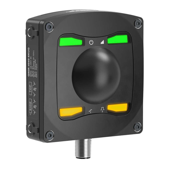
- Page 1 Q90R R-GAGE® Radar Sensor Instruction Manual Original Instructions p/n: 237883 Rev. A February 12, 2024 © Banner Engineering Corp. All rights reserved.
-
Page 2: Table Of Contents
7.1 Configuration Tool....................................27 Chapter 8 Product Support 8.1 Update the Software....................................29 8.2 Repairs ........................................29 8.3 Contact Us ......................................30 8.4 Banner Engineering Corp. Software Copyright Notice .......................... 30 8.5 Banner Engineering Corp Limited Warranty............................30 Index ............................31... -
Page 3: Chapter 1 Product Description
FMCW radar detects moving and stationary objects • Adjustable sensing field—ignores objects beyond setpoint • Easy setup and configuration of range, sensitivity, and output using the Banner Radar Configuration Software • Sensing functions are immune to wind, fog, steam, and temperature changes and resistant to rain and snow •... -
Page 4: Features And Indicators
• Easily monitor device status via the software • Visualize the application in real-time • Make adjustments to sensor settings on the fly For more information, visit www.bannerengineering.com/us/en/products/sensors/software/ radar-configuration.html. February 12, 2024 © Banner Engineering Corp. All rights reserved. -
Page 5: Chapter 2 Installation Instructions
(2) 4-20 mA A_Out 0-10 V A_Out gy (5) gy (5) Input Input * Push-Pull output. User-configurable PNP/NPN setting. * Push-Pull output. User-configurable PNP/NPN setting. Continued on page 6 February 12, 2024 © Banner Engineering Corp. All rights reserved. -
Page 6: Mount The Device
Input * Push-Pull output. User-configurable PNP/NPN setting. ** Pulse Frequency Modulation NOTE: Banner recommends that the shield wire (quick-disconnect cordsets only) be connected to earth ground or dc common. Shielded cordsets are recommended for all quick-disconnect models. Mount the Device If a bracket is needed, mount the device onto the bracket. -
Page 7: Chapter 3 Getting Started
Navigate to and open the downloaded file. Click Install to begin the installation process. Depending on your system settings, a popup window may appear prompting to allow Banner Radar Configuration to make changes to your computer. Click Yes. Click Close to exit the installer. -
Page 8: Software Overview
Q90R R-GAGE® Radar Sensor Instruction Manual Software Overview Easy setup and configuration of range, sensitivity, and output using the Banner Radar Configuration software and Pro Converter Cable. Figure 6. Banner Radar Configuration Software Navigation toolbar—Use this toolbar to connect to the sensor, to save or load a configuration, or to reset to factory defaults Live Sensor Data and Legend—Shows the signal strength versus distance for the connected sensor, as well as... -
Page 9: Chapter 4 Banner Radar Configuration Workspace
Use the Y-Axis Max and the X-Axis Max to adjust the range displayed on the plot. Legend -- Use the legend to select which data appears on the graph. Signal Displays the strength of the signal over distance. Signal Threshold Displays the signal strength threshold. February 12, 2024 © Banner Engineering Corp. All rights reserved. -
Page 10: Summary Pane
Strongest Target—Output responds to the target with the highest signal strength that is over the signal strength threshold. Nearest Target—Output responds to the nearest target that is over the signal strength threshold. February 12, 2024 © Banner Engineering Corp. All rights reserved. -
Page 11: Analog Tab
Define the outer limits of the analog range. This can be used to create a positive or negative slope. Analog output options: Current: 4 mA to 20 mA Voltage: 0 V to 10 V or 0.5 V to 4.5 V February 12, 2024 © Banner Engineering Corp. All rights reserved. -
Page 12: Discrete 1 Tab
Window: Define two setpoints to create window limits. Complementary: Output 2 will be the opposite of Output 1. Pulse Pro/PFM: Pulse Pro/PFM output to interface with Banner lights or a PLC with PFM inputs. February 12, 2024 © Banner Engineering Corp. All rights reserved. -
Page 13: Live Sensor Data Controls
50 Hz or 650 Hz (user defined in the software) represents a loss of signal condition where there is no target or the target is out of range. This output can be tied directly to a number of Banner lights for visual feedback without the need for a controller. -
Page 14: Using Measurement Hold Example
Output Measurement (green lines) holds its value for the Hold Time. After the 1 second Hold Time expires, the Output Measurement and Max Distance Change thresholds are updated based on the next Raw Measurement value. February 12, 2024 © Banner Engineering Corp. All rights reserved. -
Page 15: Chapter 5 Configuring A Sensor
IO-Link Master requires. Each IO-Link Master AOI is customized for a given brand of IO-Link Master. Add and configure the relevant Banner IO-Link Master AOI in your ladder logic program first; then add and configure Banner IO-Link Device AOIs as desired, linking them to the Master AOI as shown in the relevant AOI documentation. - Page 16 Q90R R-GAGE® Radar Sensor Instruction Manual The remote input wire is disabled by default. Pulse the remote input wire 10 times or use the Banner Radar Configuration software to enable the feature. After enabling the remote input feature, pulse the remote input according to the diagram and the instructions provided in this manual.
- Page 17 SPt Object Teach Window Teach Sensitivity Selection Speed Selection Fast Medium Slow Target Selection Mode Nearest Target Strongest Target Enable/Disable LEDs LEDs Enabled LEDs Disabled Reset to Factory Defaults Enable/Disable Remote Teach February 12, 2024 © Banner Engineering Corp. All rights reserved.
-
Page 18: Remote Teach
Q90R R-GAGE® Radar Sensor Instruction Manual NOTE: If a factory reset is performed through the Banner Radar Configuration Software, the remote input wire becomes disabled (factory default setting). If the sensor is returned to factory defaults by using the remote input wire, the input wire remains enabled and the rest of the settings are restored to factory defaults. -
Page 19: Discrete Teach Modes
Use Speed Selection to set the speed of the sensor. Access Speed Selection. Action Result Four-pulse the remote input. The green power LED flashes slowly. Select the desired signal threshold. February 12, 2024 © Banner Engineering Corp. All rights reserved. -
Page 20: Target Selection Mode
To reset using the Banner Radar Configuration software, go to Sensor › Factory Reset. The sensor indicators flash once, the sensor is reset back to the factory default settings, and a confirmation message displays. - Page 21 Discrete 2Tab Default Settings Setting Factory Default Output Mode Switch Point Setpoint 1 20.0 m (65.6 ft) Hysteresis 0.05 m (2 in) NO/NC Normally Open On Delay 0 ms Off Delay 500 ms February 12, 2024 © Banner Engineering Corp. All rights reserved.
-
Page 23: Chapter 6 Specifications
Pulse Frequency Modulated (PFM) output Repeatability 2 mm 10 mm at Excess Gain < 10× Maximum Transmitting Power Peak EIRP: 100 mW, 20 dBm Output Protection Protected against output short-circuit February 12, 2024 © Banner Engineering Corp. All rights reserved. -
Page 24: Fcc Part 15 Class A For Intentional Radiators
L’exploitation est autorisée aux deux conditions suivantes: L’appareil ne doit pas produire de brouillage. L’utilisateur de l’appareil doit accepter tout brouillage radioélectrique subi, même si le brouillage est susceptible d’en compromettre le fonctionnement. February 12, 2024 © Banner Engineering Corp. All rights reserved. -
Page 25: Dimensions
Use the Beam Width versus Degrees chart to help determine how much the target can tilt from 90 degrees while still maintaining detection. Unless otherwise specified, the following beam patterns are shown with Signal Strength Threshold = 1. February 12, 2024 © Banner Engineering Corp. All rights reserved. - Page 26 Car (Radar cross section = 1.5 m 2 ) Car (Radar cross section = 1.5 m 2 ) Metal Test Rod (90 mm) Metal Test Rod (90 mm) Distance (m) Distance (m) February 12, 2024 © Banner Engineering Corp. All rights reserved.
-
Page 27: Chapter 7 Accessories
Q90R R-GAGE® Radar Sensor Instruction Manual Chapter Contents 7.1 Configuration Tool ......................................27 Chapter 7 Accessories Configuration Tool PRO-KIT Includes: • Pro Converter Cable (MQDC-506-USB) • Splitter (CSB-M1251FM1251M) • Power Supply (PSW-24-1) February 12, 2024 © Banner Engineering Corp. All rights reserved. -
Page 29: Chapter 8 Product Support
Repairs Contact Banner Engineering for troubleshooting of this device. Do not attempt any repairs to this Banner device; it contains no field-replaceable parts or components. If the device, device part, or device component is determined to be defective by a Banner Applications Engineer, they will advise you of Banner's RMA (Return Merchandise Authorization) procedure. -
Page 30: Contact Us
Banner minimum systems requirements. The above limitations apply even if Banner and its affiliates and channel partners have been advised of the possibility of such damages. This Agreement sets forth the entire liability of Banner, its affiliates and your exclusive remedy with respect to the software use. -
Page 31: Index
IO-Link Sensor Settings software lockout sensor polarity sensor lockout minimum active sensing range maximum active sensing range TEACH modes measurement hold target selection maximum distance increase maximum distance decrease analog © Banner Engineering Corp. - Page 32 LinkedIn Twitter Facebook © 2024. All rights reserved. www.bannerengineering.com...
Need help?
Do you have a question about the R-GAGE Q90R and is the answer not in the manual?
Questions and answers