
Related Manuals for Banner R-GAGE Q90R2 Series


Summary of Contents for Banner R-GAGE Q90R2 Series
- Page 1 Q90R2 R-GAGE® Radar Sensor Instruction Manual Original Instructions p/n: 240867 Rev. A May 14, 2024 © Banner Engineering Corp. All rights reserved.
-
Page 2: Table Of Contents
Configuration Tool......................................27 Cordsets ........................................27 Brackets........................................28 IO-Link Masters ......................................29 Chapter 8 Product Support Update the Software....................................30 Repairs ........................................30 Contact Us ........................................31 Banner Engineering Corp. Software Copyright Notice ..........................31 Banner Engineering Corp Limited Warranty..............................31 ... -
Page 3: Chapter 1 Product Description
• FMCW radar detects moving and stationary objects • Adjustable sensing field—ignores objects beyond setpoint • Easy setup and configuration using the Banner Measurement Sensor Software • Sensing functions are immune to wind, fog, steam, and temperature changes and resistant to rain and snow •... -
Page 4: Overview
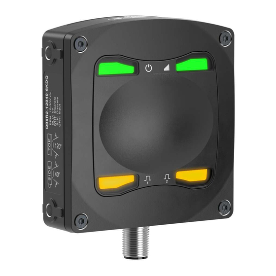
Features and Indicators Color Description Power Green Power ON Signal Strength Green Signal strength indication Output 1 Amber Discrete output 1 status Output 2 Amber Discrete output 2 status page 4 May 14, 2024 © Banner Engineering Corp. All rights reserved. -
Page 5: Banner Measurement Sensor Software
• Easily monitor device status via the software • Visualize the application in real-time • Make adjustments to sensor settings on the fly For more information, visit www.bannerengineering.com/us/en/products/sensors/software/ banner-measurement-sensor-software.html. May 14, 2024 page 5 © Banner Engineering Corp. All rights reserved. -
Page 6: Sensor Orientation
Input * Push-Pull output. User-configurable PNP/NPN setting. ** Pulse Frequency Modulation NOTE: Banner recommends that the shield wire (quick-disconnect cordsets only) be connected to earth ground or DC common. Shielded cordsets are recommended for all quick-disconnect models. May 14, 2024 page 6... -
Page 7: Mount The Device
Mount the device (or the device and the bracket) to the machine or equipment at the desired location. Do not tighten the mounting screws at this time. Check the device alignment. Tighten the mounting screws to secure the device (or the device and the bracket) in the aligned position. May 14, 2024 page 7 © Banner Engineering Corp. All rights reserved. -
Page 8: Chapter 3 Getting Started
Navigate to and open the downloaded file. Click Install to begin the installation process. Depending on your system settings, a popup window may appear prompting to allow the Banner Measurement Sensor software to make changes to your computer. Click Yes. -
Page 9: Software Overview
Q90R2 R-GAGE® Radar Sensor Instruction Manual Software Overview Easy setup and configuration using the Banner Measurement Sensor software and Pro Converter Cable. Banner Measurement Sensor Software Navigation toolbar—Use this toolbar to connect to the sensor, to save or load a configuration, or to reset to factory defaults Live Sensor Data—... -
Page 10: Chapter 4 Banner Measurement Sensor Workspace
The active sensing range correspond to the color of each output window and are hidden by default. Use Distance Max to adjust the range and field of view displayed on the 2D Scatter tab. May 14, 2024 page 10 © Banner Engineering Corp. All rights reserved. -
Page 11: Spectrum Tab
Displays whether the output is ON or OFF. Distance Displays the distance to the target, in meters. Velocity Displays the velocity of the target relative to the sensor, in meters per second. May 14, 2024 page 11 © Banner Engineering Corp. All rights reserved. -
Page 12: Sensor Settings Pane
Maximum Distance Decrease: The allowed limit the measurement can decrease, or move closer to the sensor, before initiating the Measurement Hold. Setting this to zero disables it. Available when Measurement Hold is set to enabled. Sensor Polarity Define the output and remote input signal type. Sensor Lockout Remote Input (Gray Wire): Enable or disable the remote input wire. Indication Enable or disable the Status LEDs on the sensor. page 12 May 14, 2024 © Banner Engineering Corp. All rights reserved. -
Page 13: Discrete 1 Tab
Off Delay: Set an off delay in milliseconds. The maximum time is 60,000 ms. Response Time Calculates the total response time, taking into account the general response speed and on or off delays. May 14, 2024 page 13 © Banner Engineering Corp. All rights reserved. -
Page 14: Live Sensor Data Controls
This output can be tied directly to a number of Banner lights for visual feedback without the need for a controller. 100 Hz: Define the near sensing range limit of the Pulse Pro range. - Page 15 Output Measurement (green lines) holds its value for the Hold Time. After the 1 second Hold Time expires, the Output Measurement and Max Distance Change thresholds are updated based on the next Raw Measurement value. May 14, 2024 page 15 © Banner Engineering Corp. All rights reserved.
-
Page 16: Chapter 5 Configuring A Sensor
(0 V DC) with a remote switch connected between the wire and ground. The remote input wire is disabled by default. Pulse the remote input wire 10 times or use the Banner Measurement Sensor software to enable the feature. After enabling the remote input feature, pulse the remote input according to the diagram and the instructions provided in this manual. - Page 17 (same selection menu as Output 1 Remote FOV Setup above) Signal Strength Threshold Speed Selection Fast Medium Slow Enable/Disable LEDs LEDs Enabled LEDs Disabled Radial Rectangular Reset to Factory Defaults May 14, 2024 page 17 © Banner Engineering Corp. All rights reserved.
-
Page 18: Remote Teach
Q90R2 R-GAGE® Radar Sensor Instruction Manual Configuring a Sensor NOTE: If a factory reset is performed through the Banner Measurement Sensor Software, the remote input wire becomes disabled (factory default setting). If the sensor is returned to factory defaults by using the remote input wire, the input wire remains enabled and the rest of the settings are restored to factory defaults. -
Page 19: Set The Signal Strength Threshold
Then the sensor exits remote teach and returns to run mode. Signal Strength Threshold = 5 Continued on page 20 May 14, 2024 page 19 © Banner Engineering Corp. All rights reserved. -
Page 20: Set The Speed
Then the sensor exits Continued on page 21 remote teach and returns to run mode. page 20 May 14, 2024 © Banner Engineering Corp. All rights reserved. -
Page 21: Set The Shape Of The Detection Area
To reset using the Banner Measurement Sensor software, go to Sensor › Factory Reset. The sensor indicators flash once, the sensor is reset back to the factory default settings, and a confirmation message displays. - Page 22 -60 degrees Beam Angle Switch Point 2 60 degrees NO/NC Normally Open On Delay 0 ms Off Delay 500 ms On Response Time 132 ms Off Response Time 632 ms page 22 May 14, 2024 © Banner Engineering Corp. All rights reserved.
-
Page 23: Chapter 6 Specifications
Delay at Power-up < 2 s Output Configuration Discrete Output 1 (Black Wire): IO-Link, push/pull output, configurable PNP or NPN output Discrete Output 2 (White Wire): Configurable PNP or NPN, or Pulse Frequency Modulated (PFM) output May 14, 2024 page 23 © Banner Engineering Corp. All rights reserved. -
Page 24: Fcc Part 15 Class A For Intentional Radiators
This equipment generates, uses, and can radiate radio frequency energy and, if not installed and used in accordance with the instruction manual, may cause harmful interference to radio page 24 May 14, 2024 © Banner Engineering Corp. All rights reserved. -
Page 25: Dimensions
Use the Beam Width versus Degrees chart to help determine how much the target can tilt from 90 degrees while still maintaining detection. Unless otherwise specified, the following beam patterns are shown with Signal Strength Threshold = 1. May 14, 2024 page 25 © Banner Engineering Corp. All rights reserved. - Page 26 Car (Radar cross section = 1.5 m Car (Radar cross section = 1.5 m Passenger Train (Radar cross section = 1400 m Passenger Train (Radar cross section = 1400 m Distance (m) Distance (m) page 26 May 14, 2024 © Banner Engineering Corp. All rights reserved.
-
Page 27: Chapter 7 Accessories
1.83 m (6 ft) M12 x 1 M12 x 1 14.5 14.5 1 = Brown 4 = Black 2 = White 5 = Gray 3 = Blue ø 5.9 47.4 47.4 “L1” May 14, 2024 page 27 © Banner Engineering Corp. All rights reserved. -
Page 28: Brackets
NOTE: The splitter in the PRO-KIT has two male and one female connectors. The CSB-M1251M1251B splitter has one male and two female connectors. Use the CSB-M1251M1251B to connect the sensor to power and a one of the Banner Pro lights with the Pulse Pro output. Brackets 2X Ø6.5... -
Page 29: Io-Link Masters
Two 4-pin M12 female quick-disconnect connectors R90C-4K-MQ 4-Port IO-Link Master/Modbus Convertor • Connects four IO-Link devices and provides access via Modbus RTU interface • 5-pin M12 male quick-disconnect connector • Four 4-pin M12 female quick-disconnect connectors May 14, 2024 page 29 © Banner Engineering Corp. All rights reserved. -
Page 30: Chapter 8 Product Support
1, above, to update the software. Navigate to and open the file BannerMeasurementSensorSoftwareInstaller.exe. Depending on your system settings, a popup window may appear prompting to allow Banner Measurement Sensor software to make changes to your computer. Click Yes. Click Close to exit the installer. -
Page 31: Contact Us
Banner minimum systems requirements. The above limitations apply even if Banner and its affiliates and channel partners have been advised of the possibility of such damages. This Agreement sets forth the entire liability of Banner, its affiliates and your exclusive remedy with respect to the software use. - Page 32 LinkedIn Twitter Facebook © 2024. All rights reserved. www.bannerengineering.com...
Need help?
Do you have a question about the R-GAGE Q90R2 Series and is the answer not in the manual?
Questions and answers