Table of Contents
Advertisement
Original Instructions
Emergency
Stop
Devices
29YL
Model
Supply Voltage
ES-UA-5A
ES-VA-5A
WARNING . . . Not a Point-of-Operation Guarding Device
This Safety Module is not a point-of-operation guarding device, as defined by OSHA regulations. It is necessary
to install point-of-operation guarding devices, such as safety light curtains and/or hard guards, to protect personnel
from hazardous machinery. Failure to install point-of-operation guards on hazardous machinery can result
in a dangerous condition which could lead to serious injury or death.
P/N 122365 rev. C
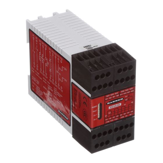
ES-UA-5A and ES-VA-5A E-Stop Safety
Modules
Model ES-UA-5A for 12-24V dc/115V ac operation; Model ES-
VA-5A for 12-24V dc/230V ac operation
Monitors emergency stop devices, such as palm buttons and rope/cable
pulls, and positive-opening safety switches used for guard/gate interlock-
ing
The safety inputs can monitor:
Hard/relay contacts in a dual-channel hookup using terminals S11-S12
and S21-S22, or
A +24V dc source switched by hard/relay contacts in single-channel
hookup
Four normally open output switching channels for connection to control-
reliable power interrupt circuits and three auxiliary output channels
Automatic reset or monitored manual reset
Design complies with standards ANSI B11.19, UL991, ISO 13850
(EN418), and ISO 13849-1 (EN954-1) (Safety Category 4)
For use in functional stop category 0 applications per ANSI NFPA 79
and IEC/EN60204-1
6 amp safety output contacts; 5 amp aux. output contacts
Plug-in terminal blocks
Outputs
12-24V dc
or
115V ac
4 Normally open safety
1 Normally closed aux.
2 Solid-state aux.
12-24V dc
or
230V ac
Output Rating
5/2010
N.O. Safety Outputs: 6 A
N.C. Aux. Outputs: 5 A
SS Aux. Outputs: 100 mA
0 122365 1
Advertisement
Table of Contents

Related Manuals for Banner ES-UA-5A


Summary of Contents for Banner ES-UA-5A
- Page 1 ES-UA-5A and ES-VA-5A E-Stop Safety Modules Model ES-UA-5A for 12-24V dc/115V ac operation; Model ES- VA-5A for 12-24V dc/230V ac operation Original Instructions Monitors emergency stop devices, such as palm buttons and rope/cable pulls, and positive-opening safety switches used for guard/gate interlock-...
-
Page 2: Applicable U.s. Standards
The user is responsible for satisfying all local, state, and national laws, rules, codes, and regulations relating to the use of this product and its application. Banner Engineering Corp. has made every effort to provide complete application, installation, operation, and maintenance instructions. Please direct any questions regarding the use or installation of this product to the factory applications department at the telephone numbers or address shown on back cover. - Page 3 As shown in the hookup S31 S32 S33 S34 S32 S35 drawings, the models ES-UA-5A and ES-VA-5A E-Stop Safety S11 S12 S21 S22 Modules (the Safety Modules) are designed to monitor a 1- channel or 2-channel E-stop switch. A 2-channel E-stop switch has two electrically isolated contacts.
- Page 4 Requirements vary widely for the level of control reliability or safety category per ISO 13849-1 (EN954-1) in safety applications. While Banner Engineering always recommends the highest level of safety in any application, it is the responsibility of the user to safely install, operate and maintain each safety system and comply with all relevant laws and regulations.
-
Page 5: Mechanical Installation
This classifies the Safety Module as a functional stop "Category 0" E-stop control, as defined by ANSI NFPA 79 and IEC/EN 60204-1. The Safety Module is powered by either a 12-24V dc supply at 4W or an ac supply (115V ac, model ES-UA-5A, or 230V ac, model ES-VA-5A) at 7VA. The safety inputs can be connected to: A +24V dc source that is switched by a hard/relay contact in single-channel hookup configuration, or Hard/relay contacts in a dual-channel hookup configuration using terminals S11-S12 and S21-S22. - Page 6 Periodically checking the functional integrity / safety function and training operators, maintenance personnel, and others associated with the operation of the machine to recognize and immediately correct such failures. If you have any questions about your intended use, please contact a Banner applications engineer at the numbers listed on the last page.
- Page 7 (e.g., through the use of rings or guards). If any areas are not visible from the reset switch(es), additional means of safeguarding must be provided. Failure to do so could result in serious bodily injury or death. P/N 122365 rev. C Banner Engineering Corp. - Minneapolis, MN USA - www.bannerengineering.com Tel: 763.544.3164...
- Page 8 Banner Engineering Corp. - Minneapolis, MN USA - www.bannerengineering.com P/N 122365 rev. C...
- Page 9 WARNING Outputs Power Supply Outputs Power Supply Energized Fault Energized Fault 12-24V dc 12-24V dc dc common dc common Figure 4: Hookup: 2-Channel E-stop applications P/N 122365 rev. C Banner Engineering Corp. - Minneapolis, MN USA - www.bannerengineering.com Tel: 763.544.3164...
- Page 10 WARNING Outputs Power Supply Outputs Power Supply Energized Fault Energized Fault 12-24V dc 12-24V dc dc common dc common Figure 5: Hookup: 1-Channel E-stop applications Banner Engineering Corp. - Minneapolis, MN USA - www.bannerengineering.com P/N 122365 rev. C Tel: 763.544.3164...
- Page 11 Whenever forced-guided, mechanically linked relays are added as intermediate switching devices, a normally closed forced-guided monitor contact from each relay must be added to the series feedback loop between Safety Module terminals S31 and S32. P/N 122365 rev. C Banner Engineering Corp. - Minneapolis, MN USA - www.bannerengineering.com Tel: 763.544.3164...
-
Page 12: Initial Checkout Procedure
3. If using manual reset mode, close and then open the reset switch within 2 seconds. Verify that the machine can be restarted by normal initiation. Banner Engineering Corp. - Minneapolis, MN USA - www.bannerengineering.com P/N 122365 rev. C Tel: 763.544.3164... -
Page 13: Specifications
Do not attempt any repairs to the Module. It contains no field-replaceable components. Return it to the fac- tory for warranty repair or replacement: Contact Banner Factory Application Engineering at the address or the numbers listed on the back page. They will attempt to troubleshoot the system from your description of the problem. - Page 14 Output at Y32 monitors state of outputs – conducts (output high) when both K1 and K2 are energized. Output at Y35 conducts (output high) when in normal operation (no lockout). Output Response Time 35 ms max. (25 ms typical) Banner Engineering Corp. - Minneapolis, MN USA - www.bannerengineering.com P/N 122365 rev. C Tel: 763.544.3164...
- Page 15 Max. Relative Humidity: 90% @ +50°C (non-condensing) Design Standards Cat. 4 PL e per EN ISO 13849-1; SIL 3 per IEC 61508 and IEC 62061 Certifications Emergency Stop Devices 29YL P/N 122365 rev. C Banner Engineering Corp. - Minneapolis, MN USA - www.bannerengineering.com Tel: 763.544.3164...
-
Page 16: Troubleshooting
Check connectors are properly seated. Ch2 LED ON No fault indicated Power LED ON Ch.1 closed; Ch. 2 open: Fault LED OFF Check wiring to S21-S22. Banner Engineering Corp. - Minneapolis, MN USA - www.bannerengineering.com P/N 122365 rev. C Tel: 763.544.3164... - Page 17 Check continuity of safety outputs (e.g. between termi- Ch1 LED ON nals 13 and 14). Ch2 LED ON Check control wires and connectors. Check MSCs. P/N 122365 rev. C Banner Engineering Corp. - Minneapolis, MN USA - www.bannerengineering.com Tel: 763.544.3164...
-
Page 18: Ec Declaration Of Conformity
ES-UA-5A and ES-VA-5A E-Stop Safety Modules EC Declaration of Conformity Banner Engineering Corp. herewith declares that ES-UA-5A and ES-VA-5A Emergency Stop Modules for industrial control are in conformity with the provisions of the Machinery Directive (Directive 2006/42/EC), and all essential Health and Safety Requirements have been met.
Need help?
Do you have a question about the ES-UA-5A and is the answer not in the manual?
Questions and answers