Banner EZ-SCREEN Instruction Manual
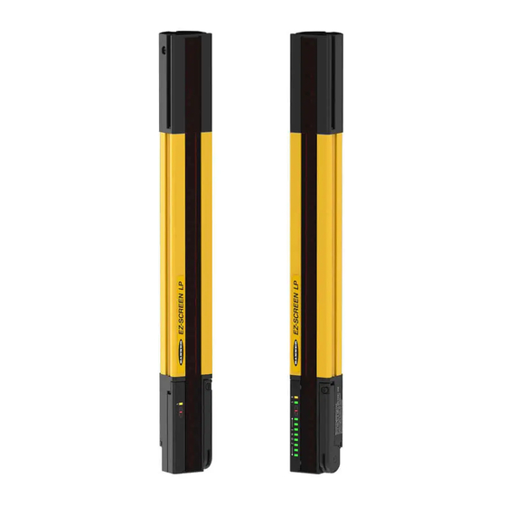
Lp limited function
safety light screen
Hide thumbs
Also See for EZ-SCREEN:
- Instruction manual (100 pages) ,
- Assembly (2 pages) ,
- Instruction manual (72 pages)

Subscribe to Our Youtube Channel
Related Manuals for Banner EZ-SCREEN


Summary of Contents for Banner EZ-SCREEN
- Page 1 ® EZ-SCREEN LP Limited Function Safety Light Screen Instruction Manual Original Instructions 197310 Rev. A 30 November 2016 © Banner Engineering Corp. All rights reserved 197310...
-
Page 2: Table Of Contents
6.3.2 Checking for Sources of Optical Noise ................42 6.4 Maintenance and Service ......................42 6.4.1 Cleaning ........................42 6.4.2 Replacement Parts ......................42 6.4.3 Banner Engineering Corp Limited Warranty ..............43 6.4.4 Warranty Service ......................43 6.4.5 Manufacturing Date .......................43... - Page 3 9.4 Muting Module ........................51 9.5 Safety Controllers ........................51 9.6 Snap-On Lens Shields ......................52 9.7 EZ-LIGHT ® for EZ-SCREEN ® ....................52 9.8 MSA Series Stands ......................... 53 9.9 MSM Series Corner Mirrors ...................... 53 9.10 SSM Series Corner Mirrors .....................
-
Page 4: About This Document
The precautions and statements used throughout this document are indicated by alert symbols and must be followed for the safe use of the EZ-SCREEN LP Limited Function Safety Light Screen. Failure to follow all precautions and alerts may result in unsafe use or operation. The following signal words and alert symbols are defined as follows:... -
Page 5: Introduction
EZ-SCREEN LP is extensively FMEA (Failure Mode and Effects Analysis) tested to establish an extremely high degree of confidence that, when appropriately installed, no system component will (even if it should fail) cause a failure to danger. -
Page 6: Components
2.2.1 Components An EZ-SCREEN LP “System” refers to a compatible emitter and receiver (equal length and resolution; available separately or in pairs), and cordset(s) for each. It also refers to the emitters and receivers in a cascade, and their cabling. Mounting hardware is included with each emitter and receiver;... -
Page 7: Appropriate Applications And Limitations
CAUTION: Install System Only on Appropriate Applications Banner EZ-SCREEN LP is for use only on machinery that can be stopped immediately after a stop signal is issued at any point in the machine's stroke or cycle, such as part-revolution clutched machines. -
Page 8: Examples: Inappropriate Applications
2.4 Control Reliability: Redundancy and Self-Checking Redundancy requires that EZ-SCREEN LP circuit components be backed up to the extent that, if the failure of a single component will prevent effective machine stopping action when needed, that component must have a redundant counterpart which will perform the same function. - Page 9 ® EZ-SCREEN LP Limited Function Safety Light Screen Emitter: Description Status Indicator (Red/Green)—Shows whether power is applied or the device is in a lockout condition. 7-segment Diagnostic Display—indicates specific error or configuration conditions. Figure 4. Emitter Receiver: 1-Digit Diagnostic Display—indicates specific error, configuration conditions, or total number of blocked beams.
-
Page 10: Mechanical Installation
The distance is calculated so that when an object or a person is detected (by blocking a sensing beam), the EZ-SCREEN LP sends a stop signal to the machine, causing it to stop by the time the object or person can reach any machine hazard point. - Page 11 (or the hazard removed). This can be broken down into two parts: Ts and Tr where T = Ts + Tr the maximum response time, in seconds, of the EZ-SCREEN LP emitter/receiver pair (depending on model) the additional distance, in mm, based on intrusion of a hand or object towards the danger zone prior to actuation of a safety device.
-
Page 12: Reducing Or Eliminating Pass-Through Hazards
S = (K × T ) + C Ds = K × ( Ts + Tr ) + Dpf Mount the EZ-SCREEN LP emitter and receiver so that no part of the defined area will be closer than 528 mm to the closest reachable hazard point on the guarded machine. -
Page 13: Supplemental Safeguarding
Figure 7. An example of supplemental safeguarding Figure 7 on page 13 shows an example of supplemental safeguarding inside a robotic work cell. The EZ-SCREEN LP, in conjunction with the hard (fixed) guarding, is the primary safeguard. Supplemental safeguarding (such as a horizontal- mounted safety light screen as an area guard) is required in areas that cannot be viewed from the reset switch (for example, behind the robot and the conveyor). - Page 14 Use of Corner Mirrors EZ-SCREEN LP may be used with one or more corner mirrors. Mirrors are not allowed for applications that would allow undetected personnel access into the safeguarded area. The use of glass-surface corner mirrors reduces the maximum specified emitter/receiver separation by approximately 8 percent per mirror, as follows: www.bannerengineering.com - Tel: 763.544.3164...
- Page 15 WARNING: Proper Orientation of System Emitters and Receivers EZ-SCREEN LP emitters and receivers must be installed with their corresponding cabled ends pointing in the same direction (for example, both cabled ends facing up). Failure to orient them properly will impair the performance of the EZ-SCREEN LP System and will result in incomplete guarding, and could result in serious bodily injury or death.
- Page 16 Figure 11. Examples of Incorrect Emitter/Receiver Orientation Installation of Multiple Systems Whenever two or more EZ-SCREEN LP emitter and receiver pairs are adjacent to one another, optical crosstalk may take place between the systems. To minimize optical crosstalk, alternate the positions of the emitters and receivers.
- Page 17 ® EZ-SCREEN LP Limited Function Safety Light Screen Receiver Receiver Emitter Emitter Emitter Emitter Receiver Receiver b. Two or three systems stacked (or alternate receiver/ a. Two systems in a horizontal plane emitter positions) Emitter Receiver 3 Emitter 3 Opaque Shield...
- Page 18 ® EZ-SCREEN LP Limited Function Safety Light Screen Mounting the End-Mount Brackets Figure 14. 360° Rotation • Two brackets are supplied with each emitter and receiver. • Brackets are designed to mount directly to MSA Series stands using the hardware supplied with the stands.
- Page 19 6. Tighten all fasteners. Bracket Assembly Instructions The screwdriver provided with the EZ-SCREEN LP is intended for access to the DIP switches and for preassembly of the mounting brackets. Final assembly (tightening) of the mounting bracket should be accomplished with a #1 Phillips screwdriver or 3/16 in.
- Page 20 ® EZ-SCREEN LP Limited Function Safety Light Screen Clamp Bracket Ensure that clamp assembly is fully seated onto “dovetail” feature on side of housing M3 x 6 Torque to 9 in-lbs (1.0 N-m) M3 x 10 Torque to 9 in-lbs (1.0 N-m)
- Page 21 ® EZ-SCREEN LP Limited Function Safety Light Screen Use the screwdriver provided with the EZ-SCREEN LP to access the DIP switches. Use a 3 mm hex driver to tighten the mounting bracket and achieve the listed torque specifications. ROTATION ADJUSTMENT Adjust clamp screw to loosen or tighten clamp.
- Page 22 ® EZ-SCREEN LP Limited Function Safety Light Screen Sensor Mounting and Mechanical Alignment Verify that: • The emitter and receiver are directly opposite each other • Nothing is interrupting the defined area • The defined area is the same distance from a common reference plane for each sensor •...
- Page 23 ® EZ-SCREEN LP Limited Function Safety Light Screen Mounting Dimensions and Defined Area All measurements are listed in millimeters [inches], unless noted otherwise. 33.0 [1.30"] 20.0 [0.79"] 10.0 [0.39"] 26.0 [1.02"] 28.0 [1.10"] 9.4 [0.37"] R 13mm [0.5"] min. bend...
- Page 24 ® EZ-SCREEN LP Limited Function Safety Light Screen End-Cap Brackets LPA-MBK-11 32.0 [1.26"] 16.0 [0.63"] 32.9 [1.30"] 2x 10.0 [0.39"] 3x 5.5 [0.22"] 10.0 [0.39"] 11.9 [0.47"] 39.8 [1.57"] 19.0 [0.75"] Side-Mount Bracket LPA-MBK-12 38.9 [1.53"] 6.0 [0.23"] 20.0 [0.79"] 32.5 [1.28"]...
- Page 25 ® EZ-SCREEN LP Limited Function Safety Light Screen Side-Mount Bracket LPA-MBK-16 Figure 22. Optional mounting bracket—dimensions (for emitter or receiver) www.bannerengineering.com - Tel: 763.544.3164...
-
Page 26: Electrical Installation And Testing
Emitter and receiver wiring is low voltage; routing the sensor wires alongside power wires, motor/servo wires, or other high voltage wiring may inject noise into the EZ-SCREEN LP System. It is good wiring practice, and sometimes may be required by code, to isolate emitter and receiver cables from high-voltage wires, avoid routing cables close to “noisy”... -
Page 27: Initial Electrical Connections
All connections are made through the RD or pigtail QD connections. Emitter Cordset EZ-SCREEN LP emitters have an 8-pin cordset, but not all conductors are used. The other wires are in place to allow a parallel connection (color-for-color) to the receiver cable, providing sensor interchangeability (or “swapability”);... -
Page 28: Optical Alignment
Reference Wiring Diagrams on page 35). 6. Power up the EZ-SCREEN LP System only. 7. Verify that the input power is present to both the emitter and the receiver. At least one indicator on both the emitter and the receiver should be On and the start-up sequence should cycle. -
Page 29: Optical Alignment Procedure With Mirrors
4.3.4 Optical Alignment Procedure with Mirrors EZ-SCREEN LP sensors may be used with one or more corner mirrors for guarding more than one side of an area. The MSM-... and SSM-... rear-surface glass mirrors are rated at 85% efficiency. Thus, excess gain and sensing range are reduced when using mirrors;... -
Page 30: Trip Test
After optimizing the optical alignment and configuring fixed blanking and/or reduced resolution (if applicable), perform the trip test to verify the detection capability of the EZ-SCREEN LP System. This test also verifies correct sensor orientation, identifies optical short circuits, and verifies the expected resolution for applications using reduced resolution. After the installation has passed the trip test, the safety outputs may be connected and the commissioning checkout may be performed (initial installations only). -
Page 31: Electrical Connections To The Guarded Machine
WARNING: If Trip Test Indicates a Problem If the EZ-SCREEN LP System does not respond properly to the trip test, do not attempt to use the System. If this occurs, the System cannot be relied on to stop dangerous machine motion when a person or object enters the defined area. -
Page 32: Fsd Interfacing Connections
Depending on the application, the use of FSDs can facilitate controlling voltage and current that differs from the OSSD outputs of the EZ-SCREEN LP. FSDs can also be used to control an additional number of hazards by creating multiple safety stop circuits. -
Page 33: Machine Primary Control Elements
EZ-SCREEN LP is ready for testing in combination with the guarded machine. The operation of the EZ-SCREEN LP with the guarded machine must be verified before the combined System and machine may be put into service. To do this, a Qualified Person must perform the Commissioning Checkout Procedure. -
Page 34: Commissioning Checkout
To prepare the System for this checkout: 1. Examine the guarded machine to verify that it is of a type and design compatible with the EZ-SCREEN LP System. See Examples: Inappropriate Applications on page 8 for a list of misapplications. -
Page 35: Reference Wiring Diagrams
16. Remove electrical power to the EZ-SCREEN LP. Both OSSD outputs should immediately turn Off, and the machine must not be capable of starting until power is re-applied to the EZ-SCREEN LP. -
Page 36: Generic Emitter Wiring Diagram
® EZ-SCREEN LP Limited Function Safety Light Screen 4.5.1 Generic Emitter Wiring Diagram +24 V dc 0 V dc 8-pin male Euro-style Bn (Pin #1) face view Gn/Ye (#7) Bu (#6) Bk (#5) n.c.* Wh (#4) n.c.* Vi (#8) n.c.* Or (#3) n.c.*... -
Page 37: System Operation
EZ-SCREEN LP System and its integration with the guarded machine. In addition to everything for which the Designated Person is empowered, the Qualified Person is empowered to: •... -
Page 38: Normal Operation
No manual reset operation is required. 5.3.2 Run Mode If any beams become blocked while the EZ-SCREEN LP is running, the receiver outputs turn Off within the stated EZ- SCREEN LP response time (see GUID-92E22EE9-735B-4C44-8FFC-2C2184930F37). If all the beams then become clear, the receiver outputs come back On. -
Page 39: Troubleshooting And Maintenance
6.1 Lockout Conditions A Lockout condition causes all of the EZ-SCREEN LP OSSD outputs to turn or remain Off, sending a stop signal to the guarded machine. Each sensor provides diagnostic error codes to assist in the identification of the cause(s) of lockouts (see Receiver Error Codes and Emitter Error Codes) or the Diagnostic Error Code label supplied in the documentation pack). -
Page 40: Receiver Error Codes
• Verify that the reset switch is in the open position. • Reset the receiver per EZ-SCREEN Checkout Procedures: Shift and This error occurs when the Reset switch is closed Daily Checkout Procedure. (or the wiring is shorted to +24 V) during power- •... -
Page 41: Electrical And Optical Noise
6.3 Electrical and Optical Noise The EZ-SCREEN LP is designed and manufactured to be highly resistant to electrical and optical noise and to operate reliably in industrial settings. However, serious electrical and/or optical noise may cause a random Trip condition. In extreme electrical noise cases, a Lockout is possible. -
Page 42: Checking For Sources Of Electrical Noise
2. Cover the lens of the BT-1 with electrical tape to block optical light from entering the receiver lens. 3. Press the RCV button on the BT-1 and position the Beam Tracker on the wires going to the EZ-SCREEN LP or any other nearby wires. -
Page 43: Banner Engineering Corp Limited Warranty
Important: If instructed to return the device, pack it with care. Damage that occurs in return shipping is not covered by warranty. 6.4.5 Manufacturing Date Every EZ-SCREEN LP produced is marked with a code that defines the week and year of manufacture and manufacturing location. The code format (U.S. Standard format) is: YYWWL •... -
Page 44: Checkout Procedures
A copy of the checkout results should be recorded Qualified Person Checkout (either a new configuration of the EZ-SCREEN LP and kept in the appropriate place (for example, or changes to the machine). near or on the machine, in the machine's technical file). -
Page 45: Specifications
Only standard yellow housing models are listed. Pigtail QD models (for example, SLPE14-270P8) have yellow PVC cable and black PVC QD overmold. For other models, see below. www.bannerengineering.com or call Banner Engineering for kit model numbering scheme. Order one machine interface cordset for each emitter or receiver; see Cordsets on page 48. -
Page 46: General Specifications
Cordsets on page 48 for recommended cables. If other cables Operating Conditions are used with the EZ-SCREEN LP, the user must verify suitability of Temperature: 0 °C to +55 °C (+32 °F to +131 °F) these cables for each application. -
Page 47: Receiver Specifications
® EZ-SCREEN LP Limited Function Safety Light Screen 8.5 Receiver Specifications Supply Voltage at the Device Output Signal Switching Devices (OSSDs) 24 V dc ±15% (use a SELV-rated power supply according to EN IEC Two redundant solid-state 24 V dc, 0.5 A max. sourcing OSSD 60950). -
Page 48: Accessories
® EZ-SCREEN LP Limited Function Safety Light Screen 9 Accessories Additional interfacing solutions and accessories continue to be added; refer to http://www.bannerengineering.com for a current list. 9.1 Cordsets Machine interface cordsets provide power to the first emitter/receiver pair. Sensor interconnect cables provide power to subsequent emitters and receivers in the cascade. -
Page 49: Splitter Cordsets
9.1.4 Splitter Cordsets Used for easy interconnection between an EZ-SCREEN LP receiver and its emitter, providing a single “homerun” cable. Model DEE2R-.. double-ended cordsets may be used to extend the QD trunk or either branch. (Branch #1 and branch #2 cable sections are 300 mm/1 ft long.) Model QDE-8..D single-ended cordsets may be used to extend the QD trunk for cut-... -
Page 50: Male M12/Euro To Female M12/Euro Qd Cordsets
® EZ-SCREEN LP Limited Function Safety Light Screen Pin #1 (+24V dc) Pin #1 (+24V dc) Pin #2 (n.c.) Pin #2 (n.c.) Pin #3 (n.c.) Pin #3 (n.c.) Pin #4 (OSSD#2) Pin #4 (OSSD#2) Pin #5 (OSSD#1) Pin #5 (OSSD#1) -
Page 51: Bulkhead Connector
18 amp positive-guided contactor, 3 N.O., 1 N.C. (N.C. contact rated at 10 amps) 9.4 Muting Module Provides the muting capability for the EZ-SCREEN LP. See Banner manuals p/n 63517 or 116390 for more information and additional cabling options. Model... -
Page 52: Snap-On Lens Shields
® ® 9.7 EZ-LIGHT for EZ-SCREEN Provides clear, 360° indication of the of the EZ-SCREEN receiver's output status. Use with a CSB splitter cable and optional DEE2R double-ended cables. See data sheet p/n 121901 for more information. Models Construction Connector/LED Function/Inputs Nickel-plated brass housing, M18x1 thread;... -
Page 53: Msa Series Stands
® EZ-SCREEN LP Limited Function Safety Light Screen Models Construction Connector/LED Function/Inputs Polycarbonate housing, 50 mm thermoplastic dome, 30 mm base mount K50LRGX8PQ8 Fully encapsulated, IP67 Polycarbonate housing, 50 mm thermoplastic dome, flat or DIN mount K80LRGX8PQ8 Encapsulated electronics, IP67 9.8 MSA Series Stands... -
Page 54: Ssm Series Corner Mirrors
1800 mm (70.9 in) 1900 mm (74.8 in) 2011 mm (79.2 in) 1978 mm (77.9 in) 9.11 Accessory Mounting Brackets Contact Banner Engineering for more information. Order one LPA-MBK-.. bracket per sensor, two per pair. Model Description • Adaptor for side-mount bracket LPA-MBK-12 •... - Page 55 • Universal adapter bracket for mounting to engineered/slotted ™ aluminum framing (for example, 80/20 , Bosch) • Retrofit for Banner MS/US/MG; clearance for M4 and M6 hardware LPA-MBK-20 • Use with LPA-MBK-11, -12, or -13 • 12 ga (2.66 mm) steel, black zinc plated •...
-
Page 56: Alignment Aids
BRT-THG-2-100 2 inch retroreflective tape, 100 ft BT-1 Beam Tracker 9.13 Literature The following documentation is supplied with each EZ-SCREEN LP receiver. Additional copies are available at no charge; contact Banner Engineering or visit www.bannerengineering.com. Part Number Description 197310 EZ-SCREEN LP Limited Function Safety Light Screen Instruction Manual 140045 Checkout Procedure Card (Daily)—Stand-Alone Systems... - Page 57 ® EZ-SCREEN LP Limited Function Safety Light Screen Part Number Description 140046 Checkout Procedure Card (Daily)—Cascaded Systems 140047 Checkout Procedure Card (Semi-Annual) 147360 EZ-SCREEN LP Bracket Supplement www.bannerengineering.com - Tel: 763.544.3164...
-
Page 58: Standards And Regulations
10 Standards and Regulations The list of standards below is included as a convenience for users of this Banner device. Inclusion of the standards below does not imply that the device complies specifically with any standard, other than those specified in the Specifications section of this manual. - Page 59 Email: salesindia@bannerengineering.com Pune 411016, India Mexico Address: Phone: +52 81 8363 2714 or 01 800 BANNERE (toll free) Banner Engineering de Mexico Monterrey Head Office Website: www.bannerengineering.com.mx Edificio VAO Av. David Alfaro Siqueiros No.103 Col. Valle Oriente C.P.66269 Email: mexico@bannerengineering.com...
-
Page 60: Glossary
® EZ-SCREEN LP Limited Function Safety Light Screen 11 Glossary ANSI (American National Standards Institute) Auto Power-Up Acronym for the American National Standards A safety light screen system feature that enables the Institute, an association of industry representatives system to be powered up into Run mode (or recover... - Page 61 Lockout condition machine primary control element (MPCE) when the are permitted; failures which cause an unsafe output signal switching device (OSSD) goes to the condition (a failure to danger) are not. Banner safety OFF-state. products are extensively FMEA tested. Fixed Blanking...
- Page 62 ® EZ-SCREEN LP Limited Function Safety Light Screen Internal Lockout A Lockout condition that is due to an internal safety system problem. Generally, indicated by the red Status indicator LED (only) flashing. Requires the attention of a Qualified Person. Key Reset (Manual Reset)
- Page 63 (after the operation) by the operator. PSDI is commonly confused with "Trip Initiate." PSDI is defined in OSHA CFR1910.217. Banner safety light screen systems may not be used as PSDI devices on mechanical power presses, per OSHA regulation 29 CFR 1910.217.
- Page 64 When inserted into any part of the properly. Banner safety light screen systems and defined area, it will place a system into a Trip or safety modules are self-checking.
- Page 65 Index receiver 37 light-emitting diodes 37 initial power-up 27 LEDs See also LEDs emitter 37...
Need help?
Do you have a question about the EZ-SCREEN and is the answer not in the manual?
Questions and answers