
Related Manuals for Oneida Air Systems XCKM013000


Summary of Contents for Oneida Air Systems XCKM013000
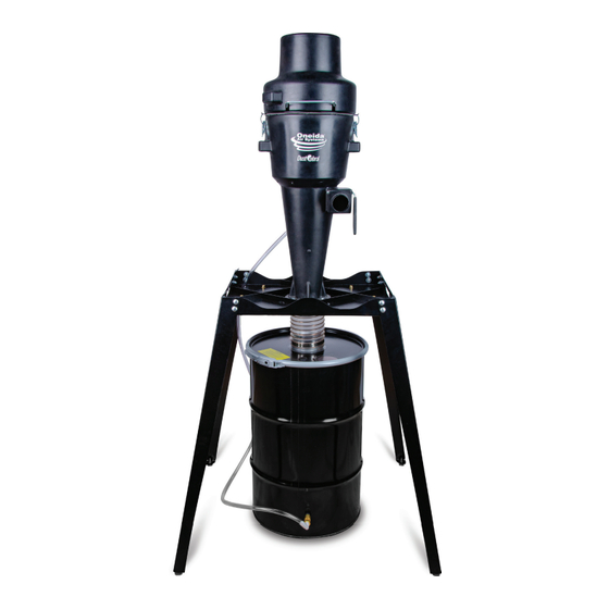
- Page 1 Owner’s Manual Dust Cobra Dust Collector Industrial 30/35 Gallon Freestanding #XCKM013000 #XCKM013511 Patents: www.oneida-air.com/patents Appearance may vary slightly Doc. #ZBM000064 Rev: A 20230614LL...
-
Page 3: Table Of Contents
Table of Contents System Start-Up Information System Specifications System Dimensions System with Dolly and Stand Dimensions System Contents Assembly Instructions Maintenance Troubleshooting Warranty Information Recommended Accessories Recommended Accessories Notes oneida-air.com... -
Page 4: System Start-Up Information
Consult this owner’s manual or reach out for recommended accessories. 13. ENSURE enough air volume is at the suction point to capture all the particulate generated. Oneida Air Systems, Inc. - Page 5 Information (Continued) 14. NEVER make modifications without prior approval from Oneida Air Systems. Modifying the dust collector or using it differently than intended will void the warranty and may result in malfunction or mechanical failure that leads to serious personal injury or death! 15.
- Page 6 Oneida Air Systems assumes no responsibility or liability for the suitability of any fire and/ or explosion mitigation strategy, or any items incorporated into a collector as part of an owner/operators hazard mitigation strategy.
- Page 7 system start-up Information (Continued) 12. ALWAYS check your dust bin for smoldering materials before leaving the shop. 13. NEVER introduce sparks or sources of ignition into the dust collector. Sparks can be generated in several ways: a. High speed sanders, abrasive planers, saws, and edgers may strike foreign material and create a red-hot metal fragment.
-
Page 8: System Specifications
Cyclone Body Industrial, Static Conductive Resin Inlet Size 2.5" O.D. (2.25" I.D.) Inlet Dimensions 2.3" ID Drum Type Reinforced Steel Drum with Painted Exterior Container Size 30 Gallons/35 gallons Overall Height 30 Gallon: 53.5" / 35 Gallon: 59.25" Oneida Air Systems... - Page 9 System Specifications Keep the Certificate of Compliance on hand while doing lead remediation WARNINg This motor can expose you to chemicals, including carbon black, which is known to the State of California to cause cancer. For more information go to www.P65Warnings.ca.gov oneida-air.com...
-
Page 10: System Dimensions
Dimensions Nominal dimensions shown. Dimensions subject to slight variations in manufacturing. 34-1/2" 875 mm 39-1/2" 1,002 mm 54-3/16" 1,376 mm 52-3/16" 1,326 mm 30 Gallon: 29-9/16" 751 mm 35 Gallon: 22-1/4" 565 mm Oneida Air Systems... -
Page 11: System With Dolly And Stand Dimensions
system with Dolly and stand Dimensions Nominal dimensions shown. Dimensions subject to slight variations in manufacturing. 43-1/2" 1,105 mm 39-1/2" 1,004 mm Floor 58-1/8" 1,476 mm 56-1/8" 1,426 mm oneida-air.com... -
Page 12: System Contents
Quick Disconnect Kit F25A RLH000006 1/4" NPT Nylon Elbow Please unpack the parts carefully and confirm you have received each item listed here. * Some components are pre-installed at the factory and are listed here for your convenience. 10 Oneida Air Systems... - Page 13 system Contents (Continued) Filter Attachment Hardware Motor Attachment Hardware Hose Storage Hardware × 16 × 16 Mounting Hardware × 8 × 16 × 8 × 8 F26A F26B F26C Vent Tube Quick Disconnect Pack F25A F25B F25C F25D F25E F25F oneida-air.com...
-
Page 14: Assembly Instructions
(D) so that it is fully covering the top edge [FIG. 1a]. The Handle Gasket should be nested within the divots on each side of the Handle [FIG. 1b]. Repeat for both Handles. FIG. 1a Divots FIG. 1b Oneida Air Systems, Inc. - Page 15 assembly Instructions (Continued) Install a Mounting Foot (F4) into the threaded insert located on the bottom of each Stand Leg (E) [FIG. 2]. Note: Firmly hand-tighten but do not over torque as this may damage the connection point. FIG. 2 Locate the lower grouping of four mounting holes on each of the Stand Legs (E).
- Page 16 Thumb Nut (F10) [FIG. 5a]. Insert a Push-in Plug (F12) into the two remaining holes [FIG. 5b]. FIG. 5a FIG. 5b Note: Silicone (F13) can be applied to the Push- In Plugs for a more permanent installation. Oneida Air Systems, Inc.
- Page 17 assembly Instructions (Continued) Align the Cone Assembly (B), right side up and align the Cobra Gasket (F27), the bottom flange of the Cone Assembly (B), and the Stand Body (D) [FIG. 6]. FIG. 6 Secure the Cone Assembly (B) to the Stand Body (D) with eight Hex Head Bolts (F29), sixteen Flat Washers (F30), and eight Whiz- Lock Nuts (F31) as shown in [FIG.7].
- Page 18 Note: Which hole you use will be determined Either Hole by the orientation of your Cone Assembly (B). Use whichever hole is closest to ensure adequate length for the Tubing Assembly to connect to the Drum (I). FIG. 10 16 Oneida Air Systems...
- Page 19 assembly Instructions (Continued) Install the Quick-Disconnect Kit (F25) onto F25A F25B F25D F25F the pre-drilled hole near the bottom section of the Drum (I) [FIG. 11a]. Refer to the Quick Disconnect Installation Sheet for more information. Note: If you are not using the automatic bag F25C F25E holding feature of the system, the Valve of...
- Page 20 [FIG. 14]. Note: The Drum should be rotated so that the inlet is closest to the wall to provide the best visibility to the fill viewing window on the Drum Lid. FIG. 14 18 Oneida Air Systems...
- Page 21 assembly Instructions (Continued) Install the Dust Sentry Infrared Sensor (J) to Infrared Sensor the Drum Lid's (H) pre-cut hole [FIG. 15] Hole • Refer to the Dust Sentry Installation Sheet Window for more information. Mini-G Window Note: If you are not using the Dust Sentry infrared Dust Sentry Discharge ensure that the infrared sensor hole is sealed...
- Page 22 1-11/16". [FIG. 19b] Install Filter Retainer Strap (F21) onto the J Bolts [FIG. 19c] Note: If your filter retainer strap has steel S-hooks on the ends, remove and discard. They are not needed for the install. FIG. 19c 20 Oneida Air Systems...
- Page 23 assembly Instructions (Continued) Carefully install the GORE® CleanStream Pro HEPA Filter (C) onto the ring and then slip filter retainer strap (F21) to secure. [FIG. 20] Note: It is VERY important that the strap be tight enough to hold the filter snugly in place yet not so tight as to pull down and damage the filter.
- Page 24 Clamp (F32) [FIG. 24a]. Cleanshop Accessories (K2) and the 4 to 2-1/2" Reducer (K3) are friction fit to collec from your tools and to aid with all your cleanup jobs [FIG. 24b]. Installation is complete! FIG. 24a FIG. 24b 22 Oneida Air Systems...
-
Page 25: Maintenance
Maintenance Do NOT shut off air to inlet for extended periods of time. This can cause motor to overheat and shut off! Filter pulse bar Cleaning Cleaning the Filter Internal Rapid Pulse Filter Cleaner™ System helps to Proper filter cleaning should not be neglected as a keep the flow continuous and remove the clogging of dirty filter can significantly affect your dust collector’s the filter. - Page 26 4. Replacement bags should be 14 x 16 x 36" and at least 1.5 mils thick. See Accessories page for replacement bags needed for your system. When you are not using a bag in your drum then you must close the Switch Valve (G31B). 24 Oneida Air Systems...
-
Page 27: Troubleshooting
Troubleshooting pROblEM C AUSE SOlUTION Bag sucked up into the Air leaks in the drum 1. Confirm the lid of the dust drum is be in place and be well seated when operating. cyclone 2. Check for any damage on the foam seal of the lid. 3. -
Page 28: Warranty Information
In no event shall Oneida Air Systems’ liability under this warranty exceed the purchase price paid for the product and any legal actions brought against Oneida Air Systems shall be tried in the State of New York, County of Onondaga. -
Page 29: Recommended Accessories
recommended accessories gORE CleanStream® pRO HEpA Filter (Dome Top) for Dust Cobra #FCH000004 • Certified HEPA Filter Media. • Wide-spaced pleated filters with non-stick coating for quick and easy dust removal. • Perfect for drywall or any other type of dust. Replacement Dust Cobra Motor brushes #BRB001205 • Package of replacement motor brushes for the Dust Cobra HEPA Vacuum system. -
Page 30: Recommended Accessories
2.5" x 25' Contractor Multi-Tool Hose package #AHX000012 • Includes three 2.5” x 12.5’ lightweight, reinforced vacuum hoses, five turn-key hose clamps, and a 45 degree y-branch. • Effectively connect two tools to your dust extract or with minimal loss of airflow. 28 Oneida Air Systems... -
Page 31: Notes
notes oneida-air.com... - Page 32 Regardless of where you purchased your system, if you have any questions or issues with missing / damaged parts, please call Oneida Air Systems first to let us help resolve your problem. We fully stand behind the quality of our products and place the utmost value on the satisfaction of our customers.
Need help?
Do you have a question about the XCKM013000 and is the answer not in the manual?
Questions and answers