Bender ISOMETER isoCHA425HV Manual
Hide thumbs
Also See for ISOMETER isoCHA425HV:
- Manual (46 pages) ,
- User manual (13 pages) ,
- Quick start manual (13 pages)
Table of Contents
Advertisement
Quick Links
Advertisement
Table of Contents

Related Manuals for Bender ISOMETER isoCHA425HV


Summary of Contents for Bender ISOMETER isoCHA425HV
- Page 1 Manual EN ISOMETER® isoCHA425HV Insulation monitoring device with coupling device AGH420-1/AGH421-1 For unearthed DC systems 0 V to 1000 V Suitable for DC charging stations according to CCS or CHAdeMO Software version: D0624 V4.xx isoCHA425HV_D00404_04_M_XXEN/10.2023...
- Page 2 isoCHA425HV_D00404_04_M_XXEN/10.2023...
-
Page 3: Table Of Contents
Indication of important instructions and information...............6 Signs and symbols............................6 Service and Support............................6 Training courses and seminars........................7 Delivery conditions............................7 Inspection, transport and storage......................7 Warranty and liability.............................7 Disposal of Bender devices..........................8 1.10 Safety..................................8 Function.......................9 Intended use..............................9 Device features..............................9 Functional description..........................10 2.3.1... - Page 4 Table of contents Dimensions..............................18 Installation................................18 Connection...............................18 Commissioning...............................21 Operation......................22 Operating and display elements......................22 Menu overview...............................24 Displaying measured values........................25 Setting the response values (AL)......................26 4.4.1 Response values overview.........................26 4.4.2 Setting the response values for monitoring the insulation resistance........26 4.4.3 Setting the response values for undervoltage and overvoltage..........26 Configuring fault memory, alarm relays, and interfaces (out)............26...
- Page 5 ISOMETER® isoCHA425HV Standards and certifications........................49 Ordering data..............................50 Document revision history........................50 isoCHA425HV_D00404_04_M_XXEN/10.2023...
-
Page 6: General Information
Protect from dust Temperature range Recycling RoHS directives Service and Support Information and contact details about customer service, repair service or field service for Bender devices are available on the following website: Fast assistance | Bender GmbH & Co. KG. isoCHA425HV_D00404_04_M_XXEN/10.2023... -
Page 7: Training Courses And Seminars
Regular face-to-face or online seminars for customers and other interested parties: www.bender.de > know-how > seminars. Delivery conditions The conditions of sale and delivery set out by Bender GmbH & Co. KG apply. These can be obtained in printed or electronic format. The following applies to software products: ‘Software clause in respect of the licensing of standard software as part of deliveries,... -
Page 8: Disposal Of Bender Devices
General information Disposal of Bender devices Abide by the national regulations and laws governing the disposal of this device. For more information on the disposal of Bender devices, refer to www.bender.de > service & support. 1.10 Safety If the device is used outside the Federal Republic of Germany, the applicable local standards and regulations must be complied with. -
Page 9: Function
ISOMETER® isoCHA425HV Function Intended use The ISOMETER® isoCHA425HV in combination with the AGH420-1/AGH421-1 coupling device monitors the insulation resistance R for DC fast charging stations according to the CHAdeMO standard or according to the Combined Charging System (CCS) for nominal system voltage ranges between DC 0 V and 1000 V. In order to meet the requirements of the applicable standards, customised parameter settings must be made on the equipment in order to adapt it to local equipment and operating conditions. -
Page 10: Functional Description
Function • Activatable fault memory • RS-485 (galvanically isolated) including the following protocols: – BMS (Bender measuring device interface) for the data exchange with other Bender devices – Modbus RTU – IsoData (for continuous data output) • Password protection against unauthorised changing of parameters •... -
Page 11: R F And C E In "Chd" And "Cha" Mode (Chademo)
ISOMETER® isoCHA425HV 2.3.1 and C in “CHd” and “CHA” mode (CHAdeMO) The insulation fault R and the system leakage capacitance C are only determined for DC system voltages ≥ 50 V. The maximum permissible system leakage capacitance C is 1.6 F per conductor. In mode “CHd” the value R is determined by the smaller of the values R and R... -
Page 12: Functional Tests Of Contactors In The Charging Station And The Vehicle
Function 2.3.6 Functional tests of contactors in the charging station and the vehicle If the ISOMETER® is disconnected on one pole from the monitored voltage source during a functional test of the charging station or vehicle contactors, a false alarm may occur depending on the location of an existing insulation fault. - Page 13 ISOMETER® isoCHA425HV 2.3.10.1 Cyclic background test The cyclic background test checks the functionality of the C. It is not visible to the user and does not influence the measuring function. In case of malfunction, the respective device error messages “E.09” to “E.16” appear. 2.3.10.2 Continuous PE connection monitoring The connection of terminal “E”...
-
Page 14: 2.3.11 Error Codes
Function 2.3.11 Error codes In the event of a device error the display shows the respective error code. Overview of some error codes Error code Meaning PE connection error The connection of “E” or “KE” to earth is interrupted. E.01 Action: Check connection, eliminate error. -
Page 15: 2.3.13 Fault Memory
The ISOMETER® uses the serial hardware interface RS-485 with the following protocols: • BMS The BMS protocol is an essential component of the Bender measuring device interface (BMS bus protocol). Data transmission generally makes use of ASCII characters. • Modbus RTU Modbus RTU is an application layer messaging protocol, and it provides master/slave communication between devices that are connected via bus systems and networks. -
Page 16: 2.3.15 Measuring And Response Times
Function 2.3.15 Measuring and response times The measuring time is the period essential for the detection of the measured value. The measuring time is reflected in the operating time t . For the insulation resistance measured value, it is mainly determined by the necessary measuring pulse duration, which depends on the insulation resistance R and the system leakage capacitance C... -
Page 17: 2.3.18 History Memory His
ISOMETER® isoCHA425HV When the measuring function is stopped, the display shows “StP”. Stop mode can also be triggered via an interface command, and in this case it can only be reset via the interface. If coupled with AGH421-1, the activation of stop mode via the interface command disconnects the ISOMETER® from the monitored network. -
Page 18: Installation, Connection And Commissioning
Installation, connection and commissioning Installation, connection and commissioning Dimensions 45 70.5 31.1 47.5 74.5 Figure: Dimension diagram (in mm) Installation CAUTION Property damage due to heat When operating on system voltages U > 800 V, the housing of the AGH can become hotter than 60 °C. •... - Page 19 ISOMETER® isoCHA425HV For details about the required conductor cross sections, refer to chapter “Technical data”, page 42. Wiring diagram legend: Terminal Connections Connection to the supply voltage U via fuse: A1, A2 If supplied from an IT system, both lines have to be protected by a fuse.* Connect each terminal separately to PE: E, E, KE Use the same wire cross section as for “A1”, “A2”.
- Page 20 Installation, connection and commissioning Wiring diagram Figure: Wiring diagram isoCHA425HV_D00404_04_M_XXEN/10.2023...
-
Page 21: Commissioning
ISOMETER® isoCHA425HV Commissioning Check that the ISOMETER® is properly connected to the system to be monitored. Connect supply voltage U to the ISOMETER®. The start routine can take up to 30 s. Afterwards, the current insulation resistance is shown as the standard display. -
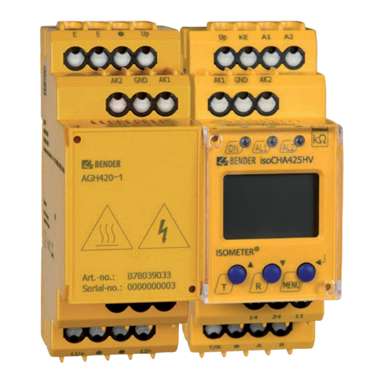
Page 22: Operation
Operation Operation Operating and display elements Device front Operating elements Function Power LED AL1 AL2 Alarm LEDs (For codes see “Assigning the alarm messages to the relays”, page 27.) Up and down buttons – For navigating up or down in the menu settings. - Page 23 ISOMETER® isoCHA425HV Display Display elements Function System voltage U Insulation resistance R System leakage capacitance C Monitored conductors L1 L2 Voltage type DC Pulse symbol: error-free measured value update Voltage type AC °C Measured values and units μ n F Hz k M Ω...
-
Page 24: Menu Overview
Operation Menu overview Measurement display Menu selection Parameter selection Menu item Parameter Querying and setting response values Configuring fault memory, alarm relays and interface Setting delay times and self test cycles Setting device control parameters Querying software version Querying and clearing the history memory Going to the next-higher menu level isoCHA425HV_D00404_04_M_XXEN/10.2023... -
Page 25: Displaying Measured Values
ISOMETER® isoCHA425HV Displaying measured values Overview Display Description Insulation resistance R 1 k … 2 M ✓ ± R k The “+” or “–” sign appears, when an error of R < 500 k is mainly detected at L1/+ or L2/– with |R%| ≥ 30 %. System voltage U (L1/+ - L2/–) …... -
Page 26: Setting The Response Values (Al)
Operation Setting the response values (AL) 4.4.1 Response values overview Display Activation Setting value Description Range Prewarning value R R1 < R2 … 600 Hys. = 25 % / min. 1 k Alarm value R R2 < 5 … R1 Hys. -
Page 27: Configuring The Relays
ISOMETER® isoCHA425HV 4.5.1 Configuring the relays Relay K1 Relay K2 Description Display Display Relay operating mode n/c or n/o FAC Factory settings Customer settings 4.5.2 Assigning the alarm messages to the relays The “on” setting assigns an alarm message to the respective relay. The LED indication is directly assigned to the alarm message and is not related to the relays. -
Page 28: Activating Or Deactivating Fault Memory
Operation 4.5.3 Activating or deactivating fault memory Display Description Memory function for alarm messages (fault memory) FAC Factory settings Customer settings 4.5.4 Configuring interface Display Setting value Description Range Adr = 0 deactivates BMS as well as Modbus 0 / 3…90 Bus Adr. -
Page 29: Setting Device Control Parameters (Set)
> DC 100 V S.Ct Device test at device start Restore factory settings For Bender Service only FAC Factory settings Customer settings Reset to factory settings All settings with the exception of the interface parameters are reset to the factory settings. -
Page 30: Querying Software Version (Inf)
Operation Show history memory Call up “HiS” menu and go up or down. Delete history memory Call up “HiS” menu, go to “Clr” and confirm. 4.10 Querying software version (InF) The software version is displayed as a ticker. Afterwards it can be output step by step using the up or down buttons. -
Page 31: Data Access Via Rs-485 Interface
ISOMETER® isoCHA425HV Data access via RS-485 interface Data access using the BMS protocol The BMS protocol is an essential component of the Bender measuring device interface (BMS bus protocol). Data transmission generally makes use of ASCII characters. BMS channel no. -
Page 32: Writing The Modbus Register (Parameter Setting)
Data access via RS-485 interface Command of the master to the ISOMETER® In the following example, the master of the ISOMETER® requests the content of register 1003 using address 3. The register contains the channel description of measuring channel 1. Byte Name Example... -
Page 33: Exception Code
ISOMETER® isoCHA425HV Response of the ISOMETER® to the master Byte Name Example Byte 0 ISOMETER® Modbus address 0x03 Byte 1 Function code 0x10 Byte 2, 3 Start register 0x0BBB Byte 4, 5 Number of registers 0x0001 Byte 6, 7 CRC16 checksum 0x722A 5.2.3 Exception code... -
Page 34: Modbus Register Assignment
Data access via RS-485 interface Modbus register assignment 5.3.1 Modbus measured value registers Depending on the device condition, the information in the registers is the measured value without alarm, the measured value with alarm 1, the measured value with alarm 2, or the device error. For more information see , page 35. - Page 35 ISOMETER® isoCHA425HV 5.3.1.2 Float = Floating point value of the channels Representation of the bit order for processing analogue measured values according to IEEE 754 Word 0x00 0x01 Byte HiByte LoByte HiByte LoByte 31 30 29 28 27 26 25 24 23 22 21 20 19 18 17 16 15 14 13 12 11 10 exponent mantissa sign...
- Page 36 Data access via RS-485 interface 5.3.1.4 R&U = Range and unit Meaning Unit Invalid (init) No unit Baud °C °F Second Minute Hour Month Range of validity Actual value The actual value is lower The actual value is higher Invalid value •...
-
Page 37: Modbus Parameter Register
ISOMETER® isoCHA425HV 5.3.1.5 Channel descriptions Value Description of measured value / message Comments 1 (0x01) Insulation fault 71 (0x47) Insulation fault Insulation resistance R 76 (0x4C) Voltage Measured value in V 77 (0x4D) Undervoltage 78 (0x4E) Overvoltage 82 (0x52) Capacitance Measured value in F 86 (0x56) Insulation fault... - Page 38 Data access via RS-485 interface Register Property Description Format Unit Value range 0 = off 3010 Activation alarm value overvoltage “U>” UINT 16 1 = on 3011 Alarm value overvoltage “U>” UINT 16 U< … 1100 0 = off Memory function for alarm 3012 UINT 16 messages (fault memory) “M”...
- Page 39 ISOMETER® isoCHA425HV Register Property Description Format Unit Value range Request stop mode 0 = Stop 3026 UINT 16 (0 = deactivate devices) 1 = --- 3027 Alarm assignment of relay K1 “r1” UINT 16 Bit 9 … Bit 1 3028 Alarm assignment of relay K2 “r2”...
- Page 40 Data access via RS-485 interface Display indication Meaning Alarm message U - undervoltage rx U < V Alarm message U - overvoltage rx U > V rx test Manually started self test rx S.AL Device start with alarm When reading: 0 Reserved When writing: any value When reading: 0...
-
Page 41: Isodata Data String
ISOMETER® isoCHA425HV IsoData data string In IsoData mode the ISOMETER® sends the entire data string roughly once per second. Communication with the ISOMETER® in this mode is not possible and no additional sender may be connected via the RS-485 bus cable. -
Page 42: Technical Data
Technical data Technical data Technical data isoCHA425HV ( )* = factory settings Insulation coordination acc. to IEC 60664-1/-3 Definitions Supply circuit (IC2) A1, A2 Output circuit (IC3) 11, 14, 24 Control circuit (IC4) Up, KE, T/R, A, B, AK1, GND, AK2 Rated voltage 240 V Overvoltage category... - Page 43 ISOMETER® isoCHA425HV IT system being monitored Nominal system voltage U with AGH420-1/AGH421-1 DC 0…1000 V Tolerance of U +10 % Nominal system voltage range U with AGH420-1/AGH421-1 (UL 508) DC 0…600 V Response values Response value R … 600 k (600 k )* Response value R 5 k …...
- Page 44 Technical data Response time t = 2.0 × R and C = 1 F acc. to IEC 61557-8 ≤ 10 s = 2.0 × R and C ≤ 5 F or R ≤ 100 k ≤ 10 s Mode CHAdeMO (CHd and CHA) System voltage U measurement from U ≥...
- Page 45 ISOMETER® isoCHA425HV Time response Start-up delay t 0…10 s (0 s)* Response delay t 0…99 s (0 s)* Delay on release t 0…99 s (0 s)* Interface Interface / protocol RS-485 / BMS, Modbus RTU, isoData Baud rate BMS (9.6 kBit/s), Modbus RTU (selectable), isoData (115.2 kBits/s) Cable length (9.6 kBits/s) ≤...
- Page 46 Technical data Environment/EMC IEC 61326-2-4; IEC 61851-21-2:2018-04 Ed. 1.0 Ambient temperatures Operation –40…+70 ºC Transport –40…+85 ºC Storage –40…+70 ºC Below –25 °C the readability of the display is limited. Classification of climatic conditions acc. to IEC 60721 (related to temperature and relative humidity) Stationary use (IEC 60721-3-3) 3K22 Transport (IEC 60721-3-2)
-
Page 47: Technical Data Agh420-1 And Agh421-1
ISOMETER® isoCHA425HV Technical data AGH420-1 and AGH421-1 Insulation coordination acc. to IEC 60664-1/-3 Definitions Measuring circuit (IC1) L1/+, L2/– Control circuit (IC2) AK1, GND, AK2, Up, E Rated voltage 1000 V Overvoltage category Rated impulse voltage IC1/IC2 8 kV Rated insulated voltage IC1/IC2 1000 V Polution degree... -
Page 48: Connection (For Isometer® And Agh) (For Isometer® And Ze420)
Technical data Classification of climatic conditions acc. to IEC 60721 (related to temperature and relative humidity) Stationary use (IEC 60721-3-3) 3K22 Transport (IEC 60721-3-2) 2K11 Long-term storage (IEC 60721-3-1) 1K22 Classification of mechanical conditions acc. to IEC 60721 Stationary use (IEC 60721-3-3) 3M11 Transport (IEC 60721-3-2) Long-term storage (IEC 60721-3-1) - Page 49 • UL 2231-2 Edition 2 2012-09 Rev 2020-12 EU Declaration of Conformity Hereby, Bender GmbH & Co. KG declares that the device covered by the Radio Directive complies with Directive 2014/53/EU. The full text of the EU Declaration of Conformity is available at the following Internet address: https://www.bender.de/fileadmin/content/Products/CE/CEKO_isoXX425.pdf...
- Page 50 Technical data Ordering data ISOMETER® Type Nominal voltage U Article number Contents isoCHA425HV-D4-4 + AGH420-1 CCS: DC 0…1000 V B71036396 B71036394 CHAdeMO: DC 50…1000 V B78039033 isoCHA425HV-D4-4 + AGH421-1 CCS: DC 0…1000 V B71036399 B71036394 CHAdeMO: DC 50…1000 V B78039034 Accessories Description Article number...
- Page 51 ISOMETER® isoCHA425HV Date Document Valid from State/Changes version software 10/2023 " Editorial revision • Transfer to SMC incl. new chapter structure • Separation of descriptive and instructional texts (function/ operation) Changed: Table ‘Modbus register assignment’: Overvoltage and undervoltage swapped. Updated: UL2231-1/-2 to 10 µF Added: AGH421-1 isoCHA425HV_D00404_04_M_XXEN/10.2023...
- Page 52 Alle Rechte vorbehalten. 35305 Grünberg Nachdruck und Vervielfältigung nur mit Germany Genehmigung des Herausgebers. © Bender GmbH & Co. KG, Germany Subject to change! The specified Tel.: +49 6401 807-0 All rights reserved. standards take into account the edition info@bender.de Reprinting and duplicating only with valid until 10.2023 unless otherwise...
Need help?
Do you have a question about the ISOMETER isoCHA425HV and is the answer not in the manual?
Questions and answers