Bender ISOMETER isoCHA425HV Manual
Insulation monitoring device with coupling device for unearthed dc systems (it systems) dc 0 v to 1000 v
Hide thumbs
Also See for ISOMETER isoCHA425HV:
- Manual (52 pages) ,
- User manual (13 pages) ,
- Quick start manual (13 pages)
Table of Contents
Advertisement
Quick Links
Advertisement
Table of Contents

Related Manuals for Bender ISOMETER isoCHA425HV


Summary of Contents for Bender ISOMETER isoCHA425HV
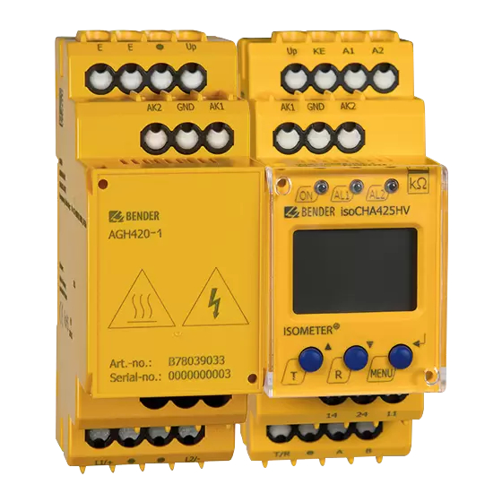
- Page 1 ISOMETER® isoCHA425HV with AGH420-1 Insulation monitoring device with coupling device for unearthed DC systems (IT systems) DC 0 V to 1000 V Suitable for DC charging stations according to CCS or CHAdeMO Software version: D0624 V1.xx isoCHA425HV_D00404_00_M_XXEN / 10.2020 Manual EN...
- Page 2 Service and support for Bender products First-level support Technical support Carl-Benz-Strasse 8 • 35305 Grünberg • Germany Telephone: +49 6401 807-760 0700BenderHelp * Fax: +49 6401 807-629 E-mail: support@bender-service.de Available on 365 days from 7.00 a.m. to 8.00 p.m. (MEZ/UTC +1) * Landline German Telekom: Mon-Fri from 9.00 a.m.
-
Page 3: Table Of Contents
Indication of important instructions and information ........5 1.2.1 Signs and symbols ......................5 Training courses and seminars.................5 Delivery conditions .......................5 Inspection, transport and storage ................6 Warranty and liability....................6 Disposal of Bender devices ..................6 Safety ..........................6 Function ....................7 Intended use ........................7 Device features ......................7 Functional description ....................8 2.3.1 and C in "CHd"... - Page 4 Wiring diagram ......................16 Commissioning ......................17 Operation of the device ..............19 Displays and buttons ....................19 Menu overview ......................20 "AL" menu ........................21 4.3.1 Setting response value ..................... 21 "out" menu........................21 4.4.1 Relay mode configuration ..................21 4.4.2 Relay alarm assignment "r1"...
-
Page 5: General Instructions
Training courses and seminars www.bender.de/en -> Know-how -> Seminars. Delivery conditions The conditions of sale and delivery set out by Bender apply. These can be obtained from Bender in printed or electronic format. The following applies to software products: "Softwareklausel zur Überlassung von Standard- Software als Teil von Lieferungen, Ergänzung und Änderung der Allgemeinen Lieferbedingungen für Erzeugnisse und... -
Page 6: Inspection, Transport And Storage
• Non-observance of technical data. • Repairs carried out incorrectly. • Use of accessories and spare parts not recommended by Bender. • Catastrophes caused by external influences and force majeure. • Mounting and installation with device combinations not recommended by the manufacturer. -
Page 7: Function
• Measured value indication via a multifunctional LC display • Fault memory can be activated • RS-485 (galvanically separated) including the following protocols: – BMS interface (Bender measuring device interface) for data exchange with other Bender compo- nents – Modbus RTU –... -
Page 8: Functional Description
Function Functional description The ISOMETER® is designed for use in DC charging stations according to CHAdeMo standard or Combined Charging System (CCS) and can be set to the respective mode in the "SEt" menu via the Mode parameter. It measures the total insulation resistance R as well as the one-sided insulation re- sistance R , the system leakage capacitance C... -
Page 9: Fault Location R
ISOMETER® isoCHA425HV with AGH420-1 2.3.3 Fault location R% From U > DC 20 V the fault location R% is calculated for two-pole insulation faults R up to 500 kΩ ("CHd" mode 150 kΩ). The value -100 % indicates a single-pole insulation fault at L2/-, 0 % indicates a symmetrical insulation fault and +100 % indicates a single-pole insulation fault at L1/+. -
Page 10: Stop Mode
Function 2.3.9 Stop mode For applications where the ISOMETER® is not needed and the measuring pulse interferes with other measuring functions, it can be set to stop mode via the Modbus protocol or by pressing and holding the external test/reset button ("T/R"). The measuring pulse generator is turned off and the measuring function is deactivated. -
Page 11: System Connection Test L1/+ And L2
ISOMETER® isoCHA425HV with AGH420-1 2.3.17 System connection test L1/+ and L2/- The system connection test configurable in the "SEt"/"nEt" menu checks the connection between termi- nals L1/+ and L2/- via the monitored system. For correct operation of the ISOMETER® the monitored system must have a low-ohmic (<... -
Page 12: Alarm Assignment Of The Alarm Relays K1/K2
Function 2.3.18 Alarm assignment of the alarm relays K1/K2 The messages "Device error", "Insulation fault", "Undervoltage/overvoltage fault, "Device test" or "Device start with alarm" can be assigned to the alarm relays via the "out" menu. An insulation fault is indicated by the messages "+R1", "-R1", "+R2" and "-R2". The messages "+R1" and "+R2" indicate an insu- lation fault assigned to conductor L1/+, and the messages "-R1"... -
Page 13: Password Protection (On, Off)
2.3.25 Interface/protocols The ISOMETER® uses the serial hardware interface RS-485 with the following protocols: • BMS The BMS protocol is an essential component of the Bender measuring device interface (BMS bus protocol). Data is transferred using ASCII characters. • Modbus RTU Modbus RTU is an application layer messaging protocol and it provides master/slave commu- nication between devices that are connected altogether via bus systems and networks. - Page 14 Function The parameter address, baud rate and parity for the interface protocols are configured in the "out" menu. With "Adr = 0", the menu entries "Baud rate" and "Parity" are not shown in the menu and the IsoData protocol is activated. With a valid bus address (i.e. not equal to 0), the menu item "Baud rate" is dis- played in the menu.
-
Page 15: Dimensions And Mounting
ISOMETER® isoCHA425HV with AGH420-1 Dimensions and mounting Dimensions 36 mm Abb. 3–1 Dimensions in mm Mounting Click & Click! Variant A: DIN rail mounting Variant B: screw mounting The front plate cover can be opened at the lower part marked with an arrow. isoCHA425HV_D00404_00_M_XXEN / 10.2020... -
Page 16: Wiring Diagram
Dimensions and mounting Wiring diagram DC + DC - Test / Reset GND AK2 > 800 V 30 mm 30 mm AGHxxx MENU L1/+ L2/- COM465IP L1/+ L2/- RS-485 J-Y(St)Y 2x0,6 For conductor cross sections for wiring, refer to "Technical data". Legend Terminal Connections... -
Page 17: Commissioning
ISOMETER® isoCHA425HV with AGH420-1 Terminal Connections 11, 14 Connection to alarm relay "K1" 11, 24 Connection to alarm relay "K2" A, B RS-485 communication interface with connectable terminating resistor. Example: Connection of a BMS Ethernet gateway COM465IP * For UL applications: Use 60/75 °C copper lines only! UL and CSA applications require the supply voltage U to be protected via 5 A fuses. - Page 18 Operation of the device isoCHA425HV_D00404_00_M_XXEN / 10.2020...
-
Page 19: Operation Of The Device
ISOMETER® isoCHA425HV with AGH420-1 Operation of the device Displays and buttons Function Device front green - on yellow - alarm yellow - alarm Arrow-up button: navigate up in the menu. Test button (press > 1.5 s) By pressing and holding the test button, the display elements are shown. Arrow-down button: navigate down in the menu. -
Page 20: Menu Overview
Operation of the device Menu overview Measured value display Menu selection Parameter input > < 1.5 s > > . . . 1.5 s 1.5 s < t > 5 Min. < > 1.5 s R [k ] C [µF] U L1 L2 [V ] UL1 [V ] <... -
Page 21: Al" Menu
ISOMETER® isoCHA425HV with AGH420-1 "AL" menu Legend of the tables below: ¥ FAC= factory settings, CS: customer settings, ( ) = customer settings that are not affected by FAC, : LED off, : LED ¡ flashes, : LED on 4.3.1 Setting response value The two parameters "R1"... -
Page 22: Fault Memory Configuration
Operation of the device K1 "r1" K2 "r2" LEDs Alarm description Display Display 1 Err 2 Err Device error E.xx ¥ ¥ ¥ Prewarning R1 ¡ +R1 < Ω +R1 < Ω Fault R at L1/+ Prewarning R1 ¡ -R1 < Ω -R1 <... -
Page 23: T" Menu
≥ DC 100 V) on U System connection test on : if U ≤ DC 100 V on U on U: if U > DC 100 V S.Ct Device test at device start Restore factory settings For Bender Service only isoCHA425HV_D00404_00_M_XXEN / 10.2020... -
Page 24: Measured Value Display And History Memory
Operation of the device Measured value display and history memory The pulse symbol indicates a present measured value. If this symbol does not appear, the measurement is still running and the latest valid measured value will be displayed. The symbols "<" or ">" will be dis- played additionally to the measured value when a response value has been reached or violated, or the measured value is below or above the measuring range. -
Page 25: Data Access Using The Bms Protocol
ISOMETER® isoCHA425HV with AGH420-1 Data access using the BMS protocol The BMS protocol is an essential component of the Bender measuring device interface (BMS bus proto- col). Data is transferred using ASCII characters. BMS channel no. Operation value Alarm Prewarning R1... - Page 26 Data access using the Modbus RTU protocol isoCHA425HV_D00404_00_M_XXEN / 10.2020...
-
Page 27: Data Access Using The Modbus Rtu Protocol
ISOMETER® isoCHA425HV with AGH420-1 Data access using the Modbus RTU protocol Requests to the ISOMETER® can be made using the function code 0x03 (read multiple registers) or the command 0x10 (write multiple registers). It generates a function-related answer and sends it back. Reading out Modbus registers from the ISOMETER®... -
Page 28: Response Of The Isometer® To The Master
Data access using the Modbus RTU protocol Byte Name Example Byte 6 Number of data bytes 0x02 Byte 7, 8 Data 0x0002 Byte 9, 10 CRC16 Checksum 0x9F7A 6.3.2 Response of the ISOMETER® to the master Byte Name Example Byte 0 ISOMETER®... -
Page 29: Modbus Register Assignment Of The Isometer
ISOMETER® isoCHA425HV with AGH420-1 Modbus register assignment of the ISOMETER® Depending on the device state, the information in the registers is either the measured value without alarm, the measured value with alarm 1, the measured value with alarm 2 or only the device error. Register Measured value Device error... - Page 30 Modbus register assignment of the ISOMETER® Register Property Description Format Unit Value range 3005 Prewarning value resistance measurement "R1" UINT 16 kΩ R2 … 600 3006 Reserved 3007 Alarm value resistance measurement "R2" UINT 16 kΩ 5 … R1 3008 Activation alarm value undervoltage "U<"...
-
Page 31: Device-Specific Data Type Of The Isometer
ISOMETER® isoCHA425HV with AGH420-1 Register Property Description Format Unit Value range 3024 Test of the system connection during device test "nEt" UINT 16 0 = off 1 = on 2 = on U 3025 Device test at device start "S. Ct" UINT 16 0 = off 1 = on... -
Page 32: Measured Values
Modbus register assignment of the ISOMETER® 7.1.2 Measured values Each measured value is available as a channel and consists of 8 bytes (4 registers). The first measured value register address is 1000. The structure of a channel is always identical. Content and number de- pend on the device. -
Page 33: At&T = Alarm Type And Test Type (Internal/External)
ISOMETER® isoCHA425HV with AGH420-1 7.1.2.2 AT&T = Alarm type and test type (internal/external) Description External test Internal Reserved Reserved Reserved Alarm Error test No alarm Prewarning Device error Alarm type Reserved Warning Alarm Reserved … … … Reserved Reserved No test Internal test Test External test... -
Page 34: R&U = Range And Unit
Modbus register assignment of the ISOMETER® 7.1.2.3 R&U = Range and unit Description Invalid (init) No unit Ω Baud Unit °C °F Second Minute Hour Month Actual value The actual value is lower Range of validity The actual value is higher Invalid value •... -
Page 35: Alarm Assignment Of The Relays
ISOMETER® isoCHA425HV with AGH420-1 7.1.3 Alarm assignment of the relays Several alarms can be assigned to each relay. For the assignment of each relay, a 16-bit register is used with the bits described below. The following table applies to relay 1 and relay 2, in which "x" stands for the relay number. - Page 36 Modbus register assignment of the ISOMETER® Value Measured value description/alarm message operating message Note 78 (0x4E) Overvoltage 82 (0x52) Capacitance Measured value in F 86 (0x56) Insulation fault Impedance Z 101 (0x65) Connection system 102 (0x66) Connection earth 115 (0x73) Device error Malfunction ISOMETER®...
-
Page 37: Isodata Data String
ISOMETER® isoCHA425HV with AGH420-1 IsoData data string In IsoData mode, the ISOMETER® continuously sends the entire data string with a cycle time of approxi- mately 1 s. Communication with the ISOMETER® within this mode is not possible. No additional trans- mitters may be connected to the RS-485 bus cable. - Page 38 Technical data isoCHA425HV_D00404_00_M_XXEN / 10.2020...
-
Page 39: Technical Data
ISOMETER® isoCHA425HV with AGH420-1 Technical data ( )* = factory settings Insulation coordination acc. to IEC 60664-1/IEC 60664-3 Definitions: Supply circuit (IC2) ..................................A1, A2 Output circuit (IC3) ..................................11, 14, 24 Control circuit (IC4) ..........................Up, KE, T/R, A, B, AK1, GND, AK2 Rated voltage ....................................240 V Overvoltage category ....................................III Rated impulse voltage:... - Page 40 Technical data Mode CCS (dc) Permissible system leakage capacitance C ............................. ≤ 5 µF Measuring and display range R ............................1 kΩ ... 2 MΩ Measurement uncertainty R /relative uncertainty R ....................... ±15 %, ±2 kΩ Measuring and display range C ..............................0 ...
- Page 41 ISOMETER® isoCHA425HV with AGH420-1 Cable length (9.6 kBits/s) ................................ ≤ 1 200 m Cable: twisted pairs, shield connected to PE on one side ..................min. J-Y(St)Y 2 x 0.6 Terminating resistor......................120 Ω (0.25 W), internal, can be connected Device address, BMS bus, Modbus RTU ..........................3…90 (3)* Switching elements Switching elements ........................
- Page 42 Technical data Technical data AGH420-1 Insulation coordination acc. to IEC 60664-1/IEC 60664-3 Definitions: Measuring circuit (IC1) ................................L1/+, L2/- Control circuit (IC2) ..............................AK1, GND, AK2, Up, E Rated voltage ....................................1 000 V Overvoltage category .....................................III Rated impulse voltage: IC1/IC2 ....................................... 8 kV Rated insulation voltage: IC1/IC2..
-
Page 43: Standards, Approvals And Certifications
ISOMETER® isoCHA425HV with AGH420-1 Flexible without ferrules ..............................0.75…2.5 mm Flexible with ferrules with/without plastic sleeve ......................0.25…2.5 mm Multi-conductor flexible with TWIN ferrules with plastic sleeve..................0.5…1.5 mm Opening force ....................................50 N Test opening, diameter ................................2.1 mm Single cables for terminals Up, AK1, GND, AK2: Cable length (AGH420-1 ... -
Page 44: Declaration Of Conformity
Technical data Declaration of Conformity isoCHA425HV_D00404_00_M_XXEN / 10.2020... - Page 45 ISOMETER® isoCHA425HV with AGH420-1 isoCHA425HV_D00404_00_M_XXEN / 10.2020...
- Page 46 Nachdruck und Vervielfältigung Reprinting and duplicating nur mit Genehmigung des Herausgebers. only with permission of the publisher. Bender GmbH & Co. KG Bender GmbH & Co. KG Postfach 1161 • 35301 Grünberg • Deutschland PO Box 1161 • 35301 Grünberg • Germany Londorfer Str.
Need help?
Do you have a question about the ISOMETER isoCHA425HV and is the answer not in the manual?
Questions and answers