Bender ISOMETER isoCHA425HV User Manual
Insulation monitoring device with coupling device
Hide thumbs
Also See for ISOMETER isoCHA425HV:
- Manual (52 pages) ,
- Quick start manual (13 pages) ,
- Manual (46 pages)
Table of Contents
Advertisement
Quick Links
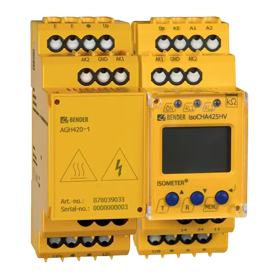
ISOMETER® isoCHA425HV & AGH420-1
Isolationsüberwachungsgerät mit Ankoppelgerät für ungeerdete DC-
Systeme (IT-Systeme) DC 0 V bis 1000 V
Insulation monitoring device with coupling device for unearthed
DC systems (IT systems) DC 0 V up to 1000 V
isoCHA425HV_D00404_04_Q_DEEN/ 02.2023
Kurzanleitung/Quickstart DE/EN
Advertisement
Table of Contents

Related Manuals for Bender ISOMETER isoCHA425HV


Summary of Contents for Bender ISOMETER isoCHA425HV
- Page 1 ISOMETER® isoCHA425HV & AGH420-1 Isolationsüberwachungsgerät mit Ankoppelgerät für ungeerdete DC- Systeme (IT-Systeme) DC 0 V bis 1000 V Insulation monitoring device with coupling device for unearthed DC systems (IT systems) DC 0 V up to 1000 V isoCHA425HV_D00404_04_Q_DEEN/ 02.2023 Kurzanleitung/Quickstart DE/EN...
- Page 2 Part of the device documentation in addition to ben dieser Kurzanleitung die „Sicherheitshin- this quickstart is the enclosed “Safety instructi- weise für Bender-Produkte“ und das dazugehö- ons for Bender products“ and the manual, rige Handbuch, herunterladbar unter https:// which can be downloaded from https://www.
- Page 3 ISOMETER® isoCHA425HV & AGH420-1 Merkmale CHAdeMO Mode "CHd" und "CHA" Features CHAdeMO mode "CHd" and CHA" Mode CHAdeMO Maximale Netzableitkapazität 1,6 µF je Leiter Maximum system leakage capacitance 1.6 μF per conductor Erkennung von Isolationsfehlern im Netzspannungsbereich Detection of insulation faults in the system voltage range ...
-
Page 4: Montage
ISOMETER® isoCHA425HV & AGH420-1 Montage Mounting Montage auf Hutschiene / DIN rail mounting Schraubbefestigung / Screw mounting Click & Click! Anschlussbild Wiring diagram DC + DC - Test / Reset GND AK2 > 800 V 30 mm 30 mm AGHxxx MENU COM465IP L1/+... -
Page 5: Wiring Diagram Legend
ISOMETER® isoCHA425HV & AGH420-1 Legende zum Anschlussbild Wiring diagram legend Klemme/ Anschlüsse Connections Terminal A1, A2 Anschluss an die Versorgungsspannung U über Connection to the supply voltage U via a fuse: Schmelzsicherung: If supplied from an IT system, both lines have to be protected by a Bei Versorgung aus IT-System beide Leitungen absichern.* fuse.* E, E, KE... -
Page 6: Menü-Übersicht
ISOMETER® isoCHA425HV & AGH420-1 Menü-Übersicht Menu overview Messwertanzeige Menüauswahl Parametereingabe Measurement display Menu selection Parameter selection > < 1.5 s > > . . . 1.5 s 1.5 s < t > 5 Min. < > 1.5 s R [k ] C [µF] U L1 L2 [V ] UL1 [V ]... -
Page 7: Display Elements
ISOMETER® isoCHA425HV & AGH420-1 Display-Elemente Display elements Funktion Gerätefront/ Device front Function grün - On green - On gelb - Alarm yellow - Alarm gelb - Alarm yellow - Alarm Aufwärts-Taste Up button Test-Taste (> 1,5 s drücken) Test button (press > 1.5 s) Bei gedrückter Test-Taste werden die By pressing and holding the test Display-Elemente angezeigt. -
Page 8: Technische Daten
ISOMETER® isoCHA425HV & AGH420-1 Technische Daten Technical data Isolationskoordination nach IEC 60664-1/IEC 60664-3 Insulation coordination acc. to IEC 60664-1/IEC 60664-3 Bemessungsspannung ..............240 V Rated voltage ................240 V Überspannungskategorie ..............III Overvoltage category ..............III Versorgungsspannung Supply voltage Versorgungsspannung U ....AC 100…240 V/ DC 24…240 V Supply voltage U ...... - Page 9 ISOMETER® isoCHA425HV & AGH420-1 Mode CHAdeMO (CHd und CHA) Mode CHAdeMO (CHd and CHA) Netzspannung U ......Messbetrieb erst ab U System voltage U ..... Measuring mode only from U ≥ 50 V ≥ 50 V Zulässige Netzableitkapazität C ......je Leiter ≤ 1,6 µF Permissible system leakage capacitance C ..
- Page 10 ISOMETER® isoCHA425HV & AGH420-1 Federklemmen Push-wire terminals Nennstrom ................≤ 10 A Nominal current ..............≤ 10 A Querschnitt ..............AWG 24…14 Cross section ..............AWG 24…14 Abisolierlänge .................10 mm Stripping lenght ..............10 mm Starr ................0,2…2,5 mm Rigid ................0.2…2.5 mm Flexibel ohne Aderendhülse.
-
Page 11: Eu-Konformitätserklärung
ISOMETER® isoCHA425HV & AGH420-1 EU Konformitätserklärung EU Declaration of Conformity Hiermit erklärt die Bender GmbH & Co. KG, dass das Bender GmbH & Co. KG hereby declares that the de- unter die Funkrichtlinie fallende Gerät der Richtlinie vice covered by the Radio Directive complies with Di- 2014/53/EU entspricht. - Page 12 Nachdruck und Vervielfältigung Reprinting and duplicating nur mit Genehmigung des Herausgebers. only with permission of the publisher. Bender GmbH & Co. KG Bender GmbH & Co. KG Postfach 1161 • 35301 Grünberg • Deutschland PO Box 1161 • 35301 Grünberg • Germany Londorfer Str.
Need help?
Do you have a question about the ISOMETER isoCHA425HV and is the answer not in the manual?
Questions and answers