Table of Contents
Advertisement
Quick Links
Manual
ISOMETER®
iso685–D–P
iso685W–D–P
iso685–S–P
iso685W–S–P
Insulation Monitoring Device
with integrated locating current injector
for IT AC systems with galvanically connected
rectifiers and inverters and for IT DC systems
Software version: D440 V 1.25 | D439 V 1.25
iso685-x-P_D00170_08_M_XXEN/09.2019
Advertisement
Table of Contents

Subscribe to Our Youtube Channel
Related Manuals for Bender ISOMETER iso685W-D-P


Summary of Contents for Bender ISOMETER iso685W-D-P
- Page 1 Manual ISOMETER® iso685–D–P iso685W–D–P iso685–S–P iso685W–S–P Insulation Monitoring Device with integrated locating current injector for IT AC systems with galvanically connected rectifiers and inverters and for IT DC systems Software version: D440 V 1.25 | D439 V 1.25 iso685-x-P_D00170_08_M_XXEN/09.2019...
- Page 2 Email: info@bender.de Web: www.bender.de Customer service: Service hotline: 0700-BenderHelp (Telephone and Fax) Carl-Benz-Straße 8 • 35305 Gruenberg • Germany © Bender GmbH & Co. KG Tel.:+49 6401 807-760 All rights reserved. Fax:+49 6401 807-629 Reproduction only with permission of the publisher.
-
Page 3: Table Of Contents
Table of contents 1. Important information ................7 4.5.4 Character input ...........16 4.5.5 Multiple selection in the device menu . - Page 4 Table of contents 7.4 Recommissioning ........... . 33 (1.10) Outputs .
- Page 5 Table of contents (4.0) Control ........... 52 10.
- Page 6 Table of contents 12.5 EDSsync ............71 12.5.1 Preparing the devices in an interconnection .
-
Page 7: Important Information
1.2 Technical support 1.2.1 End customer support and advice This manual is intended for qualified personnel working in electrical Technical support by phone or e-mail for all Bender products engineering and electronics! • Questions concerning specific customer applications • Commissioning •... -
Page 8: Training Courses
• Old electrical and electronic equipment from users other than private households Sale and delivery conditions can be obtained from Bender in printed or electronic format. which was introduced to the market after 13 August 2005 must be taken back by the manufacturer and disposed of properly. -
Page 9: Safety Instructions
Part of the device documentation in addition to this manual is the enclosed "Safety in- Installation inside a control cabinet structions for Bender products". If the ISOMETER® is installed inside a control cabinet, the insulation fault message must be audible and/or visible to attract attention. -
Page 10: Function
• Remote diagnosis via the Internet (made available by Bender Service only) extensive DC-supplied loads (such as rectifiers, inverters, variable-speed drives). • RS-485/BS (Bender sensor bus) for data exchange with other Bender devices via Modbus RTU protocol 3.2.2 Special ISOMETER® characteristics •... -
Page 11: Function Description
Function Function 3.3 Function description The ISOMETER® has an internal system isolating switch, which makes it possible to opera- te several ISOMETER®s in coupled IT systems. For this purpose, the ISOMETER®s are con- The insulation monitoring device continuously monitors the entire insulation resistance nected via an Ethernet bus. -
Page 12: Compatibility With Eds-Devices
3.5 Interfaces • Communication protocol Modbus TCP • Communication protocol Modbus RTU • BCOM for communication of Bender devices via Ethernet • BS bus for communication of Bender devices (RS-485) • BB bus (Bender backbone bus) • isoData for recording and managing measured values •... -
Page 13: Geräteübersicht
4. Geräteübersicht Geräteübersicht 4.1 Dimensions 4.2 Device variants iso685(W)-D… The iso685 variant features a high-resolution graphic LC display and operating controls for direct operation of the device functions. isoxx685(W)-D… It cannot be combined with an FP200. iso685(W)-S… Device version iso685-S-P features neither a display nor operating controls. -
Page 14: Connection And Panel
Front Rear Connection top REMOTE Control panel Connction bottom REMOTE interface to connect the FP200(W) * Optional expansion interface for Bender products Bottom Multifunctional I/O interface (see „Connection of the X1 interface“) ETH (X2) Ethernet interface Switchable terminating resistor for termination of the RS-485 interface... -
Page 15: Display Elements And Device Buttons
Geräteübersicht Geräteübersicht 4.4 Display elements and device buttons 4.4.2 device buttons You can adjust the device settings in the respective menu using the menu buttons. De- pending on the menu entry, one of the options displayed below is assigned to the but- tons. -
Page 16: Operating And Navigating
Geräteübersicht Geräteübersicht 4.5 Operating and navigating 4.5.4 Character input Use the (forward) and (backward) 4.5.1 Menu selection Ethernet x.3.2 buttons to select a character from the dis- Activate the menu by pressing the play. To enter the next character, use the IT system "MENU"... -
Page 17: Mounting
5. Mounting Mounting 5.1 Common information 5.2 Mounting spaces Only qualified personnel are permitted to carry out the work necessary to install, commission and run a device or system. 20 mm Read the manual before you begin to mount, connect, and commission the unit. -
Page 18: Screw Mounting
Mounting Mounting 5.3 Screw mounting 5.4 DIN rail mounting 1. Fix the three mounting clips delivered with the device (two of them packed 1. Fix the three mounting clips delivered with the device (two of them packed separately) manually or using a tool, as illustrated below. separately) manually or using a tool, as illustrated below. -
Page 19: Connection
6. Connection Connection 6.1 Connection requirements Provide line protection! According to DIN VDE 0100-430, a line protection shall be provided for the In accordance with VDE 0100, only qualified personnel are permitted to supply voltage. carry out the work necessary to install, commission and run a device or CAUTION Risk of injury from sharp-edged terminals! system. -
Page 20: Connection To A 3(N)Ac System
Connection Connection 6.2 Connection to a 3(N)AC system 6.3 Connection to an AC system Risk of injury, fire and damage to property due to a short circuit! Risk of injury, fire and damage to property due to a short circuit! According to DIN VDE 0100-430, devices used to protect against a short According to DIN VDE 0100-430, devices used to protect against a short circuit when terminals "L1/+", "L2"... -
Page 21: Connection To A Dc System
Connection Connection 6.4 Connection to a DC system 6.5 Connection to the supply voltage Danger of damage to property due to faulty connections! Risk of injury, fire and damage to property due to a short circuit! The device may be damaged if it is simultaneously connected to the sup- According to DIN VDE 0100-430, devices used to protect against a short ply voltage via the "X1"... -
Page 22: Connection To The X1 Interface
Connection Connection 6.6 Connection to the X1 interface 6.7 Connection to the ethernet interface ETH I1 I2 I3 A B RS-485 RS-485 RJ45 I1 I2 Deactiv. RESET TEST Device Connection with standard patch cable (RJ45/no crossover cable) to other ISOMETER®s or interconnection of several ISOMETER®s in STAR topology via a switch. -
Page 23: Position The Terminal Covers And Click Them Into Place
Fix the terminal covers to the provided enclosure recesses until they snap into place. The BB bus is an interface that enables Bender devices to communicate with each other. The BB bus can be used with an ISOMETER® and one or more EDS44x-S. For this purpose, the BB bus is installed at the rear side of both devices and afterwards, both devices are mounted next to each other on the DIN rail. -
Page 24: Connection Of Eds44X/Iom441 To The Isometer
Connection Connection 6.11 Connection of EDS44x/IOM441 to the ISOMETER® A maximum of 50 EDS44x devices with one IOM44 each can be connected to an ISOME- TER®. If one EDS and one IOM each are connected via the BB bus, another 49 EDS44x de- vices can be connected to the corresponding IOM441 via the RS-485 interface. -
Page 25: Connection Example Isometer® To Eds
Connection 6.11.1 Connection example ISOMETER® to EDS Load Load Load Load L1 L2 L3 L4 L5 L6 L7 L8 L9 L10 L11 L12 l1 l2 l3 l4 l5 l6 l7 l8 l9 l10 l11 l12 A1/+ A2/- L1/+ L3/- KE E K1 K2 K3 K4 K5 K6 K7 K8 K9 K10 K11 K12 k1 k2 k3 k4 k5 k6 k7 k8 k9 k10 k11 k12 11 12... -
Page 26: Connection To A 3(N)Ac System
Connection 6.11.2 Connection to a 3(N)AC system Load Load l1 l2 l3 l4 l5 l6 l7 l8 l9 l10 l11 l12 A1/+ A2/- L1/+ L3/- KE E k1 k2 k3 k4 k5 k6 k7 k8 k9 k10 k11 k12 11 12 EDS440 ISOSCAN®... -
Page 27: Connection To An Ac System
Connection 6.11.3 Connection to an AC system Load Load l1 l2 l3 l4 l5 l6 l7 l8 l9 l10 l11 l12 A1/+ A2/- L1/+ L3/- KE E k1 k2 k3 k4 k5 k6 k7 k8 k9 k10 k11 k12 9 10 11 12 EDS440 ISOSCAN®... -
Page 28: Connection To A Dc System
Connection 6.11.4 Connection to a DC system L– Load Load l1 l2 l3 l4 l5 l6 l7 l8 l9 l10 l11 l12 k1 k2 k3 k4 k5 k6 k7 k8 k9 k10 k11 k12 A1/+ A2/- L1/+ L3/- KE E 11 12 EDS440 ISOSCAN®... -
Page 29: System Structure
Connection 6.11.5 System structure AC 24 V DC 110 V Input Output A1/+ A2/- L1/+ L3/- KE E EDS441 EDS440 ISOSCAN® ISOSCAN® IT-System PGH ON >20 MΩ >20 MΩ R(an) 40kΩ/10kΩ Application example: monitoring of a control system with the ISOMETER® iso685-D-P and the EDS441-S iso685-x-P_D00170_08_M_XXEN/09.2019... -
Page 30: Commissioning
7. Commissioning Commissioning 7.1 General initial commissioning process ISOMETER® EDS44x ISOMETER® with EDS44x commissioning commissioning commissioning 1. Check that the ISOMETER® is properly connected to the system to be monitored. Run commissioning wiz- Set BS address on the Set EDS mode in the ISO- 2. -
Page 31: Initial Commissioning
Commissioning Commissioning 7.2 Initial commissioning 7.2.3 Setting system type By setting the system type, the insulation monitoring device can be optimally adapted to Check network function! the system to be monitored. The system type is essential information for the insulation When the device has been integrated into a network, the influence on the monitoring device in order to determine the insulation resistance correctly. -
Page 32: Setting Eds Current
Commissioning Commissioning 7.2.6 Setting EDS current 7.3 Commissioning of EDS Set the maximum locating current. Proceed as follows to put into operation an EDS after commissioning the ISOMETER®: EDS441: 1-5 mA 1. First, search for all available measuring channels. EDS440: 10-50 mA Menu path: Menu ->... -
Page 33: Recommissioning
Commissioning Commissioning 7.4 Recommissioning If the device has already been put into operation once, the self test will be carried out shortly after connecting the supply voltage. The commissioning wizard will not restart. You can restart the commissioning wizard using the following menu path: Menu ->... -
Page 34: Display
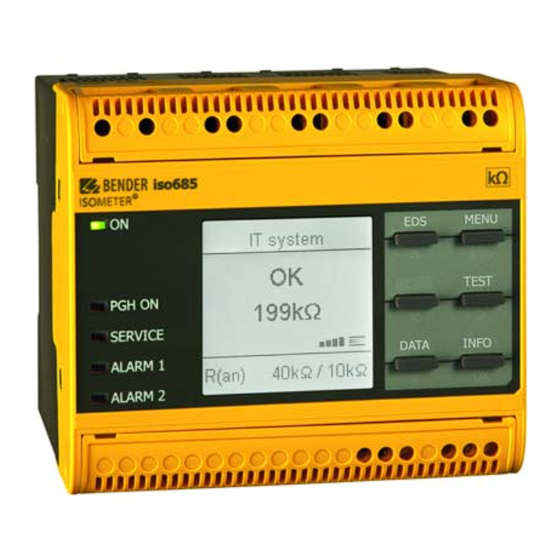
8. Display Display 8.1 Standard display 8.2 Fault display (active) During normal operation, the ISOMETER® displays the message "OK" and below, the cur- An active fault is displayed by rently measured insulation resistance. The upper part of the display turns orange and displays the fault message. Depending on the type of fault, the LEDs "ALARM 1", "ALARM 2"... -
Page 35: Fault Display (Inactive)
Display Display 8.3 Fault display (inactive) 8.4 Acknowledging a fault message An inactive fault is indicated by . If several faults have occurred, the number of faults In order to acknowledge the fault message and return to the ISOMETER®'s standard dis- will also be indicated. -
Page 36: Data-Isograph
Display Display 8.6 Data-isoGraph 8.8 ISOnet operation The isoGraph represents the chronological sequence of the insulation resistance over The ISOMETER® displays the message „ISOnet active“ when the ISOMETER® is in ISOnet time. This graphical representation can be displayed over the following time periods: mode but is not currently measuring. -
Page 37: Automatic Test
Display Display 8.10 Automatic test * Display for low-frequency measurements In the LAB procedure, the pulse can last up to one minute. Therefore, there If the ISOMETER® measures in ISOnet mode, the "ON" LED flashes and the measurement is no constant "changing" of the display symbols. The respective symbols progress bar in the lower right corner pulses. -
Page 38: Settings
9. Settings Settings 9.1 Menustructure 1. Alarm settings 1. Insulation alarm 1. Alarm 1 2. EDS 1. General 1. Current 2. Alarm 2 2. Mode 3. Memory 3. Use portable EDS 4. EDSsync 2. DC Alarm 1. Alarm 5. Scan for channels 2. -
Page 39: Settings In The Device Menu
Settings Settings 9.2 Settings in the device menu 3. Data meas. values 4. Control 1. TEST Representation of the menu items in the headings 2. Reset 3. Initial Measure The settings of the ISOMETER® are explained in the order of the device 4. -
Page 40: 3) Fault Memory
0.1…460 Hz. The DC alarm is triggered in the event of a DC offset voltage. •on Enables the Bender service to make customer-specific settings. •Customer-specific The DC alarm is NOT triggered in the event of a DC offset voltage. -
Page 41: Isoloop
Settings Settings (1.6) ISOloop The exemplary wiring diagram shows how the digital inputs can be wired. Schalten Sie die ISOloop-Funktion aktiv oder inaktiv: RS-485 RS-485 1. ISOloop: 2. Measured value subscription: I1 I2 RESET TEST Deactiv. Device (1.6.1) ISOloop Turns the function on or off. high (1.6.2) Measured value subscription active... -
Page 42: 2) Digital 2
Settings Settings (1.9.1.2) t(on) (1.10.1.1) TEST The response time t(on) after a switch-on signal can be set between 100 ms and 300 s. The functional test of the relay can be activated or deactivated. This only applies to the manual test and not to the cyclic device self test: (1.9.1.3) t(off) The manual test checks the switching function of the relay •on... -
Page 43: (1.10.2) Relais 2
Settings Settings (1.10.2) Relais 2 Function Description Refer to chapter 9.2 (1.10.1) “Relay 1”, page 42f. The status of the output changes in case of an earth fault in the direction •DC- alarm of DC when 75 % of the value are exceeded. This does not concern sym- (1.10.3) Digital 1 metrical faults. -
Page 44: (1.10.4) Digital 2
Settings Settings (1.10.3.3) Function 1 (1.10.6.1) Mode Refer to chapter 9.2 (1.10.1.3) “Function 1”, page 42f. The following values can be set for the operating mode of the analogue output (1.10.3.4) Function 2 Refer to chapter 9.2 (1.10.1.3) “Function 1”, page 42f. -
Page 45: (2.0) Eds (Insulation Fault Location)
Settings Settings Calculation of the insulation resistance using the analogue output: (2.1.1) Current Lower value Upper value Risk of malfunctions due to excessive locating current on sensitive ) * R Analogue Output A Analogue Output A system parts! 0 mA 20 mA The locating current flowing between the IT system and earth can cause 4 mA... -
Page 46: (2.1.3) Using A Portable Eds
Settings Settings (2.1.5) Scan for channels: Inactive insulation fault location The function determines how the "Scan Channels" process is triggered. (insulation measurement) New insulation fault A channel scan searches the BS and BB bus for existing (detected) EDS devices. These are No insulation fault Mode: auto/1 cycle continuously assigned to the Modbus registers internally. -
Page 47: (2.4) Group Settings
Settings Settings Multiple selection is possible. (2.4.1.1) Current transformer (CT) Set the used current transformer. All measuring channels are selected. •Select all No channel is selected. •No selection W…/WR…/WS…/ •Type A The current selection is inverted. •Invert selection W/WS8000 •Channel 1 (BS 2/1) A single channel is selected. -
Page 48: (2.4.2) Outputs
Settings Settings (2.4.2) Outputs (2.4.2.1.3) Function 1 Make settings for the outputs of the EDS and the IOM441-S. Up to three functions can be assigned to one output. The functions are linked to an OR operator: •Common relays •Channel relays Funktion 1 •Buzzers Funktion 2... -
Page 49: (2.4.3) Dig. Input
Settings Settings (2.4.2.3) Buzzers (2.4.2.7) Function 3 Select the buzzers that you would like to configure. Refer to “9.2 (2.4.2.1.3) Function 1”. (2.4.3) Dig. input All buzzers are selected. •Select all No buzzer is selected. •No selection Select the digital inputs of the EDS that you would like to configure: The current selection is inverted. -
Page 50: (2.5) Channel
Settings Settings (2.4.4.1) System type (2.4.4.4) Fault memory Faults that only occur temporarily can be saved. Settings made to this menu item will only have an effect on connected After eliminating the cause of fault, alarm messages remain stored until a •on EDS460 and NOT on EDS44x devices. -
Page 51: (2.6.2) Channel Relays
In this menu, each digital output can be configured. Also refer to “9.2 (2.4.2.4) Digital out- (2.9) Service put”. The service menu can only be accessed by Bender service staff. (2.6.4.1) TEST Refer to “9.2 (2.4.2.1.1) TEST”. (2.6.4.2) Function 1 Refer to “9.2 (2.4.2.1.3) Function... -
Page 52: (3.0) Data Measured Values
Settings Settings (3.0) Data measured values (4.4) EDS The ISOMETER® stores certain measured values for a specific period of time. You can view Starts an insulation fault location process on the connected EDS device thes data at the "Data meas. values" menu item. Navigate through the different views (4.5) Device: using the buttons:... - Page 53 Settings Settings (6.2.3) Summer time Set whether the device can be parameterised externally via Modbus or web server. Dis- playing and reading out data via Modbus and web server is always possible, regardless of Summer time can be considered in the following settings: this setting.
- Page 54 If a DNS server is used, enter the server's IP address. For questions regarding the configu- (6.3.5) RS-485 ration of a DNS server, contact your network administrator. Set the parameters for communication with other devices via the Bender sensor bus. (6.3.2.6) Domain Selecting an RS-485 protocol 1.
- Page 55 Enter a 4-digit Service Profile PIN 1. Profile: Activation of special customer profiles by Bender. The device is first configured by the Bender service and the configuration is saved in a service profile. Activating this profile causes a warning message. The customer can activate it as a customer-specific profile by entering a Service Profile PIN.
- Page 56 – Easy and fast parameterisation of the device menu item "Allow" must have been set in the "Write access" menu. – Easy assignment and editing options of device texts • Maintenance – Data storage of specific events for fast support by the Bender service iso685-x-P_D00170_08_M_XXEN/09.2019...
- Page 57 Device communication Device communication 10.4.3 User interface 10.4.4 Menu structure The web menu is located on the left side of the browser window. Activated menu items are either highlighted in YELLOW or written in YELLOW. Use the scroll bar on the right side to display further menu items.
- Page 58 Device communication Device communication 10.4.5 Parameter changes 10.4.5.3 Error detection in case of incorrect entry In some cases, the system expects certain characters to be entered, for example, CAPITAL 10.4.5.1 Display of parameters in standard versions LETTERS. In case of an incorrect entry, the corresponding field is coloured in RED. Inputs are located horizontally (orange frame) and the corresponding parameters ver- tically (blue frame).
- Page 59 Device communication Device communication 10.4.6 Changing parameters in the web browser 10.4.7 Changing parameters in the device menu when the web browser is open Changed values are highlighted in YELLOW in the input field (see fig. 2.1). Changes can If values are changed in the iso685 device menu, the changed values are not au- be made via drop-down menu, value input or text input.
- Page 60 The optimum cable routing for the BS bus is a double-terminated bus topology. The The BS bus is used to extend Bender measuring devices (e.g. ISOMETER®) It is an RS-485 in- length of the branch line is limited to 1 m. These branch lines do not have to be terface with a specially developed protocol for Bender devices.
- Page 61 BMS protocol. To evaluate the data by means of a PC or laptop, an USB/RS232-RS485 interface converter are required. Contact Bender Service to receive this device. Interface data: • The RS-485 interface, galvanically isolated from the device electronics •...
- Page 62 Device communication 10.7.1 isoData-protocol table Description Length [Bytes] Value Unit Example string Mode Data packet start character for modes 2 and 3 Data packet start character 0x02 0x02 for mode 1 Available Bitmask Dependent on the fields included. (Bitmask) FFFFFFFF Date Current date dd.mm.yy...
- Page 63 Device communication Description Length [Bytes] Value Unit Example string Mode Voltage between phase L2 and PE. Voltage U (VRMS) L2-PE 1234 RMS value, Note: always signed with '+' Voltage between phase L3 and PE. Voltage U (VRMS) L3-PE 1234 RMS value, Note: always signed with '+' Quality of measured value 0 % = Poor quality Measurement quality...
- Page 64 Device communication Description Length [Bytes] Value Unit Example string Mode 0 == No alarm Alarm message Insualtion fault 1 == Alarm 1 Number Brief overview 2 == Alarm 2 3 == Alarm 1 + Alarm 2 Temperature in device Temperature value preceeded by '+' or '-' sign °C +100 System frequency...
- Page 65 11. Insulation fault location Insulation fault location 11.1 General description An additional function of the ISOMETER® in combination with the EDS is the selective in- sulation fault location. The insulation faults detected in the IT system by the ISOMETER® can be located by means of an EDS and a measuring current transformer. For further information regarding the function principle of the insulation fault location, refer to chapter 3.4 „Insulation fault location“.
- Page 66 12. Special functions for coupled IT systems Special functions for coupled IT systems 12.1 Particularities when monitoring coupled IT systems 12.2 System isolation via digital input with two coupled systems When using ISOMETER®s in IT systems, make sure that only one active ISOMETER® is con- nected in each interconnected system.
- Page 67 Special functions for coupled IT systems Special functions for coupled IT systems 12.3 System isolation via ISOnet 12.3.1 Systempictures The ISOnet function ensures via an Ethernet connection that only one ISOMETER® of the interconnection is active when several ISOMETER®s are connected to an IT system. For several ISOMETER®s to be able to measure in the same ISOnet interconnection, the settings for the BCOM system name and the BCOM subsystem have to be the same.
- Page 68 Special functions for coupled IT systems Special functions for coupled IT systems 12.3.2 Configuration and function 12.4 ISOloop For the ISOnet function, the following settings are made in the menu: Alarm settings Ring systems are a special type of coupled systems in which all systems can be coupled ->...
- Page 69 The basis of the ISOloop function is the combination of several ISOMETER®s to form an in- terconnection. The grouping of up to 10 ISOMETER®s is carried out with a separate soft- ware, the BCOM Group Manager. The program can be downloaded from the Bender website at www.bender.de/service-support/downloads or via the web server ("Menu" >...
- Page 70 Special functions for coupled IT systems Special functions for coupled IT systems The "Connection List" must contain all connections that exist in the installation. The follo- 12.4.2.3 Transferring the configuration file to an ISOMETER® wing figure shows the connections for the above example. The configuration file is installed via the web user interface of the iso685-x-P device in the browser of a computer in the network.
-
Page 71: Edssync
Special functions for coupled IT systems Special functions for coupled IT systems After completion, the file is available for download in the download area of each It is limited by the ISOMETER® depending on the settings. The insulation fault is selec- device: tively located by means of the EDS and the measuring current transformer connected to it. -
Page 72: Creating Groups With The Bcom Group Manager
BCOM manual (D00256) at www.bender.de/service-support/downloads. 12.5.2 Creating groups with the BCOM Group Manager The BCOM Group Manager provides help for creating ISOMETER® groups. Open the pro- gram and select EDSsync mode. -
Page 73: Activating The Function On The Isometer
Special functions for coupled IT systems Special functions for coupled IT systems After all settings of the group have been made, the configuration file must be saved. 7. Select target folder "group" (1.) 8. Select file "grp_0101.cfg" in the respective folder of your source PC (2.) 9. -
Page 74: Alarm Messages
13. Alarm messages 13.1 Measured value alarms Alarm messages are activated directly after switching on and can occur immediately. Alarm message Description Measures LED indicators An insulation fault exists. The insulation resistance falls • Observe insulation resistance in the monitored system Insulation fault "ALARM 1"... -
Page 75: Isonet
Internal device error • Switch the supply voltage off and on "SERVICE" is lit • Contact Bender service • Check insulation fault and eliminate fault of DC compo- DC offset voltage There is a DC offset voltage in the system. -
Page 76: Isoloop
Alarm messages 13.4 ISOloop These messages only become active after activating the ISOloop function. Alarm message Description Measures LED indicators • Make sure that all devices in the group to be configured The ISOloop group configuration is not uniform for all are able to communicate (correctly set and BCOM and ISOloop configuration is not devices in the group or one of the devices has no configura-... -
Page 77: Edssync
Alarm messages Alarm message Description Measures LED indicators • Check wiring of the measuring current transformers One measuring current transformer has not been con- • Check device function Interference CT connection nected correctly or does not work. • Start new search for EDS channels •... -
Page 78: Technical Data
– – – – tings. If no settings have been made by the Bender service, the profile has the same parameters as the "Power circuits" profile. For response times, refer „Device profiles“ at the follwing sections. Switching between profiles * Low-frequency system voltages When switching a profile, the value of R is reset. -
Page 79: Diagrams
Technical data Technical data 14.2 Diagrams 14.2.1 Response time profile power circuits 14.2.3 Response time generator profile Response time depending on response value and system leakage capacitance Response time depending on response value and system leakage capacitance acc. to IEC 61557-8 (U = 690 V, f = 50 Hz) measuring range <... -
Page 80: Response Time Inverter > 10 Hz Profile
Technical data Technical data 14.2.5 Response time inverter > 10 Hz profile 14.2.7 Response time DC alarm Response time depending on response value and system leakage capacitance Typical response times DC alarm at R depending on the measurement profile acc. to IEC 61557-8 (U = 690 V, f = 50 Hz) measuring range <... -
Page 81: Factory Settings Iso685-X-P
Technical data Technical data 14.3 Factory settings iso685-x-P Parameter Value Switching elements Parameter Value Relay 1 Response values/alarms Test Response value R (ALARM 1) 40 kΩ Relay mode N/C operation Response value R (ALARM 2) 10 kΩ Function 1 Ins. alarm 1 DC alarm Function 2 Connection fault... -
Page 82: Tabular Data Iso685-X-P
Technical data Technical data 14.4 Tabular data iso685-x-P Supply via X1: Supply voltage U ....................................DC 24 V Insulation coordination acc. to IEC 60664-1/IEC 60664-3 Tolerance of U ................................DC -20…+25 % Definitions: IT system being monitored Measuring circuit (IC1)..............................(L1/+, L2, L3/-) Nominal system voltage range U ...................... - Page 83 Technical data Technical data Display Interfaces Indication........................graphic display 127 x 127 pixels, 40 x 40 mm Field bus: Interface/protocol............................web server/Modbus TCP/BCOM Display range measured value............................0.1 kΩ…20 MΩ Operating uncertainty (acc. to IEC 61557-8)........................±15 %, min. 1 kΩ Data rate................................10/100 Mbit/s, autodetect Max.
- Page 84 Technical data Technical data Environment/EMC and temperature ranges Other EMC....................................IEC 61326-2-4 Operating mode................................continuous operation Operating temperature................................ -25…+55 °C Mounting position (0°)................display-oriented, cooling slots must be ventilated vertically Transport....................................-40…+85 °C Degree of protection internal components ............................IP40 Long-term storage ................................-40…+70 °C Degree of protection terminals ................................IP20 Classification of climatic conditions acc.
-
Page 85: Ordering Details
Technical data Technical data Standards and certifications 14.5.3 Insulation fault locator The ISOMETER® has been developed in compliance with the following standards: Supply voltage U Model Response value Article No. • DIN EN 61557-8 (VDE 0413-8): 2015-12 EDS440-S-1 AC/DC 24…240 V 2…10 mA B 9108 0201 •... -
Page 86: Glossary
15. Glossary Glossary BB bus The BB bus is an interface which enables Bender devices to communicate Subsystem (BCOM) The subsystem structures parts of the system as units defined by the cus- with each other (Bender-internal device bus). tomer, e.g. all PQ devices. A typical subsystem are also "non BCOM-capa- The BB bus can be used with an ISOMETER®... - Page 87 Londorfer Straße 65 • 35305 Grünberg • Germany Carl-Benz-Straße 8 • 35305 Grünberg • Germany Tel.: +49 6401 807-0 Tel.: +49 6401 807-760 Fax: +49 6401 807-259 Fax: +49 6401 807-629 E-Mail: info@bender.de E-Mail: info@bender-service.com Web: www.bender.de Web: http://www.bender.de Group Fotos: Bender Archiv und bendersystembau Archiv.
Need help?
Do you have a question about the ISOMETER iso685W-D-P and is the answer not in the manual?
Questions and answers