Bender ISOMETER isoCHA425 Manual
Insulation monitoring device for unearthed dc systems (it systems) dc 50 v up to 400 v
Hide thumbs
Also See for ISOMETER isoCHA425:
- Manual (32 pages) ,
- Manual (46 pages) ,
- Quick start manual (13 pages)
Table of Contents
Advertisement
Quick Links
Advertisement
Table of Contents

Related Manuals for Bender ISOMETER isoCHA425


Summary of Contents for Bender ISOMETER isoCHA425
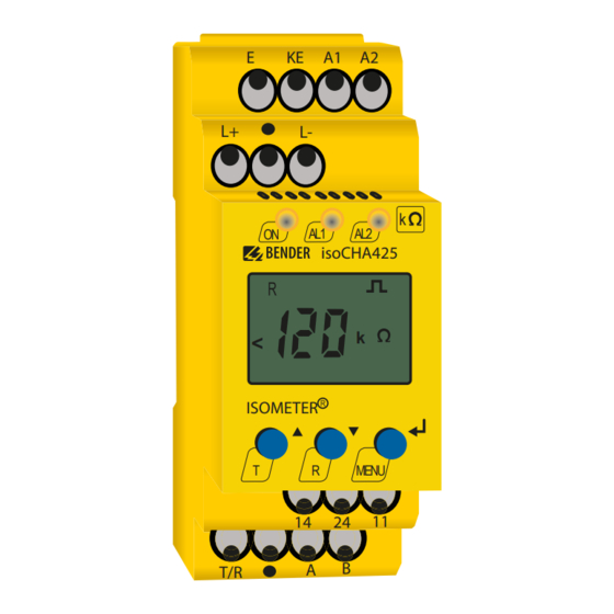
- Page 1 ISOMETER® isoCHA425 Insulation monitoring device for unearthed DC systems (IT systems) DC 50 V up to 400 V Suitable for the charging of electric vehicles acc. to Japanese charging standard CHAdeMO Software version: D0612 V1.xx isoCHA425_D00352_01_M_XXEN / 05.2021 Manual EN...
- Page 2 Service and support for Bender products First-level support Technical support Carl-Benz-Strasse 8 • 35305 Grünberg • Germany Telephone: +49 6401 807-760 0700BenderHelp * Fax: +49 6401 807-629 E-mail: support@bender.de Available on 365 days from 7.00 a.m. to 8.00 p.m. (MEZ/UTC +1) * Landline German Telekom: Mon-Fri from 9.00 a.m.
-
Page 3: Table Of Contents
Indication of important instructions and information ........5 1.2.1 Signs and symbols ......................5 Training courses and seminars.................5 Delivery conditions .......................5 Inspection, transport and storage ................6 Warranty and liability....................6 Disposal of Bender devices ..................6 Safety ..........................7 Function ....................8 Intended use ........................8 Device features ......................8 Functional description ....................9 2.3.1 General measuring functions ...................9... - Page 4 Menu „out“ ........................22 4.4.1 Configuration of the relay operating mode ............. 22 4.4.2 Relay alarm assignment „r1“ and „r2“ and LED assignment ...... 23 4.4.3 Fault memory configuration .................. 24 4.4.4 Interface configuration .................... 24 Menu „t“ ......................... 24 4.5.1 Time configuration ....................
-
Page 5: General Instructions
Training courses and seminars www.bender.de > Know-how-> Seminars. Delivery conditions The conditions of sale and delivery set out by Bender apply. These can be obtained from Bender in printed or electronic format. The following applies to software products: “Software clause in respect of the licensing of standard software as part of de-... -
Page 6: Inspection, Transport And Storage
• Non-observance of technical data. • Repairs carried out incorrectly. • Use of accessories and spare parts not recommended by Bender. • Catastrophes caused by external influences and force majeure. • Mounting and installation with device combinations not recommended by the manufac- turer. -
Page 7: Safety
ISOMETER® isoCHA425 Safety If the device is used outside the Federal Republic of Germany, the applicable local standards and regulations must be complied with. In Europe, the European standard EN 50110 applies. ! Risk of electrocution due to electric shock! anger Touching live parts of the system carries the risk of: •... -
Page 8: Function
• Measured value indication via multi-functional LCD • Fault memory can be activated • RS-485 (galvanically isolated) including the following protocols: – BMS interface (Bender measuring device interface) for data exchange with other Bender components – Modbus RTU – IsoData (for continuous data output) •... -
Page 9: Functional Description
ISOMETER® isoCHA425 Functional description The ISOMETER® measures the insulation resistance R of DC charging stations according to the Japanese charging standard CHAdeMO. 2.3.1 General measuring functions The ISOMETER® measures the RMS value (True RMS) of the nominal system voltage U between L+ and L- as well as the residual voltages U (between L+ and earth) and U... -
Page 10: Function Tests Of Relay In The Charging Station And The Vehicle
Function 2.3.2 Function tests of relay in the charging station and the vehicle If the ISOMETER® is disconnected from the voltage source to be monitored single-pole during a function test of the charging station or vehicle relay, a false alarm can happen depending on the location of an existing insulation fault. - Page 11 ISOMETER® isoCHA425 Error codes If, contrary to expectations, a device error should occur, error codes will appear on the display. Some of these are described below: Error code Description PE connection error The connections „E“ or „KE“ to earth are interrupted. E.01 Action: Check connection, eliminate error.
-
Page 12: Malfunction
LEDs „ON“/“AL1“/“AL2“ will flash. If the error occurs again after restarting the device or after restoring the factory settings, please contact Bender Service. 2.3.8 Signalling assignment of the alarm relays K1/K2 The notifications for „device error“, „insulation fault“, „insulation impedance fault“, „undervoltage/overvoltage fault“, „device test“... -
Page 13: Password Protection (On, Off)
ISOMETER® isoCHA425 Response delay t The response delay t can be set uniformly for all messages in the „t“ menu using the parameter „ton“, whereby each alarm message specified in the alarm assignment has its own timer for t This delay time can be used for interference suppression in the case of short measuring times. An alarm will only be signalled when a threshold value of the respective measuring value is violated for the period of t without interruption. -
Page 14: External, Combined Test Or Reset Button T/R
Function 2.3.12 External, combined test or reset button T/R Reset = Press the external button < 1.5 s Reset followed by a test = Press the external button > 1.5 s Stop measuring function = Press and hold the external button When the measuring function is stopped, the display shows „STP“. -
Page 15: Interface/Protocols
The ISOMETER® uses the serial hardware interface RS-485 with the following protocols: • BMS The BMS protocol is an essential component of the Bender measuring device interface (BMS bus protocol). Data transmission takes place with ASCII characters. • Modbus RTU... -
Page 16: Installation, Connection And Commissioning
Installation, connection and commissioning Installation, connection and commissioning Dimensions Fig. 3–1 All dimensions in mm Mounting Click & Click! Variant A: DIN rail mounting Variant B: Screw mounting The front plate cover can be opened at the lower part marked with an arrow. isoCHA425_D00352_01_M_XXEN / 05.2021... -
Page 17: Wiring Diagram
ISOMETER® isoCHA425 Wiring diagram DC charging station acc. to CHAdeMO E KE Test / Reset MENU COM465IP RS-485 For details about the conductor cross sections required for wiring, refer to the technical data on page Legend Terminal Connections Connection to the supply voltage U via fuse (line protection): A1, A2 If supplied from an IT system, both lines have to be protected by a fuse.*... -
Page 18: Commissioning
Installation, connection and commissioning Commissioning 1. Check that the ISOMETER® is properly connected to the system to be monitored. 2. Connect the supply voltage U to the ISOMETER®. The device carries out a calibration, a self test and adjusts itself to the IT system to be monitored. -
Page 19: Operation Of The Device
ISOMETER® isoCHA425 Operation of the device The menu structure is illustrated schematically on the following pages. After pressing the „MENU“ button for > 1.5 s, the first menu item „AL“ appears. (Enter) buttons for navigation and settings. Up and down button: •... -
Page 20: Display Elements
Operation of the device Display elements Device front/display Function green - on yellow - alarm yellow - alarm Assignment according to table on page 23 Up button Test button ( press > 1.5 s) By pressing and holding the test button, the display elements are indicated. -
Page 21: Menu Overview
ISOMETER® isoCHA425 Menu overview Measurement display Menu selection Parameter selection > > < < 1.5 s 1.5 s > > > > . . . 1.5 s 1.5 s 1.5 s 1.5 s < < t > 5 Min. < < >... -
Page 22: Menu „Al
Operation of the device Menu „AL“ 4.3.1 Response value setting The two parameters that monitor the insulation resistance, „R1“ and „R2“, can be found in the menu „AL“. The value „R1“ can only be set higher than the value „R2“. If the insulation resistance reaches or falls below the activated values „R1“... -
Page 23: Relay Alarm Assignment „R1" And „R2" And Led Assignment
ISOMETER® isoCHA425 4.4.2 Relay alarm assignment „r1“ and „r2“ and LED assignment In the alarm assignment, each alarm is assigned to the respective relay with the setting „on“. The LED indication is directly assigned to the alarms and is not related to the relays. In the event of an unsymmetrical insulation fault, only the alarm corresponding to the assigned conductor (L1/+ or L2/-) will be displayed. -
Page 24: Fault Memory Configuration
Operation of the device 4.4.3 Fault memory configuration Display Description Memory function for alarm messages (fault memory) FAC = Factory setting; Cs = Customer settings 4.4.4 Interface configuration Display Setting value Description Value range BusAdr. Adr = 0 deactivates BMS as well as Modbus and activates isoData 0/3…90 with continuous data output (115k2, 8E1) -
Page 25: Menu „Set
Setting value Description Value range 0…999 Password for parameter setting Monitoring system connection during device test S.Ct Device test during device start Restore factory settings For Bender Service only FAC = Factory setting; Cs = Customer settings isoCHA425_D00352_01_M_XXEN / 05.2021... -
Page 26: Measuring Value Display And History Memory
Operation of the device Measuring value display and history memory Only R or U is permanently shown on the display (standard display). All other measuring value displays switch to the standard display after a maximum of 5 min. The symbol indicates a current measured value. -
Page 27: Data Access Using The Bms Protocol
ISOMETER® isoCHA425 Data access using the BMS protocol The BMS protocol is an essential component of the Bender measuring device interface (BMS bus protocol). ASCII characters are used for the data transfer. BMS channel no. Operation value Alarm Pre-alarm R1... -
Page 28: Data Access Using The Modbus Rtu Protocol
Data access using the Modbus RTU protocol Data access using the Modbus RTU protocol Requests to the ISOMETER® can be made using the function code 0x03 (Read Holding Registers) or the function code 0x10 (Write Multiple Registers). The ISOMETER® generates a function-related answer and sends it back. -
Page 29: Write Modbus Register (Parameter Setting)
ISOMETER® isoCHA425 Write Modbus register (parameter setting) Registers in the device can be modified with the function code 0x10 (Write Multiple Registers). Parameter registers are available from address 3000. The content of the register is listed in the table on page 6.2.1 Command of the Master to the ISOMETER®... -
Page 30: Exception Code
Data access using the Modbus RTU protocol Exception code If a request cannot be answered for whatever reason, the ISOMETER® will send a so-called exception code with which possible faults can be narrowed down. Exception code Description 0x01 Impermissible function 0x02 Impermissible data access 0x03... -
Page 31: Modbus Register Assignment Of The Isometer
ISOMETER® isoCHA425 Modbus register assignment of the ISOMETER® Depending on the device condition, the information in the registers is the measured value without alarm; the measured value with alarm 1; the measured value with alarm 2; or only the device error. Measured value Register Device error... - Page 32 Modbus register assignment of the ISOMETER® Register Property Description Format Unit Value range 3000 Reserved 3001 Reserved 3002 Reserved 3003 Reserved 3004 Reserved Pre-alarm value 3005 resistance measurement UINT 16 kΩ R2…250 „R1“ 3006 Reserved Alarm value resistance 3007 UINT 16 kΩ...
- Page 33 ISOMETER® isoCHA425 Register Property Description Format Unit Value range Start-up delay „t“ during 3018 UINT 16 0…10 device start Response delay „ton“ for 3019 UINT 16 0…99 relays „K1“ and „K2“ Delay on release „toff“ for 3020 UINT 16 0…99 relays „K1“...
-
Page 34: Device-Specific Data Type Of The Isometer
Modbus register assignment of the ISOMETER® Register Property Description Format Unit Value range UNIT 16 (ASCII) - 9800 to 9809 Device name chapter 7.1.1 Software 9820 UINT 16 Software ID Number ID number Software 9821 Software version number UINT 16 version 9822 Software version: Year... - Page 35 ISOMETER® isoCHA425 7.1.2.1 Float = Floating point value of the channels 0x00 0x01 HiByte LoByte HiByte LoByte Presentation of the bit order for processing analogue measuring values according to IEEE 754 S = Sign; E = Exponent; M = Mantissa 7.1.2.2 AT&T = Alarm type and test type (internal/external) 7 6 5 4 3 Meaning...
- Page 36 Modbus register assignment of the ISOMETER® 7.1.2.3 R&U = Range and unit Meaning Invalid (init) No unit Ω Baud °C °F Second Minute Hour Month Actual value The actual value is lower The actual value is higher Invalid value • The units of bits 0 to 4 are coded. •...
-
Page 37: Alarm Assignment Of The Relays
ISOMETER® isoCHA425 7.1.3 Alarm assignment of the relays Several alarms can be assigned to each relay. For the assignment of each relay, a 16-bit-register is used with the bits described below. The following table applies to relay 1 and relay 2, in which „x“ stands for the relay number. -
Page 38: Channel Descriptions
Modbus register assignment of the ISOMETER® Channel descriptions Measuring value description/ Parameter Alarm message Note Operating message 1 (0x01) Insulation fault 71 (0x47) Insulation fault Insulation resistance R in Ω 76 (0x4C) Voltage Measured value in V 77 (0x4D) Undervoltage 78 (0x4E) Overvoltage 82 (0x52) - Page 39 ISOMETER® isoCHA425 To convert parameter data, data type descriptions are required. Text representation is not necessary in this case. Parameter Description of parameters Parameter/measured value invalid. 1023 (0x3FF) The menu item of this parameter is not displayed. 1022 (0x3FE) No measured value/no message 1021 (0x3FD) Measured value/parameter inactive Measured value/parameter only temporarily inactive (e.g.
-
Page 40: Isodata Data String
IsoData data string IsoData data string In IsoData mode, the ISOMETER® continuosly sends the whole data string with a cycle time of approximately 1 s. Communication with the ISOMETER® within this mode is not possible and no additional sender may be connected via the RS-485 bus cable. IsoData is activated in the menu „out“, menu item „Adr“... -
Page 41: Technical Data
ISOMETER® isoCHA425 Technical data Tabular presentation ( )* = factory setting Insulation coordination acc. to IEC 60664-1/IEC 60664-3 Definitions: Measuring circuit (IC1) ................................. L+, L- Supply circuit (IC2) ................................A1, A2 Output circuit (IC3) ................................ 11, 14, 24 Control circuit (IC4) ..............................E, KE, T/R, A, B Rated voltage ...................................... - Page 42 Technical data Response values Response value R ..............................R …250 kΩ (46 kΩ)* Response value R ............................... 5 kΩ…R (23 kΩ)* Relative uncertainty R ............................. ±15 %, at least ±2 kΩ Hysteresis R .................................. 25 %, at least 1 kΩ Undervoltage detection U<...
-
Page 43: Standards, Approvals And Certifications
ISOMETER® isoCHA425 Environment/EMC EMC ......................................IEC 61326-2-4 Ambient temperatures: Operation ....................................-40…+70 ºC Transport ....................................-40…+85 ºC Storage ....................................-40…+70 ºC Climatic class acc. to IEC 60721: Stationary use (IEC 60721-3-3) ..................3K24 (without condensation and formation of ice) Transport (IEC 60721-3-2) ..................... 2K11 (without condensation and formation of ice) Langzeitlagerung (IEC 60721-3-1) ................ -
Page 44: Ordering Information
Technical data Ordering information Type Version Art. No. isoCHA425-D4-4 Push-wire terminal B71036395 Mounting clip for screw fixing B98060008 (1 piece/device) Document revision history Valid from software Date Document version State/Changes version 04.2018 D0162 V1.xx First edition 05.2021 D0162 V1.xx Editorial revision Added: chapter 2.3.12: Note on stopped measuring function... - Page 45 ISOMETER® isoCHA425 isoCHA425_D00352_01_M_XXEN / 05.2021...
- Page 46 Nachdruck und Vervielfältigung Reprinting and duplicating nur mit Genehmigung des Herausgebers. only with permission of the publisher. Bender GmbH & Co. KG Bender GmbH & Co. KG Postfach 1161 • 35301 Grünberg • Deutschland PO Box 1161 • 35301 Gruenberg • Germany Londorfer Str.
Need help?
Do you have a question about the ISOMETER isoCHA425 and is the answer not in the manual?
Questions and answers