Table of Contents
Advertisement
Advertisement
Table of Contents

Related Manuals for Bender ISOMETER iso685-D-P


Summary of Contents for Bender ISOMETER iso685-D-P
- Page 1 Manual ISOMETER® iso685-D-P iso685W-D-P iso685-S-P iso685W-S-P Insulation Monitoring Device with integrated locating current injector for IT AC systems with galvanically connected rectifiers and inverters and for IT DC systems iso685-D-P_D00170_00_M_XXEN/06.2016...
- Page 2 E-Mail: info@bender.de Web: www.bender.de Customer service Service-Hotline: 0700-BenderHelp (Telephone and Fax) Carl-Benz-Straße 8 • 35305 Gruenberg • Germany © Bender GmbH & Co. KG Tel.:+49 6401 807-760 All rights reserved. Fax:+49 6401 807-629 Reproduction only with permission of the publisher.
-
Page 3: Table Of Contents
Table of contents 1. Important information ..............8 4. Device overview ................15 1.1 How to use this manual ..........8 4.1 Dimensions. - Page 4 Table of contents 7. Commissioning ................32 10. Settings................... 44 7.1 General initial commissioning process......32 10.1 Settings in the device menu .
- Page 5 Table of contents 10.1 1.10.3.5 Function 3 ........49 10.1 2.4.4.3 Trigger .
- Page 6 Table of contents 10.1 6.2.2 Format (time)........60 11.
- Page 7 Table of contents 17. Technical data ................81 17.1 Tabular data ........... . . 81 17.2 Option W .
-
Page 8: Important Information
Bender devices WARNING • Extended guarantee for Bender devices, which includes an in-house repair service or replacement devices at no extra cost This signal word indicates a low level risk that can result in minor or... -
Page 9: Field Service
Electronic Manufacturer's Association) also applies. • Batteries and accumulators are not part of household waste and must be disposed Sale and delivery conditions can be obtained from Bender in printed or electronic format. of in accordance with the regulations. 1.5 Inspection, transport and storage •... -
Page 10: Safety Instructions
2.3 Device-specific safety information Part of the device documentation in addition to this manual is the enclosed "Safety in- structions for Bender products". Make sure that the basic settings meet the requirements of the IT system. Children and unauthorised persons must not have access to or contact 2.2 Work activities on electrical installations. -
Page 11: Intended Use
Intended use also implies: (Option; COMTRAXX® gateway) • The observation of all information in the operating manual • Worldwide remote diagnosis via the Internet (made available by Bender Service • Compliance with test intervals only) • RS-485/BS (Bender sensor bus) for communication with other Bender devices In order to meet the requirements of applicable standards, customised parameter set- •... -
Page 12: Features Eds44
Function Function Hereafter, the ISOMETER®s with integrated display are described. This description is sim- 3.1.2 Features EDS44… ilar to the combination of ISOMETER® sensor variants and the front panel FP200. The de- • Insulation fault location in AC, 3AC and DC IT systems vices to which this manual applies will be referred to as ISOMETER®s hereafter. -
Page 13: Insulation Fault Location
• BCOM for Bender device communication via Ethernet • BS bus for communication of Bender devices (RS-485) • BB bus for communication of Bender devices (Bender-internal device bus) • Integrated web server for reading out measured values and for parameter setting... -
Page 14: Self Test
Function Function 3.6 Self test 3.7 Compatibility with EDS After switching on the supply voltage, the ISOMETER automatically and continuously checks all internal measuring functions, the components of the process control such as Device Notes the data and parameter memory, as well as the connections to the IT system and earth. iso685-x-P Additionally, all EDS devices connected to the ISOMETER®... -
Page 15: Device Overview
4. Device overview 4.1 Dimensions 1 0 8 m m 1 1 0 iso685-D-P_D00170_00_M_XXDE/06.2016... -
Page 16: Device Variants
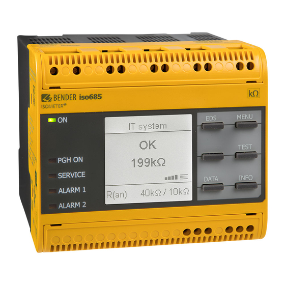
Device overview 4.2 Device variants The device variant ISOMETER® iso685-D-P features a high-resolution graphic LC display and operating controls for direct operation of the device functions. iso685-D-P: It cannot be combined with an FP200. The device variant ISOMETER® iso685-S-P features neither a display nor operating controls. iso685-S-P: It can only be used in combination with the FP200 and it is operated via this front panel. -
Page 17: Connections And Panel
PGH ON PGH ON DATA INFO LEDs: PGH ON, SERVICE, ALARM 1, ALARM 2 Optional expansion module for Bender devices (e. g. BB-Bus) REMOTE interface to connect to the FP200 Bottom Multifunctional I/O interface (refer to page Ethernet interface Switchable terminating resistor for termination... -
Page 18: Display Elements And Device Buttons
Device overview Device overview 4.4 Display elements and device buttons Device buttons You can adjust the device settings in the respective menu using the menu buttons. Depending on the menu entry, one of the options displayed below is assigned to the buttons. -
Page 19: Mounting
Mounting 5. Mounting 5.1 General instructions 5.2 Screw mounting 19. Fix the three mounting clips delivered with the device (two of them packed sepa- rately) manually or using a tool, as illustrated below. Only qualified personnel are permitted to carry out the work necessary 20. -
Page 20: Din Rail Mounting
Connection 6. Connection 6.1 Connection requirements 5.3 DIN rail mounting Consider the minimum distance to adjacent devices: 1. Fix the three mounting clips delivered with the device (two of them packed sepa- lateral 0 mm, top 20 mm, bottom 20 mm. rately) manually or using a tool, as illustrated below. - Page 21 Connection Connection Prevent measurement errors! Provide line protection! When an AC system being monitored contains galvanically coupled DC According to DIN VDE 0100-430, a line protection shall be provided for the circuits, take into consideration that: an insulation fault can only be de- supply voltage.
-
Page 22: Connection To A 3(N)Ac System
Connection Connection 6.2 Connection to a 3(N)AC system 6.3 Connection to an AC system Risk of injury, fire and damage to property due to a short circuit! Risk of injury, fire and damage to property due to a short circuit! According to DIN VDE 0100-430, devices used to protect against a short According to DIN VDE 0100-430, devices used to protect against a short circuit when terminals L1/+, L2 und L3/- are coupled to the IT system to be... -
Page 23: Connection To A Dc System
Connection Connection 6.4 Connection to a DC system 6.5 Connection to the X1 interface Risk of injury, fire and damage to property due to a short circuit! According to DIN VDE 0100-430, devices used to protect against a short circuit when terminals L1/+, L2 und L3/- are coupled to the IT system to be monitored can be omitted if the wiring is carried out in such a manner as WARNING to reduce the risk of a short circuit to a minimum. -
Page 24: Connection To The Supply Voltage
Connection Connection 6.6 Connection to the supply voltage 6.7 Connection to the Ethernet interface Danger of damage to property due to faulty connections! The device can be damaged if the unit is simultaneously connected to the supply voltage via the X1 interface, and A1/+ and A2/- terminals. Do not connect the device simultaneously via X1, and A1/+ and A2/- to different CAUTION supply voltages. -
Page 25: Connection To The Relay 1 Interface (11 12 14)
Connection Connection 6.8 Connection to the relay 1 interface (11 12 14) 6.9 Connection to the relay 2 interface (21 22 24) Relais 1 Relais 2 Gemeinsamer Kontakt Gemeinsamer Kontakt Schließer Öffne Schließer Position the terminal cover and click it into place Position the terminal cover and click it into place iso685-D-P_D00170_00_M_XXDE/06.2016... -
Page 26: Connection To The Bb Bus
6.10 Connection to the BB bus 6.11 Connecting the EDS to the ISOMETER® The BB bus is an interface that enables Bender devices to communicate with each other. The BB bus can be used with an ISOMETER® and one or more EDS44…-S. For this purpose,... -
Page 27: Connection Example Isometer® To Eds
Connection 6.11.1 Connection example ISOMETER® to EDS to the loads to the loads to the loads to the loads A1/+ A2/- L1/+ L3/- KE E A1/+ A2/- EDS440 EDS440 EDS440 ISOSCAN® ISOSCAN® ISOSCAN® IT-System TEST CHANNELS RESET PGH ON >20 MΩ >20 MΩ... -
Page 28: Connection To A 3(N)Ac System
Connection 6.11.2 Connection to a 3(N)AC system to the loads to the loads A1/+ A2/- L1/+ L3/- KE E A1 A2 A1/+ A2/- 11 12 EDS440 EDS440 ISOSCAN® ISOSCAN® IT-System TEST CHANNELS RESET PGH ON >20 MΩ >20 MΩ SERVICE ALARM SLAVE ADDRESS ∆... -
Page 29: Connection To An Ac System
Connection 6.11.3 Connection to an AC system to the loads to the loads A1/+ A2/- L1/+ L3/- KE E A1 A2 A1/+ A2/- 11 12 EDS440 EDS440 ISOSCAN® ISOSCAN® IT-System TEST CHANNELS RESET PGH ON >20 MΩ >20 MΩ SERVICE SLAVE ADDRESS ALARM ∆... -
Page 30: Connection To A Dc System
Connection 6.11.4 Connection to a DC system to the loads to the loads A1/+ A2/- L1/+ L3/- KE E A1 A2 A1/+ A2/- 11 12 EDS440 EDS440 ISOSCAN® ISOSCAN® IT-System TEST CHANNELS RESET PGH ON >20 MΩ >20 MΩ SERVICE ALARM SLAVE ADDRESS ∆... -
Page 31: System Structure
Connection 6.11.5 System structure The application example below shows the monitoring of a control system with the ISOMETER® iso685-D-P and the EDS441-S. AC 24 V DC 110 V Input Output A1/+ A2/- L1/+ L3/- KE E EDS440 EDS441 ISOSCAN® ISOSCAN® IT-System PGH ON >20 MΩ... -
Page 32: Commissioning
Commissioning 7. Commissioning 7.1 General initial commissioning process Commissioning flow chart 1. Check that the ISOMETER® is properly connected to the system to be monitored. ® Commissioning the ISOMETER Commissioning the EDS44… System commissioning of 2. Connect the supply voltage to the ISOMETER®. Adjust the device using the commis- ®... -
Page 33: Initial Commissioning
Commissioning Commissioning 7.2 Initial commissioning 7.2.3 Setting system type By setting the system type the insulation monitoring device can be optimally adapted to the system to be monitored. The system type is essential information for the insulation monitoring device in order to determine the insulation resistance correctly. Check network function! When the device has been integrated into a network, the influence on the System type... -
Page 34: Setting Eds Current
Commissioning Commissioning 7.2.6 Setting EDS current 7.3 Recommissioning Set the maximum locating current. If the device has already been put into operation once, the self test will be carried out EDS441: 1-5 mA shortly after connecting the supply voltage. The commissioning wizard will not restart. EDS440: 10-50 mA You can restart the commissioning wizard using the following menu path: For further information, refer to... -
Page 35: Commissioning Eds
Commissioning Commissioning 7.4 Commissioning EDS Proceed as follows to put into operation an EDS after commissioning the ISOMETER®: 1. First, search for all available measuring channels. Menu path: Menu/EDS/Scan channels. Channel Scanning channels 2.2 √ BB-Bus Search for EDS channels? BS-Bus Cancel Start... -
Page 36: Display
Display 8. Display 8.1 Standard display 8.2 Fault display (active) During normal operation, the ISOMETER® displays the message OK and below, the cur- An active fault is displayed by . The upper part of the display will become orange and rently measured insulation resistance. -
Page 37: Fault Display (Inactive)
Display Display If several fault messages have appeared, you can navigate through the faults using the 8.3 Fault display (inactive) buttons. In addition to the type of fault and the associated alarm value, you can An inactive fault is displayed by . -
Page 38: Acknowledging A Fault Message
Display Display 8.4 Acknowledging a fault message 8.5 Data - isoGraph In order to acknowledge the fault message and return to the ISOMETER®'s standard dis- The isoGraph represents the chronological sequence of the insulation resistance over play, all faults must be acknowledged by means of the reset button. time. -
Page 39: History Memory
Display Display 8.6 History memory 8.7 Insulation fault location Up to 1023 alarm messages and device errors are stored in the history memory with date When EDS mode is activated, the ISOMETER® indicates the message "Ins. fault locat.". Be- and time stamp. When the history memory is deleted, the minimum insulation resistance low, on the left side it indicates which EDS mode is activated. -
Page 40: Initial Measurement
Display Display Insulation fault location in auto mode and 1 cycle. 8.8 Initial measurement During the initial measurement, the device records all measured values. All measured values that may have been recorded before will be discarded if a new initial measurement is started. -
Page 41: Menu
Menu 9. Menu 9.1 Menu structure 2. EDS 1. General 1. Alarm settings 1. Current 1. Insulation Alarm 2. Mode 1. Alarm 1 2. Use portable EDS 2. Alarm 2 2. Scan for channels 3. Memory 3. Enable channel 4. Group settings 2. -
Page 42: Operating And Navigating
Menu Menu 9.2 Operating and navigating 3. Data measured values Navigate through the device menu using the device buttons. The functions of the device 4. Control buttons are described in the chapter “Display elements and device buttons” on page 5. History 6. -
Page 43: Multiple Selection In The Device Menu
Menu Menu 9.2.2 Multiple selection in the device menu At some points in the menu, you can select several channels, relays, etc. at a time. There- by, you can make settings for several selection points simultaneously. Select 1…n selection points using the buttons. -
Page 44: Settings
Settings 10. Settings 10.1 Settings in the device menu 10.1 1.1.3 Fault memory Automatic reset of inactive faults at the outputs relay 1, relay 2, digital output 1, digital The settings of the ISOMETER® are explained in the order of the device menu. output 2: 10.1 1.0 Alarm settings... -
Page 45: Profile
Settings Settings 10.1 Profile 10.1 1.5.1 ISOnet Adapt the area of application of the ISOMETER® to your system profile. For a description Activate or deactivate the ISONet function of the profiles, refer to “Device profiles” on page The following can be selected: The ISOnet is deactivated •off The ISOnet function is activated via BCOM... -
Page 46: Inputs
Settings Settings 10.1 Inputs The ISOMETER® provides a total of three digital inputs. An event is carried out on the falling edge of the •Active low The exemplary wiring diagram shows how the digital inputs can be wired: digital input (high to low). Response time t(on)/t(off ) after a switch-off sig- nal. -
Page 47: Function
Settings Settings 10.1 1.9.1.4 Function 10.1 1.10 Outputs The parameters for the function of the digital inputs of the ISOMETER® can be set differ- The ISOMETER® provides a total of six outputs. ently: The following parameters can be set for the outputs: 10.1 1.10.1 Relay 1 Digital input without function... -
Page 48: Function 3
Settings Settings Select the appropriate setting for function 1. The following parameters can be set. The status of the output changes on the occurrence of any •Common alarm alarm and fault messages The function is not used. •off (Ins. alarm 1 & 2, DC- / DC+ alarm, symmetrical alarm, con- nection and device faults). -
Page 49: Test
Settings Settings 10.1 1.10.3.1 TEST 10.1 1.10.4 Digital 2 The functional test of the digital output can be activated or deactivated. This only applies Refer to “10.1 1.10.3 Digital 1”. to the manual test and not to the cyclic device self test: 10.1 1.10.5 Buzzer The following parameters can be set for the buzzer:... - Page 50 Settings Settings 10.1 1.10.6 Analogue 10.1 1.10.6.2 Midscale The following parameters can be set for the analogue output: Select the appropriate midscale. The following parameters can be set: 10.1 1.10.6.1 Mode The switching signal is linear to the insulation resistance in •Linear The following values can be set for the operating mode of the analogue output the indicated measuring range.
- Page 51 Settings Settings 10.1 1.10.6.3 TEST 10.1 2.0 EDS (insulation fault location) The functional test of the analogue output can be activated or deactivated. In this way, 10.1 General the analogue output is adjusted once for the entire range. This only applies to the manual test and not to the cyclic device self test: 10.1 2.1.1...
- Page 52 Settings Settings 10.1 2.1.2 Mode To locate insulation faults, select one of the three available modes for insulation fault location. Do not carry out a manual test during a manually started insulation fault location, since the insulation fault location would be aborted by that. In manual mode, the insulation fault location does not start •Manual automatically.
- Page 53 Settings Settings 10.1 Activating channels 10.1 2.4.1 Channel During initial commissioning all channels are inactive. Before configuring the channels Before configuring a measuring channel, you must activate it. they must be activated in this menu. Select which measuring channel you would like to activate and configure. Select which measuring channels you would like to activate.
- Page 54 Settings Settings 10.1 2.4.1.3 Response value 10.1 2.4.2.1 Relays ΔL Set the response value for I (main alarm for insulation fault location) between 200 µA Select the relays that you would like to configure. ∆L and 10 mA. The response value must be below the set locating current (refer to 7.2.6 “Setting EDS current”...
- Page 55 Settings Settings 10.1 2.4.2.1.3 Function 1 10.1 2.4.2.2 Buzzer Up to three functions can be assigned to one output. The functions are linked to an OR Select the buzzers that you would like to configure. operator: All buzzers are selected. Function 1 •Select all No buzzer is selected.
- Page 56 Settings Settings 10.1 2.4.2.3.1 TEST 10.1 2.4.3.1 Mode The functional test of the digital output can be activated or deactivated. This only applies The operating mode for the digital input can be set to the following values. For a descrip- to the manual test and not to the cyclic device self test: tion of the operating modes, refer to “Mode”...
- Page 57 Settings Settings 10.1 2.4.4.1 System type 10.1 2.4.4.3 Trigger The locating current pulse of the ISOMETER® is synchronised with the measurement tech- nology in the EDS via the BB bus or the BS bus. This allows a more reliable detection of the Settings made to this menu point will only have an effect on connected locating current pulse in the event of disturbances.
- Page 58 Settings Settings 10.1 2.5.2 Current transformer monitoring 10.1 2.6.2.3 Function 2 Refer to “10.1 2.4.1.2 CT monitoring”. Refer to “10.1 2.4.2.1.3 Function 1”. 10.1 2.5.3 Response value I 10.1 2.6.2.4 Function 3 ΔL Refer to “10.1 2.4.1.3 I∆L Response value”. Refer to “10.1 2.4.2.1.3 Function 1”.
- Page 59 Reset of fault and alarm messages •RESET 10.1 Service All recorded measurements are discarded and a The service menu can only be accessed by Bender Service staff. •Start initial measure- new measurement is started ment 10.1 3.0 Data measured values Starting and stopping the insulation fault loca- The ISOMETER®...
-
Page 60: Format (Time)
Settings Settings 10.1 Clock 10.1 6.2.4 Date In the clock menu you can set the display format of time and date for the ISOMETER® Based on the selected date format you can set the current date. iso685: 10.1 6.2.5 Format (date) Select the appropriate date format you want to be displayed: 10.1 6.2.1... -
Page 61: Write Access
Settings Settings 10.1 6.3.1 Write access 10.1 6.3.3 BCOM Set whether the device can be parameterised externally via Modbus or web server. Dis- Set the parameters for communication with other devices via BCOM. playing and reading out data via Modbus and web server is always possible, regardless of For further information, refer to “BCOM”... -
Page 62: Port 502
•Save The ISOMETER® restores your initial device set- •Restore 10.1 6.3.5 BS bus tings. Set the parameters for communication with other devices via the Bender sensor bus. For further information, refer to “BS bus” on page 10.1 Service 10.1 6.3.5.1 Address The service menu can only be accessed by Bender Service staff. -
Page 63: Factory Settings
Settings Settings 10.2 Factory settings Parameter Value Parameter Value Interfaces Response values/alarms DHCP Response value R (ALARM 1) 40 kΩ IP address 192.168.0.5 Response value R (ALARM 2) 10 kΩ Net mask 255.255.255.0 DC alarm BCOM address system-1-0 DC-offset voltage for DC alarm 65 V Device address BS bus Fault memory... -
Page 64: Device Communication
Data can be read out with a read command on the register address. With a write com- mand, data can be written into a register address. BCOM is intended for communication between Bender devices via Ethernet. The register addresses of the individual measured values und parameters can be found All devices that communicate via BCOM must have the same system name. -
Page 65: Web Server
• Easy and fast parameter setting of the device and the connected EDS. • Easy assignment and edition options of device and measuring channel texts. • Maintenance • Data storage of specific events for fast support by Bender Service. Legend for web server device menu (first level) START Indication of general device information. - Page 66 Device communication Web server user interface iso685-D-P_D00170_00_M_XXDE/06.2016...
- Page 67 Device communication Device communication Legend for user interface Main menu of the web server (first level) • START (1) • DEVICE (2) • ALARMS (3) • PARAMETER ADDRESSES (4) Refer to “Web server device menu (first level)” on page ISOMETER® and EDS settings. Menu Adjust device settings here.
-
Page 68: Bs Bus
The RS-485 specification restricts the cable length to 1200 m and requires a daisy chain The BS bus is used to extend Bender measuring devices (e.g. ISOMETER®) with Bender sen- connection. The number of devices on the BS bus is only limited by the BS bus master. -
Page 69: Insulation Fault Location
Insulation fault location 12. Insulation fault location 12.1 General description 12.4 Starting and stopping the insulation fault location An additional function of the ISOMETER® in combination with the EDS is the selective in- The insulation fault location can be started and stopped via different interfaces: sulation fault location. -
Page 70: Special Functions For Coupled It Systems
Special functions for coupled IT systems 13. Special functions for coupled IT systems 13.1 Particularities when monitoring coupled IT systems When using ISOMETER®s in IT systems, make sure that only one active ISOMETER® is con- IT-System 1 IT-System 2 nected in each interconnected system. If several ISOMETER®s are to be connected to the IT system, ensure that only one ISOMETER®... -
Page 71: System Isolation Via Isonet
Special functions for coupled IT systems Special functions for coupled IT systems 13.3 System isolation via ISOnet The ISOnet function ensures via an Ethernet connection that only one ISOMETER® of the Maximum number of devices in an ISOnet interconnection: 20 devices interconnection is active when several ISOMETER®s are connected to an IT system. - Page 72 Special functions for coupled IT systems Special functions for coupled IT systems For the ISOnet function, the following settings are made in the menu: Alarm settings -> ISONet -> ISONet = BCOM. The ISOnet function of all ISOMETER®s existing in the system has to be activated and the number of devices has to be determined.
-
Page 73: Device Profiles
14. Device profiles Adjustment to different applications can be carried out very easily by selecting a device profile. System Nominal system Mains Measuring leakage Description voltage frequency voltage capacitance Main circuits without dynamic frequency changes. AC 0…690 V/ The universal profile is suitable for all systems primarily with constant mains fre- Power circuits µF 15…460 Hz... -
Page 74: Diagrams
15. Diagrams 15.1 Response time profile power circuits Response time as a function of the response value (R ) and system leakage capacitance (C ) according to IEC 61557-8 (U = AC 690 V, f = 50 Hz) ≤ 150 µF ≤... -
Page 75: Response Time Profile Generator
Diagrams 15.3 Response time profile generator Response time as a function of the response value (R ) and system leakage capacitance (C ) according to IEC 61557-8 (U = AC 690 V, f = 50 Hz) ≤ 5 µF ≤ 1 µF 1000 10000 Response value R... -
Page 76: Response Time Profile Inverter > 10 Hz
Diagrams 15.5 Response time profile inverter > 10 Hz Response time as a function of the response value (R ) and system leakage capacitance (C ) according to IEC 61557-8 (U = AC 690 V, f = 50 Hz) ≤ 20 µF ≤... -
Page 77: Relative Uncertainty
Diagrams 15.7 Relative uncertainty ≤ 1000 µF ≤ 1 µF iso685-D-P_D00170_00_M_XXDE/06.2016... -
Page 78: Alarm Messages
• Press the test button page 20 mode Service mode active! The device is in maintenance condition • Contact Bender Service SERVICE lights up • Check measured system capacitance or mains frequency in the “Device profiles” on The profile does not suit... - Page 79 “Setting EDS cur- Overtemperature PGH heated up. The ISOMETER® stops the locating current • Contact Bender Service if the fault does not disappear or occurs rent” on page 34 injector until it cools down and then restarts it. more frequently “DC alarm”...
-
Page 80: Alarm Messages Of The Eds
Alarm messages 16.2 Alarm messages of the EDS Alarm message Description Measures Reference LED indicators Interferences during insulation fault location Insulation fault location Possible causes: • Identify interference sources and eliminate them disturbed! • Low-frequency residual currents • External magnetic fields If an insulation fault is located, the message Insulation fault 5 mA appears on the display. -
Page 81: Technical Data
Technical data 17. Technical data 17.1 Tabular data IT system being monitored Nominal system voltage range U ............................. AC 0…690 V Insulation coordination according to IEC 60664-1/IEC 60664-3 ......................................DC 0…1000 V Definitions: Tolerance of U ..................................AC/DC +15 % Measuring circuit (IC1).............................(L1/+, L2, L3/-) Frequency range of U ...............................DC, 1…460 Hz Supply circuit (IC2)................................... - Page 82 Technical data Technical data Display IP address.................................DHCP/manual 192.168.0.5 Indication........................graphic display 127 x 127 pixels, 40 x 40 mm Network mask..................................255.255.255.0 Display range measured value............................0.1 kΩ…20 MΩ BCOM address...................................system-1-0 Function ................................communication interface LEDs ISOnet: ON (operation LED) ....................................green Number ISOnet devices ..................................≤ 20 SERVICE......................................
-
Page 83: Option W
Technical data Technical data Transport (IEC 60721-3-2) .................................. 2K3 DIN rail mounting acc. to................................IEC 60715 Long-term storage (IEC 60721-3-1) ..............................1K4 Screw fixing..............................3 x M4 with mounting clip Classification of mechanical conditions acc. to IEC 60721: Enclosure material ................................polycarbonate Stationary use (IEC 60721-3-3)................................3M4 Flammability class ....................................V-0 Transport (IEC 60721-3-2)...................................2M2... -
Page 84: Standards And Certifications
Technical data Technical data 17.3 Standards and certifications Insulation fault locators The ISOMETER® has been developed in compliance with the following standards: Supply voltage U Type Response value Art. no. • DIN EN 61557-8 (VDE 0413-8) • IEC 61557-8 EDS440-S-1 AC/DC 24…240V 2…10mA B 9108 0201... - Page 85 Technical data Technical data Accessories Art. No. Description iso685 mechanical accessories comprising: B91067903 terminal cover and 2 mounting clips* iso685 plug kit, screw terminals* B91067901 iso685 plug kit, with push-wire terminals B91067902 Front cover 144x72 transparent (for IP65) B 98060005 BB bus 6TE connector B98110001 * included in the scope of delivery...
-
Page 86: Glossary
18. Glossary The BB bus is an interface which enables Bender devices to communicate with each other (Bender-internal device bus). • BB bus The BB bus can be used with an ISOMETER® and one or more EDS44…-S. • BCOM Protocol for communication between Bender devices via an IP-based network. -
Page 87: Index
Index Index Connection requirements 20 Accessories 85 Connectors 17 Alarm DC system 23 Alarm 1 13 Ethernet interface 24 Alarm 2 13 Relay 1 interface (11 12 14) 25 Reset alarm message 59 Relay 2 interface (21 22 24) 25 Settings 44 Supply voltage 24 X1 interface 23... - Page 88 Index Index BCOM 61, 64 EDS 86 BS bus 68 Device settings 56 Ethernet 61, 64 Inputs 56 Modbus TCP 61 Outputs 54 Modbus/TCP 64 Ethernet interface 24 Web server 65 X1 23 ISOnet 71, 86 Function description Insulation fault location 13 ISOMETER 11, 12 LEDs 18 ISOnet 71...
- Page 89 Index Index Normal operation 36 Safety instructions 8 Self test 14 Operating controls 18 Service menu 59, 62 Operating mode 46 Set language 33, 59 Operation Set system type of the system to be monitored 33 Commissioning 21, 32 Setting the time 33, 60 Commissioning EDS 35 Settings 44 Option W 83...
- Page 90 Bender GmbH & Co. KG Customer service Postbox 1161 • 35301 Gruenberg • Germany Service hotline: 0700-BenderHelp (Telephone und Fax) Londorfer Straße 65 • 35305 Gruenberg • Germany Carl-Benz-Straße 8 • 35305 Gruenberg • Germany Tel.: +49 6401 807-0 Tel.:...
Need help?
Do you have a question about the ISOMETER iso685-D-P and is the answer not in the manual?
Questions and answers