Bender ISOMETER isoCHA425 Manual
Insulation monitoring device
Hide thumbs
Also See for ISOMETER isoCHA425:
- Manual (32 pages) ,
- Manual (46 pages) ,
- Quick start manual (13 pages)

Related Manuals for Bender ISOMETER isoCHA425


Summary of Contents for Bender ISOMETER isoCHA425
- Page 1 Manual EN ISOMETER® isoCHA425 Insulation monitoring device For unearthed DC systems 0 V to 400 V Suitable for DC charging stations according to CCS or CHAdeMO Software version: D0612 V4.xx isoCHA425_D00352_03_M_XXEN/08.2023...
- Page 2 isoCHA425_D00352_03_M_XXEN/08.2023...
-
Page 3: Table Of Contents
Indication of important instructions and information...............5 Signs and symbols............................5 Service and Support............................5 Training courses and seminars........................5 Delivery conditions............................6 Inspection, transport and storage......................6 Warranty and liability.............................6 Disposal of Bender devices..........................6 1.10 Safety..................................7 Function.......................8 Intended use..............................8 Device features..............................8 Functional description........................... 9 2.3.1... - Page 4 Table of contents Installation................................16 Connection...............................16 Commissioning...............................18 Operation......................19 Operating and display elements......................19 Menu overview...............................21 Displaying measured values........................22 Setting the response values (AL)......................23 4.4.1 Response values overview.........................23 4.4.2 Setting the insulation resistance parameters..................23 4.4.3 Setting parameters for undervoltage and overvoltage..............23 Configuring fault memory, alarm relays, and interfaces (out)............24 4.5.1 Configuring the relays..........................24...
-
Page 5: General Information
Recycling RoHS directives Service and Support Information and contact details about customer service, repair service or field service for Bender devices are available on the following website: Fast assistance | Bender GmbH & Co. KG. Training courses and seminars Regular face-to-face or online seminars for customers and other interested parties: www.bender.de >... -
Page 6: Delivery Conditions
General information Delivery conditions The conditions of sale and delivery set out by Bender GmbH & Co. KG apply. These can be obtained in printed or electronic format. The following applies to software products: ‘Software clause in respect of the licensing of standard software as part of deliveries,... -
Page 7: Safety
ISOMETER® isoCHA425 1.10 Safety If the device is used outside the Federal Republic of Germany, the applicable local standards and regulations must be complied with. In Europe, the European standard EN 50110 applies. DANGER Risk of fatal injury due to electric shock! Touching live parts of the system carries the risk of: •... -
Page 8: Function
Function Function Intended use The ISOMETER® monitors the insulation resistance R for DC fast charging stations according to CHAdeMO standard or according to Combined Charging System (CCS) for nominal system voltage ranges between DC 0 V and 400 V. In order to meet the requirements of the applicable standards, customised parameter settings must be made on the equipment in order to adapt it to local equipment and operating conditions. -
Page 9: Functional Description
ISOMETER® isoCHA425 – BMS (Bender measuring device interface) for the data exchange with other Bender devices – Modbus RTU – IsoData (for continuous data output) • Password protection against unauthorised changing of parameters • Stop mode to disable the measuring pulse generator Functional description The ISOMETER®... -
Page 10: And C In 'Dc' Mode (Ccs)
Function is the two-pole total insulation fault. It is determined up to a maximum of 2 M . The response time of the one-pole insulation fault R is one second for R ≤ 100 k and U ≥ 50 V. For values >... -
Page 11: Monitoring The Insulation Resistance
ISOMETER® isoCHA425 2.3.7 Monitoring the insulation resistance The insulation resistance R is monitored by means of the parameters 'R1' (prewarning) and 'R2' (alarm) (see chapter 4.4). The value 'R1' can only be set higher than the value 'R2'. If the insulation resistance R reaches or falls below the activated values 'R1' or 'R2', an alarm message is triggered. - Page 12 Function User-controlled test functions The user-controlled test functions interrupt the measuring function of the device. They always include a test of the measurement technology (error code 'E.05') and additionally a test of the connection between the terminals L+ and L– via the system to be monitored (error code 'E.02') which can be activated by the user (menu 'SEt' / 'nEt').
-
Page 13: Alarm Assignment Of The Alarm Relays K1/K2
ISOMETER® isoCHA425 Error code Meaning Measurement error Due to system interferences or a device error, the insulation measured value is no longer updated. Prewarning and alarm are set for the insulation measured value at the same time. E.05 Calibration invalid after software update 'E.05' appears together with 'E.08': The software is not compatible to the calibration of the device. -
Page 14: 2.3.13 Digital Interfaces
The ISOMETER® uses the serial hardware interface RS-485 with the following protocols: • BMS The BMS protocol is an essential component of the Bender measuring device interface (BMS bus protocol). Data transmission generally makes use of ASCII characters. • Modbus RTU Modbus RTU is an application layer messaging protocol, and it provides master/slave communication between devices that are connected via bus systems and networks. -
Page 15: Password Protection (On, Off)
ISOMETER® isoCHA425 The delay on release t can be set uniformly for all alarm messages using the parameter 'toff', while each alarm message specified in the alarm assignment has its own timer for t An alarm message will be signalled until the limit value of the respective measured value is no longer violated (including hysteresis) for the duration of t without interruption. -
Page 16: Installation, Connection And Commissioning
Installation, connection and commissioning Installation, connection and commissioning Dimensions 45 70.5 31.1 47.5 74.5 Figure: Dimension diagram (in mm) Installation Figure: DIN rail mounting (left) or screw mounting (right) Connection DANGER Risk of fatal injury due to electric shock! Touching live parts of the system carries the risk of: •... - Page 17 ISOMETER® isoCHA425 Wiring diagram E KE Test / Reset MENU COM465IP RS-485 Figure: Wiring diagram Legend to wiring diagram Terminal Connections A1, A2 Connection to the supply voltage U via fuse (line protection): If supplied from an IT system, protect both lines by a fuse.* E, KE Connect each terminal separately to PE: Use same wire cross section as for 'A1', 'A2'.
-
Page 18: Commissioning
Installation, connection and commissioning * For UL applications: Use 60/70 °C copper lines only! For UL and CSA applications, using 5 A fuses for the protection of the supply voltage U is mandatory. Commissioning Check that the ISOMETER® is properly connected to the system to be monitored. Connect supply voltage U to the ISOMETER®. -
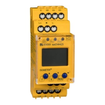
Page 19: Operation
ISOMETER® isoCHA425 Operation Operating and display elements Device front Operating elements Function Device is running Prewarning Overvoltage Alarm Undervoltage Up and down buttons – For navigating up or down in the menu settings. – For increasing or decreasing values. Test button (press > 1.5 s) Reset button (press >... - Page 20 Operation Display Display elements Function Nominal system voltage U Insulation resistance R System leakage capacitance C Monitored conductors L1 L2 L1 = L+ L2 = L– Voltage type DC Pulse symbol: error-free measured value update Voltage type AC auto Automatic self test active °C Measured values and units μ...
-
Page 21: Menu Overview
ISOMETER® isoCHA425 Menu overview Measurement display Menu selection Parameter selection Menu item Parameter Querying and setting response values Configuring fault memory, alarm relays and interface Setting delay times and self test cycles Setting device control parameters Querying software version Querying and clearing the history memory Going to the next-higher menu level isoCHA425_D00352_03_M_XXEN/08.2023... -
Page 22: Displaying Measured Values
Operation Displaying measured values Overview Display Description Insulation resistance 1 k … 2 M Resolution: 1 k ; from 1 M : 0.1 M ✓ ± R k The '+' or '–' sign appears, when an error of R < 100 k is mainly detected at L+ or L–... -
Page 23: Setting The Response Values (Al)
ISOMETER® isoCHA425 Changing the standard display or U can be set as standard display: From the standard display, navigate to the desired display with the up or down button. Confirm with Enter. Setting the response values (AL) 4.4.1 Response values overview Display Activation Setting value... -
Page 24: Configuring Fault Memory, Alarm Relays, And Interfaces (Out)
Operation Configuring fault memory, alarm relays, and interfaces (out) Call up menu 'out' to configure fault memory, alarm relays, and interfaces. 4.5.1 Configuring the relays Relay K1 Relay K2 Description Display Display Operating n.c. n.c. mode of the relay n.c./n.o. FAC Factory settings Customer settings 4.5.2... -
Page 25: Activating Or Deactivating Fault Memory
ISOMETER® isoCHA425 K1 'r1' K2 'r2' LEDs Description Display Display Device start with alarm S.AL S.AL FAC Factory settings Customer settings LED off LED flashes LED on 4.5.3 Activating or deactivating fault memory Display Description Memory function for alarm messages (fault memory) FAC Factory settings Customer settings 4.5.4... -
Page 26: Setting Delay Times And Self Test Cycles (T)
≤ 1 s if R ≤ 100 k ≤ 10 s if R > 100 k and R System connection test S.Ct Device test at device start Restore factory settings For Bender Service only FAC Factory settings Customer settings isoCHA425_D00352_03_M_XXEN/08.2023... -
Page 27: Reset To Factory Settings
ISOMETER® isoCHA425 Reset to factory settings All settings with the exception of the interface parameters are reset to the factory settings. Press MENU button (> 1.5 s). Go to 'SEt' and confirm with Enter. Go to 'FAC' and confirm with Enter. Showing and deleting the history memory ADVICE The history memory saves the measured values for the first fault only. -
Page 28: Data Access Via Rs-485 Interface
Data access via RS-485 interface Data access via RS-485 interface Data access using the BMS protocol The BMS protocol is an essential component of the Bender measuring device interface (BMS bus protocol). Data transmission generally makes use of ASCII characters. BMS channel no. -
Page 29: Writing The Modbus Register (Parameter Setting)
ISOMETER® isoCHA425 Command of the master to the ISOMETER® In the following example, the master of the ISOMETER® requests the content of register 1003 using address 3. The register contains the channel description of measuring channel 1. Byte Name Example Byte 0 ISOMETER®... -
Page 30: Exception Code
Data access via RS-485 interface Response of the ISOMETER® to the master Byte Name Example Byte 0 ISOMETER® Modbus address 0x03 Byte 1 Function code 0x10 Byte 2, 3 Start register 0x0BBB Byte 4, 5 Number of registers 0x0001 Byte 6, 7 CRC16 checksum 0x722A 5.2.3... -
Page 31: Modbus Register Assignment
ISOMETER® isoCHA425 Modbus register assignment 5.3.1 Modbus measured value registers Depending on the device condition, the information in the registers is the measured value without alarm, the measured value with alarm 1, the measured value with alarm 2, or the device error. For more information see , page 32. - Page 32 Data access via RS-485 interface 5.3.1.2 Float = Floating point value of the channels Representation of the bit order for processing analogue measured values according to IEEE 754 Word 0x00 0x01 Byte HiByte LoByte HiByte LoByte 31 30 29 28 27 26 25 24 23 22 21 20 19 18 17 16 15 14 13 12 11 10 exponent mantissa sign...
- Page 33 ISOMETER® isoCHA425 5.3.1.4 R&U = Range and unit Meaning Unit Invalid (init) No unit Baud °C °F Second Minute Hour Month Range of validity Actual value The actual value is lower The actual value is higher Invalid value • Bits 0 to 4: coding for the unit •...
-
Page 34: Modbus Parameter Register
Data access via RS-485 interface 5.3.1.5 Channel descriptions Value Description of measured value / message Comments 1 (0x01) Insulation fault 71 (0x47) Insulation fault Insulation resistance R 76 (0x4C) Voltage Measured value in V 77 (0x4D) Undervoltage 78 (0x4E) Overvoltage 82 (0x52) Capacitance Measured value in F... - Page 35 ISOMETER® isoCHA425 Register Property Description Format Unit Value range Activation alarm value overvoltage 'U >' 0 = off 3010 UINT 16 1 = on 3011 Alarm value overvoltage 'U >' UINT 16 U < … 500 Memory function for alarm 0 = off 3012 UINT 16...
- Page 36 Data access via RS-485 interface Register Property Description Format Unit Value range 0 = Stop 3026 Request stop mode (0 = deactivate device) UINT 16 1 = --- 3027 Alarm assignment of relay 1 'r1' UINT 16 Bit 9 … Bit 1 3028 Alarm assignment of relay 2 'r2' UINT 16...
-
Page 37: Isodata Data String
ISOMETER® isoCHA425 Display indication Meaning Alarm message U - undervoltage rx U < V Alarm message U - overvoltage rx U > V rx test Manually started self test rx S.AL Device start with alarm When reading: 0; Reserved When writing: any value When reading: 0 Reserved When writing: any value... - Page 38 Data access via RS-485 interface String Description Alarm message [hexadecimal] (without leading '0x') The alarms are included in this value with the OR function. Assignment of the alarms: 0x0002 device error 0x0004 Prewarning insulation resistance R at L+ 0x0008 Prewarning insulation resistance R at L–...
-
Page 39: Technical Data
ISOMETER® isoCHA425 Technical data Technical data isoCHA425 ( )* = factory settings Insulation coordination acc. to IEC 60664-1/-3 Definitions Measuring circuit (IC1) L+, L- Supply circuit (IC2) A1, A2 Output circuit (IC3) 11, 14, 24 Control circuit (IC4) E, KE, T/R, A, B Rated impulse voltage IC1/(IC2-4) 6 kV... - Page 40 Technical data Supply voltage Supply voltage U AC 100…240 V / DC 24…240 V Tolerance of U –30…+15 % Frequency range U 47…63 Hz Power consumption ≤ 3 W, ≤ 9 VA IT system being monitored Nominal system voltage U DC 0…400 V Tolerance of U +25 %...
- Page 41 ISOMETER® isoCHA425 Response time t = 2.0 x R and C = 1 F acc. to IEC 61557-8 ≤ 10 s = 2.0 x R and R ≤ 100 k ≤ 10 s Mode CHAdeMO (CHd) System voltage U measurement from U ≥...
- Page 42 Technical data Terminating resistor 120 (0.25 W), internal, can be connected Device address, BMS bus, Modbus RTU 3…90 (3)* Switching elements Switching elements 2 x 1 N/O contact, common terminal 11 Operating principle N/C operation, N/O operation (N/C operation)* Electrical endurance under rated operating conditions 10,000 cycles Contact data acc.
- Page 43 ISOMETER® isoCHA425 Classification of mechanical conditions acc. to IEC 60721 Stationary use (IEC 60721-3-3) 3M11 Transport (IEC 60721-3-2) Long-term storage (IEC 60721-3-1) 1M12 Connection Screw terminals Nominal current ≤ 10 A Tightening torque 0.5…0.6 Nm (5…7 lb-in) Conductor sizes AWG 24…12 Stripping length 8 mm Rigid / flexible...
-
Page 44: Standards And Certifications
The ISOMETER® was developed in compliance with the standards specified in the Declaration of Conformity. EU Declaration of Conformity Hereby, Bender GmbH & Co. KG declares that the device covered by the Radio Directive complies with Directive 2014/53/EU. The full text of the EU Declaration of Conformity is available at the following Internet address: https://www.bender.de/fileadmin/content/Products/CE/CEKO_isoXX425.pdf... -
Page 45: Document Revision History
ISOMETER® isoCHA425 Accessories Description Article number Mounting clip for screw mounting B98060008 XM420 mounting frame B990994 Document revision history Date Document Valid from State/Changes version software version 04.2018 D0612 V1.xx First edition 05.2021 D0612 V1.xx Editorial revision Added: chapter 2.3.11: Note on stopped measuring function Changed: chapter 3.3: Wiring diagram ;... - Page 46 Alle Rechte vorbehalten. 35305 Grünberg Nachdruck und Vervielfältigung nur mit Germany Genehmigung des Herausgebers. © Bender GmbH & Co. KG, Germany Subject to change! The specified Tel.: +49 6401 807-0 All rights reserved. standards take into account the edition info@bender.de Reprinting and duplicating only with valid until 08.2023 unless otherwise...
Need help?
Do you have a question about the ISOMETER isoCHA425 and is the answer not in the manual?
Questions and answers