Bosch Solution 16i Installation Manual
Hide thumbs
Also See for Solution 16i:
- Quick start manual (44 pages) ,
- User manual (40 pages) ,
- User manual (36 pages)
Table of Contents
Advertisement
Quick Links
Advertisement
Table of Contents

Related Manuals for Bosch Solution 16i


Summary of Contents for Bosch Solution 16i
- Page 1 Solution 16i Security Systems Installation Manual Security System...
-
Page 2: Copyright Notice
Intrusion Control Panel Should you find any error on inconsistency, please notify us accordingly. Bosch Security Systems Pty Ltd reserves the right to M ad e I n make changes to features and specifications at any time Au st r al i a... -
Page 3: Table Of Contents
PROGRAMMING OVERVIEW ..............................4-1 ENTERING PROGRAMMING MODE ............................4-1 EXITING PROGRAMMING MODE ............................4-1 PROGRAMMING STRUCTURE ..............................4-1 INTERPRETING THE TEXT DISPLAY............................4-1 PROGRAMMING BIT OPTIONS ...............................4-2 PROGRAMMING TEXT LOCATIONS............................4-2 PROGRAMMING TELEPHONE NUMBERS ..........................4-3 PROGRAMMING LIST OPTIONS .............................4-3 PROGRAMMING THE CLOCK ..............................4-3 Bosch Security Systems 09/11 BLCC500I... - Page 4 Turn All Areas Off ..........................................6-2 Move To Area ............................................ 6-3 Chime On/Off ........................................... 6-3 Chime Mode ............................................. 6-3 To set the chime mode..................................6-4 AREA PROPERTIES ..................................6-4 Area Name ............................................6-4 General Options ..........................................6-4 Bosch Security Systems 09/11 BLCC500I...
- Page 5 Sensor Watch Time ........................................7-14 SECTION 8 OUTPUT PROGRAMMING ........................8-1 OUTPUT COMMANDS ................................8-1 Output Status ........................................... 8-1 Turn Output On/Off ........................................8-2 OUTPUT PROPERTIES ................................8-2 Output Name ........................................... 8-2 Event Type ............................................8-3 Event Assignment ........................................... 8-7 Bosch Security Systems 09/11 BLCC500I...
- Page 6 Fire Report Delay...........................................9-15 COMMS REGISTRATION ................................9-15 MyAlarm IP Address ........................................9-15 MyAlarm Port ..........................................9-15 MyAlarm Options ..........................................9-15 Email Address ..........................................9-16 Email Options ..........................................9-16 Base Station IP Address ......................................9-17 Base Station Port Number ......................................9-17 Poll Rate ............................................9-17 Bosch Security Systems 09/11 BLCC500I...
- Page 7 Connetix NNC ..........................................10-10 Ethernet Options........................................10-11 SECTION 11 SYSTEM PROGRAMMING ........................11-1 SYSTEM COMMANDS ................................11-1 Panel Status ............................................11-1 System Trouble ..........................................11-1 History Log ............................................11-2 System > Commands >.......................................11-2 Domestic Default ..........................................11-2 Factory Default ..........................................11-2 Template Default ..........................................11-3 Bosch Security Systems 09/11 BLCC500I...
- Page 8 Language ............................................11-17 Site Name ............................................. 11-17 SYSTEM TESTING .................................11-18 Walk Test All Zones ........................................11-18 Battery Test ........................................... 11-18 SECTION 12 PROGRAMMING EXAMPLES .........................12-1 SECTION 13 SPECIFICATIONS ............................13-1 SPECIFICATIONS ..................................13-1 SECTION 14 INDEX ..............................14-1 viii Bosch Security Systems 09/11 BLCC500I...
- Page 9 TABLE 31: OUTPUT DEFAULT TABLE ............................8-11 TABLE 32: DTMF REMOTE CONTROL FUNCTIONS ......................9-11 TABLE 33: KEYPAD EMERGENCY KEYS ..........................10-5 TABLE 34: DAYLIGHT SAVINGS DATES - AUSTRALIA ......................11-4 TABLE 35: DEFAULT SCHEDULE NAMES ..........................11-10 TABLE 36: DEFAULT HOLIDAY NAMES ..........................11-13 Bosch Security Systems 09/11 BLCC500I...
- Page 10 FIGURE 38: ZONE ARRAY SHOWING Z1 TO Z4 ........................4-6 FIGURE 39: ZONE ARRAY SHOWING Z9 TO Z12 ........................4-6 FIGURE 40: SYSTEM TROUBLE DISPLAY SEQUENCE......................4-7 FIGURE 41: TEXT MENU EXAMPLES ............................4-9 FIGURE 42: KEYPAD EMERGENCY KEYS ..........................10-5 Bosch Security Systems 09/11 BLCC500I...
-
Page 11: Overview
S E C T I ON 1 Overview F E AT U R E S Listed below are the main features of the Solution 16i Control Panel. ™ Individual Box Tamper Circuit Monitoring ™ Telephone Line Busy Tone Detect ™... -
Page 12: Overview
PR111B Black/PR112B White) feature our proprietary 40 bit transmission format and can be used to provide alarm and or access control functionality when used on the Solution 16i security control panel. IP Reporting The CM750B Ethernet Module allows you to interface the control panel to the building’s hard wired IP connection... -
Page 13: Installing The Hardware
The clips can be inserted from the rear of the enclosure before mounting it to the wall, or from MW710 - Large Cabinet the front of the enclosure after it has been mounted. Both Bosch Security Systems 09/11 BLCC500I... -
Page 14: Installing Panels And Modules
(Standoffs and screws are supplied with each module). All compatible add on modules will mount on these spaces. See below for list if modules which can be added to the Solution 16i control panel. Module Space Occupied Control Panel... -
Page 15: Figure 4: Mw700 Configuration Examples
Figure 5: MW710 - Large Enclosure Details MODULE MODULE SPACE 2 SPACE 3 The following examples show the MW710 - Large enclosure configured using 6 small modules and 1 large module. Figure 4: MW700 Configuration Examples Bosch Security Systems 09/11 BLCC500I... -
Page 16: Connecting Power To The Panel
If using a 3 wire Adaptor, then the earth wire should also be terminated onto the terminal block. Always check the orientation of the terminal block with the PCB markings before connecting it to the PCB. Bosch Security Systems 09/11 BLCC500I... -
Page 17: Panel Led Indicators
Part On. This key can also be for 2 sec and the monitoring station will be used to bypass a zone or multiple notified. zones when you press and hold for two seconds. Table 4: Keypad Button Functions Bosch Security Systems 09/11 BLCC500I... -
Page 18: Keypad Setup
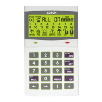
Table 5: Keypad Emergency Alarm Trigger’s K E Y PA D S E T U P The Solution 16i control panel can have a maximum of 8 Figure 10: LCD Display Showing All ICONs keypads connected via the LAN terminals. Each keypad must be set to a unique address before they will operate. -
Page 19: Keypad Tones
Trouble Tone 4 fast short beeps followed by a 5 second pause (repeat). Pressing any key on the keypad sounds Key Press one short beep, indicating that the key Tone press is accepted. Bosch Security Systems 09/11 BLCC500I... -
Page 20: Vandal Resistant Keypads
The reader connects to the control panel via the RS485 encrypted LAN and occupies a standard keypad position in the panel configuration. Figure 11: CP150B External Vandal Resistant Keypad Figure 12: PR111B Slim External LAN Reader Bosch Security Systems 09/11 BLCC500I... -
Page 21: Expansion Modules
E X PA N S I O N M O D U L E S CM704B Zone Expander Module The Solution 16i panel includes support for 1 x CM710B, 4 Way Relay Output Expander. The Solution 16i panel includes support for 1 x CM704B - 8/16 Zone Expansion module. -
Page 22: Figure 16: Cm195B Multi Rf Receiver Interface Module
The CM750B IP module allows you to interface the suitable for charging 12V 7Ah batteries. Solution 16i control panel to the building’s hard wired IP As with all LAN modules, the status of the CM720B is connection point using a CAT 5E connection cable. -
Page 23: Expansion Module Configuration
E X PA N S I O N M O D U L E CO N F I G U R AT I O N LAN module support for the Solution 16i panel requires that each module type is set to address 1. For example if a system has 1 x CM704B and 1 x CM720B installed, they should both be addressed as “module 1”. - Page 24 Solution 16i Installation Manual Installing the Hardware 2-12 Bosch Security Systems 09/11 BLCC500I...
-
Page 25: Figure 20: N/C No Eol Zone
ALARM (3K3 EOL) Figure 23: N/C Zone With Tamper ZN 2 The Above diagrams display the zone wiring configurations using Normally-Closed Alarm Note contacts and Normally-Open Alarm Contacts. When Figure 27: N/O Zone With Tamper Bosch Security Systems 09/11 BLCC500I... -
Page 26: Wiring Diagrams
The control panel supports up to 300 m of 24/0.20 (18 AWG) wire on these terminals. Common positive terminal for system 14 COMM+ outputs. This terminal is 2.5A PTC Fuse protected. Bosch Security Systems 09/11 BLCC500I... -
Page 27: Figure 28: Terminal Descriptions
/ Keyswitch Input 10-Pin Serial Connection Socket For Direct Link / Flash Programming etc. Zone Input Terminals Voice Module Connection Socket (Optional) Telephone Line Connection Socket (RJ12 6P4C) Telephone Line Connection Terminals Figure 28: Terminal Descriptions Bosch Security Systems 09/11 BLCC500I... -
Page 28: Figure 29: Wiring Diagram
ZONE 6 Connect To +12V Accessory Power ZONE 7 ZONE 8 RJ12 6P4C - RJ12 6P4C Phone Lead Connect To Telephone Line Mode 3 Premises Telephone Incoming Street Telephone Line Figure 29: Wiring Diagram Bosch Security Systems 09/11 BLCC500I... -
Page 29: Lan Overview
L A N O V E R V I E W CONTROL PANEL Connect to mains earth via 3 wire The Solution 16i panel communicates with other system EARTH plug pack transformer. module devices via the built in RS485 LAN or Local Area Network. -
Page 30: System Earthing
LAN A and LAN B terminals. In smaller installations where no LAN modules have been installed there is no need to fit the termination resistor on the control panel. The LAN must be terminated correctly for proper operation. Note Bosch Security Systems 09/11 BLCC500I... -
Page 31: Programming Overview
1) Enter Program Mode. [1234 + MENU] P R O G R A M M I N G O V E R V I E W The Solution 16i Control System incorporates a ICON 2) Enter the desired location number to program and style user interface and includes a text display to show press [OK]. -
Page 32: Programming Bit Options
Text descriptions are available for Area Name, Zone Name, 3) When prompted and the zone number User Name, Schedule Name, Holiday Name Prox Reader [Zn = ] 3 + [OK] Name and Output Name. Each name can have a maximum of 16 characters. Bosch Security Systems 09/11 BLCC500I... -
Page 33: Programming Telephone Numbers
Enter the required data and then press the [OK] key to finish. Press [MENU] at any time to exit without saving. Zn=3 The display will flash promting you to enter the required data value. Note Bosch Security Systems 09/11 BLCC500I... -
Page 34: Table 17: Domestic Dialing Defaults Settings
Keypads will display SErVIC on the screen when service mode is active. All Restore Reports Disabled Note Destination 1 TX Format Domestic Reporting Open / Close Reports Disabled (all areas) System Events Route Log Only Table 17: Domestic Dialing Defaults Settings Bosch Security Systems 09/11 BLCC500I... -
Page 35: Table 18: Dtmf Remote Control Functions
Make sure that the telephone being used to remotely control the panel is set to transmit DTMF tones when keys are pressed during the call. This option is disabled by default on some telephones. Bosch Security Systems 09/11 BLCC500I... -
Page 36: Table 19: Basic Reporting Code Reference
A complete reporting template is available on the Solution Upload/Download software in either Direct Link or Link CD, from your distributor or from Bosch. Your base Remote Link modes. For Direct Link you will need a CM900 station will need to create a specific reporting template Direct Link module which connects the panels serial port for this and other 2nd generation Solution panels. -
Page 37: Figure 40: System Trouble Display Sequence
LEvEl F20-Zone Expander # Zone Module Expander Missing IE001 LOSt F21-Zone Expander # Zone Module Expander Tamper IE001 cASE OPEn F30-Keyfob # RF Keyfob User Low Battery KF0xx F40-Panel # Panel Tamper P001 cASE OPEn Bosch Security Systems 09/11 BLCC500I... -
Page 38: Table 20: System Trouble / Fault Descriptions
Ethernet Module IP Changed Et001 chAnGE F102-Module # Ehternet Module No Connection Et001 cAbLE F103-Module # Ethernet Module IP Lockout Et001 LOch F104-Module # Ethernet Module IP Conflict Et001 InUse Table 20: System Trouble / Fault Descriptions Bosch Security Systems 09/11 BLCC500I... -
Page 39: Set Chime Zones
= Start Direct Connect = Customer Registration = Perform Dialer Test = Device MENU = Keypad Volume = Keypad Contrast = Keypad Backlight = Set Keypad Temp Alarm = LAN Status Figure 41: Text Menu Examples Bosch Security Systems 09/11 BLCC500I... - Page 40 P R O G R A M M I N G LO C AT I O N S R E F E R E N C E TA B L E The Solution 16i panel includes a simple text menu system which makes all levels of programming extremely easy.
-
Page 41: Zone Properties
5-3-8 User RAS Security PIN Dialler Reporting 5-4-0 TX Format Dest 1 5-4-1 TX Format Dest 2 5-4-2 Test Route 5-4-3 System Route 5-4-4 Emergency Route 5-4-5 Swinger Dialler 5-4-6 Burg Report Delay 5-4-7 Fire Report Delay 4-11 Bosch Security Systems 09/11 BLCC500I... -
Page 42: Table 21: Programming Locations And Descriptions
7-7-2 Keypad Idle Screen 7-7-3 Keypad Hi/Lo Temp 7-7-4 Installer Options 7-7-5 Language 7-7-7 Site Name System Testing UMI 7-9-0 Walk Test All Zones UMI 7-9-1 Battery Test Table 21: Programming Locations and Descriptions 4-12 Bosch Security Systems 09/11 BLCC500I... - Page 43 S E C TI O N 5 Access Programming The Solution 16i has 48 users which can each use any Users which are to be restricted are then assigned to the combination of pin, radio keyfob or a proximity token to same timer group number as the schedule.
-
Page 44: Table 22: User Default Programming Options
PIN. 3) Enter the user number then press [OK]. At factory default, each PIN is fixed to 4 digits in length. The default PIN for User 1 (Master user) is 2580. Bosch Security Systems 09/11 BLCC500I... - Page 45 EntPin 3) The PIN will always display 6 digits however only the number of digits corresponding to the global PIN Length setting are valid. 4) Enter the new PIN for the user you have selected. Bosch Security Systems 09/11 BLCC500I...
- Page 46 9. to the keypad. Ur009 PrSEnt 4) Press [OK] when finished. 4) Present the token at the keypad to learn the new token. Bosch Security Systems 09/11 BLCC500I...
- Page 47 This enables accurate auditing of user movements at a later time if required. Names are dEL? also used when reporting alarms and arm /disarm events in SMS and other text based reporting formats. Bosch Security Systems 09/11 BLCC500I...
-
Page 48: Table 23: Default User Names
1) Enter your Installer PIN + [MENU]. 2) Enter [1] + [4] + [2] + [OK] and enter the user number required to change, then press [OK]. 3) Use keys [1] to [8] to enable or disable the options required. Bosch Security Systems 09/11 BLCC500I... - Page 49 Setting this option to 0 will give the user 24 hour access to the system. 1) Enter your Installer PIN or Master PIN + [MENU]. 2) Enter [1] + [4] + [4] + [OK]. The keypad will display the Ur = prompt. Bosch Security Systems 09/11 BLCC500I...
- Page 50 The keypad will display the Ur = prompt. 3) Enter the user number you want to assign, then press [OK]. The keypad will display the current access groups assigned to the user via the zone indicators. -Bit- 4 5 6 Bosch Security Systems 09/11 BLCC500I...
- Page 51 This menu allows the installer to program the name or The factory default Installer PIN is 1234. location description of the prox reader. Up to 8 different Readers can be used on the Solution 16i via keypads that 1) Enter your Installer PIN + [MENU]. have built-in Readers.
- Page 52 2) Enter [1] + [6] + [3] + [OK]. Note seconds. 3) Enter the Reader required, then press [OK]. 4) Use keys [1] to [8] to toggle on or off the required reader options. 5-10 Bosch Security Systems 09/11 BLCC500I...
- Page 53 Present the token twice within 5 seconds and the area will arm in Part Mode. To Arm In Part Mode Present the token three times within 5 seconds and the area will arm in Part Mode 2. 5-11 Bosch Security Systems 09/11 BLCC500I...
- Page 54 Solution 16i Installation Manual Access Programming This page left intentionally blank 5-12 Bosch Security Systems 09/11 BLCC500I...
- Page 55 S E C TI O N 6 Area Programming he Solution 16i has 4 different areas each with its own The system outputs must be configured to operate for specific programmable options. their corresponding areas. The external siren, internal...
- Page 56 3) Enter the area number you wish to turn All On, then The system will now disarm all areas that are in the press [OK]. armed condition provided the user belongs or has access to the area. Bosch Security Systems 09/11 BLCC500I...
- Page 57 Only keypads programmed to sound the chime tone will or faulted. be heard when a zone programmed for chime is faulted. The master user can program which zones are monitored ch000 for chime alarms in MENU 3-0-3. Bosch Security Systems 09/11 BLCC500I...
-
Page 58: Table 24: Default Area Names
5) Repeat Step 4 until all options are programmed as 3) Enter the area number (1 to 4), then press [OK]. required, then press [OK] to save and exit or press [MENU] to exit without saving. Bosch Security Systems 09/11 BLCC500I... - Page 59 If open and close reports in Part Mode are programmed, the user ID number will report as 000. If a handover zone is triggered before an entry delay zone is triggered an instant alarm will occur. Bosch Security Systems 09/11 BLCC500I...
- Page 60 Alarm On Keyswitch Tamper (Only If System Armed) zones to be a keyswitch input. Reserved Reserved The above options are programmable per area. 1) Enter your intstaller PIN + [MENU]. 2) Enter [2] + [1] + [3] + [OK]. Bosch Security Systems 09/11 BLCC500I...
- Page 61 (audible or silent) has the area before the siren timer expires. triggered an alarm. Open/Close Reports For Part On When set, the panel will Send Open or Close reports when the system is armed in Part On mode. Bosch Security Systems 09/11 BLCC500I...
- Page 62 The number should be entered from left to signal will be sent when the area is next armed and the right with trailing zeros. exit time expires. 1) Enter your Installer PIN + [MENU]. 1) Enter your Installer PIN + [MENU]. Bosch Security Systems 09/11 BLCC500I...
- Page 63 For Service’ . To clear the trouble condition, the installer Test reports when a user enters/exits walk test mode and must enter and exit installer’s programming mode. test zones. 1) Enter your Installer PIN + [MENU]. Bosch Security Systems 09/11 BLCC500I...
- Page 64 Walk Test Fire Zones This option allows 24-hour fire zone assigned to the corresponding area to be tested during walk test. » » E N D S E C T I O N « « 6-10 Bosch Security Systems 09/11 BLCC500I...
-
Page 65: Table 25: Zone Configuration
S E C TI O N 7 Input Programming he Solution 16i is capable of controlling up to 16 inputs the same as for normally closed but there is an option in either hardwire or wireless configuration. Each provided that inverts the sealed state of a zone. - Page 66 4) Press the [OK] key to exit. The keypad will flash the Zn= prompt. Any zone(s) which are currently bypassed will also be flashing. If your system is programmed for multiple areas, the area icon will also be displayed. Bosch Security Systems 09/11 BLCC500I...
- Page 67 Part 2 On. Note At factory default all zones are monitored when you turn the area Part 2 On. Bosch Security Systems 09/11 BLCC500I...
-
Page 68: Table 26: Zone Defaults
ZO N E D E FAU LT TA B L E The table below lists the default values for all zone parameters in the Solution 16i. By default, zones 5 to 16 are set as Instant zones. Zones marked as Not Used do not require EOL resistors to be fitted. - Page 69 [MENU] to exit without saving. Note the exit time has exprired. Zones must be sealled at the end of exit time to trigger alarms. Bosch Security Systems 09/11 BLCC500I...
- Page 70 Refer to MENU 3-4-1 — Keyswitch Options to select the various options such as latching or momentary arm and/or disarm etc. When reporting back to base, the keyswitch user number will follow the actual zone number. Bosch Security Systems 09/11 BLCC500I...
- Page 71 4) Press [OK] to save and exit or press [MENU] to exit without saving. 2) Under user properties assign the users who you wish to have access to Access Group 5. Remember that you are able to assign users to more than one Access Group. Bosch Security Systems 09/11 BLCC500I...
- Page 72 2) Enter [3] + [1] + [7] + [OK], then enter the zone 4) Press [OK] to save and exit or press [MENU] to exit number required and press [OK]. The keypad will without saving. display the Report Options for the currently selected zone. Bosch Security Systems 09/11 BLCC500I...
- Page 73 3) Bypassed Zone restore when the area is disarmed. will occur from that zone. Only zones which have been locked out are prevented from triggering the sirens. Bosch Security Systems 09/11 BLCC500I...
- Page 74 A D D I N G R F S E N S O R S See MENU 7-4-3 — Swinger Siren to set the shutdown The Solution 16i panel supports a wide range of 3rd party count. wireless movement sensors, door contacts and smoke...
-
Page 75: Eol Value
[OK] to save and exit or press triger [MENU] to exit without saving. 3) Once a signal is received the following information will be displayed. gOOd Signal can = Good, Average or Move (Relocate) 7-11 Bosch Security Systems 09/11 BLCC500I... -
Page 76: Keyswitch Options
The default is set to Off. Alarm On Tamper This option allows tamper circuits on RF sensors and hardwire zones to sound an alarm when faulted when their corresponding area is turned off (disarmed). 7-12 Bosch Security Systems 09/11 BLCC500I... -
Page 77: Input Type
1 2 3 02 = Momentary - On/Off (RF Relay) 03 = Digiflex RF On/Off 04 = Bosch Serial RF Receiver 3) Use the numeric keys [1] to [8] to toggle on or off 05 = Crow Serial RF Receiver the option required. -
Page 78: Input Testing
The keypad will display the Zn = prompt. 3) Enter the zone number you want to test, then press [OK]. test 4) Fault and restore the zone to be tested. If the zone test was sucessful, the keypad will display PASS. 7-14 Bosch Security Systems 09/11 BLCC500I... -
Page 79: Output Programming
S E C TI O N 8 Output Programming he Solution 16i is capable of controlling up to 8 outputs. O U T P U T CO M M A N D S The first 4 outputs are on the main control board and Outputs >... -
Page 80: Turn Output On/Off
Repeat step 3 for any additional outputs that you need to control. 4) Press [OK] to exit. 3) Enter the output number (1 to 8) you want to program, then press [OK]. StrObe Bosch Security Systems 09/11 BLCC500I... - Page 81 This event type will cause the output to operate if the panel fails to report to destination1 or 2 or both. The panel will try to send the report as many times as set in Bosch Security Systems 09/11 BLCC500I...
- Page 82 See Timer is active. The output will reset when the entry MENU 4-1-2 — Event Assignment for infomation on how timer expires or the corresponding area is disarmed. to set the zone to monitor. Bosch Security Systems 09/11 BLCC500I...
- Page 83 Part On zones are sealed. The output will reset if any area is armed or if any Part On zone Bosch Security Systems 09/11 BLCC500I...
- Page 84 See MENU 55 – Output Pre Alert 2-1-5 — Strobe Trigger option. This event type will cause the output to operate when the output pre-alert timer is active and will reset when the pre-alert timer expires. Bosch Security Systems 09/11 BLCC500I...
- Page 85 15 = Toggle On / Toggle Off The output polarity programs how the output will operate. Only one option (0 – 15) can be programmed per output. See the Output Polarity description for more detailled information. Bosch Security Systems 09/11 BLCC500I...
- Page 86 The output will toggle off when the event occurs Output is normally open circuit and will switch to GND again. This polarity does not follow any time parameters. when the event occurs. The output will reset when the Bosch Security Systems 09/11 BLCC500I...
-
Page 87: Table 29: Example - Output One Shot Timer
For Example you may want a strobe output limit. A restore report will be sent when the current to operate for 1 hour, Either of the examples below will overload condition no longer exists. achieve the 1 hour time. Bosch Security Systems 09/11 BLCC500I... - Page 88 StrObe Siren ALARM ALARM During the 60 second strobe test, the keyapd will display both the word ‘Strobe’ and also the alarm icon. The keypad will display ‘Siren’ and the alarm icon 8-10 Bosch Security Systems 09/11 BLCC500I...
-
Page 89: Event Type
O U T P U T D E FAU LT TA B L E The table below list the default values for all Output parameters in the Solution 16i. Outputs 1 to 3 are High current digital outputs and Output 4 is the onboard relay output. Outputs 5 to 8 are only available if the optional Output Relay Expander Boards (CM110) are fitted. - Page 90 Solution 16i Installation Manual Output Programming This page left intentionally blank 8-12 Bosch Security Systems 09/11 BLCC500I...
- Page 91 S E C TI O N 9 Comms Programming he Solution 16i has a built in dialler that connects CO M M S P R O G R A M M I N G CO M M A N D S directly to a standard PSTN telephone line.
- Page 92 1) Enter your Installer PIN or Master PIN + [MENU]. This feature requires firmware version 2.10 or higher. 2) Enter [5] + [0] + [2] + [OK]. If call forwarding is off, the keypad will display: Note IS OFF Bosch Security Systems 09/11 BLCC500I...
- Page 93 2) Enter [5] + [1] + [1] + [OK]. The keypad will display 2) Enter [5] + [1] + [3] + [OK]. The keypad will display the current Primary Telephone Number for the current Primary Telephone Number for Destination 1. Destination 2. Bosch Security Systems 09/11 BLCC500I...
- Page 94 Up to 3 Phone numbers can be entered for Domestic dialing. Press [OK] after each telephone number is The keypad will display the current call forward on Note entered to save and move to the next number. number sequence. A61PA2 Bosch Security Systems 09/11 BLCC500I...
- Page 95 2) Enter [5] + [2] + [0] + [OK]. The keypad will display the current number of call attempts per For other countries please substitute the appropriate destination. (Default = 6). commands after consultaion with your telephone Note company. Bosch Security Systems 09/11 BLCC500I...
- Page 96 This option configures the panel to start dialling as soon as it detects dial tone on the line. This can speed up the dialing process by up to 3 seconds. If no tone is detected the panel will blind dial after 4 seconds. Bosch Security Systems 09/11 BLCC500I...
- Page 97 3) Use the arrow and number keys to move and change text. At any time you can press the [OFF] key to clear the text from the current cursor position to the end of the line. Bosch Security Systems 09/11 BLCC500I...
- Page 98 Solution Link session. If the event log reaches 100% capacity before a Solution Link RAS session is established then the system will send a Bosch Security Systems 09/11 BLCC500I...
- Page 99 Answer Machine Bypass Answering machine bypass allows you to establiish a RAS connection to a panel when there is an answering machine or facsimile machine connected on the same telephone line. Bosch Security Systems 09/11 BLCC500I...
- Page 100 3 beeps in accending frequency if the panel is in the disarmed condition. Press [0] + [#] to arm. You will hear 3 beeps in decending order when the panel arms. 9-10 Bosch Security Systems 09/11 BLCC500I...
-
Page 101: Table 32: Dtmf Remote Control Functions
Make sure that the telephone being used to remotely control the panel is set to transmit DTMF tones when keys are pressed during the call. This option is disabled by default on some telephones. 9-11 Bosch Security Systems 09/11 BLCC500I... - Page 102 CLI telephone numbers can be programmed, each having a maximum of 32 digits. 1) Enter your Installer PIN + [MENU]. 2) Enter [5] + [3] + [7] + [OK]. The keypad will prompt you to edit CLI number 1. 9-12 Bosch Security Systems 09/11 BLCC500I...
- Page 103 Format required then Press [OK] to save and exit or press [MENU] to exit without saving. 3) Use the numeric keys to enter the Test Route required, then press [OK] to save and exit or press [MENU] to exit without saving. 9-13 Bosch Security Systems 09/11 BLCC500I...
- Page 104 [MENU] to exit without saving. 3) Using the numeric keys, enter the new report delay time then press [OK] to save and exit or press [MENU] to exit without saving. Valid entires are 0 to 255 seconds 9-14 Bosch Security Systems 09/11 BLCC500I...
- Page 105 3) Use the numeric keys [0] to [9] + [←] and [→] keys to program the new MyAlarm IP Address, then press [OK] to save and exit or press [MENU] to exit without saving. 9-15 Bosch Security Systems 09/11 BLCC500I...
- Page 106 Open / Close Reports Zone Alarm Reports Zone Trouble Reports System Reports Access Events Reserved Reserved Reserved Email reporting requires firmware version 2.10 or higher and will only operate within Australia. Note 9-16 Bosch Security Systems 09/11 BLCC500I...
- Page 107 4) The keypad will display the current poll rate. number for Destination 1 and/or Destination 2 so that the control panel can communicate to the base station receiver. The port number must be 5 digits long within the range - to 65535. 9-17 Bosch Security Systems 09/11 BLCC500I...
- Page 108 TCP/ IP to the base station receiver for both Destination 1 and/ or Destination 2. The retry count can be programmed between 1 and 15 (0=Disabled). 1) Enter your Installer PIN + [MENU]. 9-18 Bosch Security Systems 09/11 BLCC500I...
- Page 109 Master user programs this menu, the keyapd will only display the option to program the user IP address: 3) Select the which IP port number that you want to change (installer or user, then press [OK] to enter. 9-19 Bosch Security Systems 09/11 BLCC500I...
- Page 110 This option allows the control panel to connect with Solution Link via the optional ethernet module. d= 060 RAS Only If Disarmed This option allows a RAS connection via TCP IP connection only when the system is disarmed. 9-20 Bosch Security Systems 09/11 BLCC500I...
- Page 111 Period, then press [OK] to save and exit or press 2) Enter [5] + [9] + [1] + [OK]. The keypad will display [MENU] to exit without saving. the current hour of the day that the test report is set. 9-21 Bosch Security Systems 09/11 BLCC500I...
- Page 112 03 = Report Events To Destination 1 & Destination 2 + Log 04 = Report Events To Dest 2 If Dest 1 Fails + Log This menu programs which destination will be used to send both manual and automatic test reports. 9-22 Bosch Security Systems 09/11 BLCC500I...
- Page 113 The system display CP001 which represents Keypad secured, the keypad will display the following. number 1 on the system. Press [OK[ to view. SecOff The display will show each parameter for the device one at a time. 10-1 Bosch Security Systems 09/11 BLCC500I...
- Page 114 3) Press the the [↑] and [↓] keys to adjust the contrast. save and exit or press [MENU] to exit without Min = 1, Max = 3. saving. 4) Press [OK] to save and exit, or press [MENU] to exit d =1 without saving. 10-2 Bosch Security Systems 09/11 BLCC500I...
- Page 115 ™ Good Morning Greeting = 00:00 to 11:59 armed and when the Area Icon is OFF or not visible the ™ Good Afternoon Greeting = 12:00 to 17:59 corresponding area is disarmed. ™ Good Evening Greeting = 18:00 to 23:59 10-3 Bosch Security Systems 09/11 BLCC500I...
- Page 116 When the corresponding warning alert tone when the exit timer is running. The number on the keypad is on then the option is tone will stop when the timer expires. selected. 10-4 Bosch Security Systems 09/11 BLCC500I...
-
Page 117: Table 33: Keypad Emergency Keys
3) Use the numeric keys to enter the Access Group Emergency Alarm has been triggered via the keypad. that you want to assign the keypad to. 4) Press [OK] to save and exit or press [MENU] to exit without saving. 10-5 Bosch Security Systems 09/11 BLCC500I... - Page 118 3) Use the numeric keys [1] to [8] to turn on and off any RF device that fails to report within the supervision the features as required. When the corresponding time. number on the keypad is on then the option is selected. 10-6 Bosch Security Systems 09/11 BLCC500I...
- Page 119 Setting this option will cause the panel to send an RF Device Faulted report to the base station when the devices tamper curcuit is tripped. A restore report will be sent when the tamper circuit is resealled. 10-7 Bosch Security Systems 09/11 BLCC500I...
- Page 120 L651 To test another transmitter, repeat step 3. Options MENU 6-5-1 4) Press [OK] or [MENU] to exit this command. 00 = Reserved 01 = Reserved 02 = Reserved Reserved for future use. 10-8 Bosch Security Systems 09/11 BLCC500I...
- Page 121 3) Use the numeric keys [0] to [9] + [←] and [→] keys to program the 12 digit subnet mask number, then press [OK] to save and exit or press [MENU] to exit without saving. 10-9 Bosch Security Systems 09/11 BLCC500I...
- Page 122 3) Use the numeric keys [0] to [9] + [←] and [→] keys [OK] to save and exit or press [MENU] to exit to program the 8 digit NNC number, then press without saving. [OK] to save and exit or press [MENU] to exit without saving. 10-10 Bosch Security Systems 09/11 BLCC500I...
- Page 123 This option allows the control panel to report via the dialler when the ethernet module fails to send a poll to the base station. » » E N D S E C T I O N « « 10-11 Bosch Security Systems 09/11 BLCC500I...
- Page 124 Solution 16i Installation Manual Device Programming This page left intentionally blank 10-12 Bosch Security Systems 09/11 BLCC500I...
- Page 125 5) To return to the trouble list, press the [MENU key, or to exit completely and return to the normal state, press and hold the [MENU] key down for 2 seconds. 11-1 Bosch Security Systems 09/11 BLCC500I...
- Page 126 Defaulting the panel will NOT erase any history events P001 that are currently stored in the panel. 1) Enter your Installer PIN + [MENU]. 2) Enter [7] + [0] + [4] + [OK]. The keypad will display: 03 jAn FdEF? 11-2 Bosch Security Systems 09/11 BLCC500I...
- Page 127 5) Use the numeric keys to enter the last 2 digits of the When you exit programming mode, the keypad will current year (01 -99). display ‘SEruic’ whilst service mode is active. The keypad will display the currently programmed hour of the day in 24hr time. 11-3 Bosch Security Systems 09/11 BLCC500I...
-
Page 128: Table 34: Daylight Savings Dates - Australia
WW =05 December = 12) that Summer Time ends. WW =05 4) Enter the number of the week (First Week = 1 / Last Week = 5) in that month that Summer Time starts. 11-4 Bosch Security Systems 09/11 BLCC500I... - Page 129 Programming the entry guard 1) Enter your Installer PIN + [MENU]. time as zero will disable this feature. 2) Enter [7] + [2] + [1] + [OK]. The keypad will display the current Entry Time 1 delay. 11-5 Bosch Security Systems 09/11 BLCC500I...
- Page 130 2) Enter [7] + [2] + [6] + [OK]. The keypad will display 4) Press [OK] to save and exit or press [MENU] to exit the current senior watch time. (default = 0 hours). without saving. d =000 11-6 Bosch Security Systems 09/11 BLCC500I...
- Page 131 AC Fail to the base station if the mains power has been 1 2 3 4 missing for a period of 1 minute. A restore report will be sent once the mains power has been restored for one 11-7 Bosch Security Systems 09/11 BLCC500I...
- Page 132 1Amp. Display LAN + Current Overload Setting this option allows the keypad to display a system trouble message when the current load on the LAN+ terminal exceeds its maximum rating of 1Amp. 11-8 Bosch Security Systems 09/11 BLCC500I...
- Page 133 SPd=09 2) Enter [7] + [4] + [3] + [OK]. The keypad will display the current Swinger Siren count. d= 03 3) Use the up and down arrow keys to change the siren speed. 11-9 Bosch Security Systems 09/11 BLCC500I...
-
Page 134: Table 35: Default Schedule Names
S YS T E M S C H E D U L E S Schedule 8 NAme The Solution 16i has 8 schedules each with a start and Table 35: Default Schedule Names stop time as well as the day of the week and holidays. - Page 135 8) Use the [←] and [→] keys to confirm programming can be programmed. and then press [OK] to exit. 1) Enter your Installer PIN + [MENU]. 2) Enter [7] + [5] + [3] + [OK]. The keypad will display the sh = prompt. 11-11 Bosch Security Systems 09/11 BLCC500I...
- Page 136 Timer Group to restrict user access to doors and areas. The INDEX defines the Timer Group to link to. See MENU 1-4-4 — Timer Group for information on assigning users to timer groups. 11-12 Bosch Security Systems 09/11 BLCC500I...
-
Page 137: Table 36: Default Holiday Names
S YS T E M H O L I D AYS System > Holidays > hOtime The Solution 16i has provision for up to 8 individual holiday Start / Stop Dates MENU 7-6-1 time periods which can be used to allow or deny access... - Page 138 [MENU] to exit without saving. Alarm On LAN Fail Setting this option allows the panel to sound an alarm when a device connected to the LAN failed to 11-14 Bosch Security Systems 09/11 BLCC500I...
- Page 139 If any trouble events are still in effect at 7am, the keypad will begin sounding the trouble alert to notify the user The keypad will display the current Hi temperature of the problem. The function is primarily for use in setting. residential installations. hi=20 11-15 Bosch Security Systems 09/11 BLCC500I...
- Page 140 When the corresponding number on the keypad is on then the option is selected. 2) When all options are programmed, press [OK] to save and exit, or press [MENU] to exit without saving. 11-16 Bosch Security Systems 09/11 BLCC500I...
- Page 141 [OFF] key. 4) When the site name is complete, press [OK] to save and exit, or press [MENU] to exit without saving. 11-17 Bosch Security Systems 09/11 BLCC500I...
- Page 142 If the test fails the keypad will display. If this happens display PASS. you should contact your installer. PASS FAil 4) Press [OK] to exit. 3) Press [OK] to exit. » » E N D S E C T I O N « « 11-18 Bosch Security Systems 09/11 BLCC500I...
- Page 143 The following example show how to configure the controlled door using a single digit code. The example Solution 16i to allow control of a grage door as well as assumes User 10 and Output 5 are being used. (Output 5 arm and disarm functions using a 4 Button Keyfob.
- Page 144 1-6-1. callers line information if you don’t specifically request 2) Set output 5 to Event type = 60 -Access Group and and enable this feature with your telco line provider. Access Assignment = 4. 12-2 Bosch Security Systems 09/11 BLCC500I...
- Page 145 5) Program the destination route for each event type which is required to report to SMS. By default all event types report to route 1. » » E N D S E C T I O N « « 12-3 Bosch Security Systems 09/11 BLCC500I...
- Page 146 Solution 16i Installation Manual Programming Examples This page left intentionally blank 12-4 Bosch Security Systems 09/11 BLCC500I...
- Page 147 Specifications S P E C I F I C AT I O N S Panel Solution 16i (Part Number CC500) Voltage Input 16-18V AC 50-60Hz - 24VA External Power Adaptor or 220-240V AC to 18V AC 50-60Hz - 24VA Internal Transformer (Primary Power Source)
- Page 148 1 x Tamper Switch Bracket 1 x Pack PCB Mounting Clips (5 pc/pack) 1 x Product Identification Label Available Solution 16i Installation Manual Part Number BLCC500I Separately Solution Link (RAS) Software Part Number: SW500B 13-2 Bosch Security Systems 09/11 BLCC500I...
- Page 149 Arm Only Code ....... . . 5-7 14-1 Bosch Security Systems 09/11 BLCC500I...
- Page 150 Name ......... . 11-13 Installer PIN Arming Not Allowed....10-4 14-2 Bosch Security Systems 09/11 BLCC500I...
- Page 151 Part Mode Entry Time ......11-5 Add 5-5 14-3 Bosch Security Systems 09/11 BLCC500I...
- Page 152 ZONE CONFIGURATION TABLES ....7-1 Terminal Descriptions ......3-2 14-4 Bosch Security Systems 09/11 BLCC500I...
- Page 153 Zone Type ........7-5 14-5 Bosch Security Systems 09/11 BLCC500I...
- Page 154 Bosch Security Systems 25 Huntingwood Drive Huntingwood, NSW 2128 Australia Phone: +612 9672 1777 Facsimile: +612 9672 1717 © 2011 Bosch Security Systems BLCC500I 920228 Issue FTR1.2...
Need help?
Do you have a question about the Solution 16i and is the answer not in the manual?
Questions and answers