
Related Manuals for Raycus RFL-C30000M-CE


Summary of Contents for Raycus RFL-C30000M-CE
- Page 1 Global Version Continuous-Wave Fiber Laser User Guide RFL-C30000M-CE Wuhan Raycus Fiber LaserTechnologiesCo., Ltd.
-
Page 2: Table Of Contents
CONTENTS 1 Safety Information ..........................4 1.1 Security Label ..........................4 1.2 Laser Safety Grade .......................... 6 1.3 Optical Safety ..........................7 1.4 Electrical Safety ..........................7 1.5 Other Safety Rules .......................... 7 2 Product Description ..........................8 2.1 Features ............................8 2.2 Package Parts ...........................8 2.3 Unpacking and Inspection .......................8 2.4 Operation Environment ........................ - Page 3 7.2 Laser Communication Protocol (Network Port & Serial Port) ............. 42 8 8 The instructions of Raycus software ..................... 47 8.1 The main menu of the Raycus software display ................47 8.2 Selecting the laser ..........................48 8.3 Selection of Raycus software working mode ................49 8.4 anguage Selection ..........................49...
- Page 4 8.6.6 Output parameter reading and setting area .................54 8.7 Laser circuit status display area ....................55 8.8 Laser module enable display area ....................55 8.9 XP1 Interface Status Indication .....................56 8.10 Log .............................. 56 8.10.1 Downloading Historical Fault Records ................56 8.10.2 Downloaded file address ....................
-
Page 5: Safety Information
1 Safety Information Thank you for choosing Raycus Fiber Laser. This user manual provides you with important safety, operation, maintenance and other relevant information. Please read the manual carefully before using this product. To ensure safe operation and optimum product operation, please observe the following cautions and warnings as well as other information within this manual. -
Page 6: Laser Safety Grade
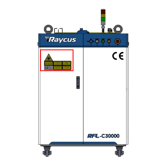
CAUTION: Describes a hazard that leads to general injury to people or damages to product. English(30000W) English English Chinese(30000W) Chinese Chinese 3: Class 2 Laser Product Label-5mW 1:Laser Emit Head 2: Type 4 Laser Product Red Laser 4: CE Authentication 5: ID Label (30000W) 6: Laser Radiation Hazard 7:Electrical Hazard... -
Page 7: Optical Safety
laser is not visible, the beam will cause irreparable damage to the retina or cornea, so appropriate and certified laser safety glasses must be worn throughout the laser emitting. WARNING:Users must use appropriate laser goggles when operating this device. The laser goggles should be selected according to the range of wavelength emitted from this product. -
Page 8: Product Description
Once you find that there is an abnormality in the external cabinet, please inform Raycus Company in time to deal with it as soon as possible. Please double check if each listed content is inside the package; and contact Raycus as soon as possible if there are any issues. -
Page 9: Operation Environment
2.4 Operation Environment The operation conditions are listed as the Table 1. Table 1 The operation environment conditions for the laser Type RFL-C30000M-CE Supply voltage (V) Three-phase four-wire system AC 323V~AC 437V, 50/60Hz (including PE) Power supply capacity (kVA) >125... -
Page 10: Features
Failure to follow the instructions may cause laser power loss, such loss is not covered by warranty. 2.6 Features The optical, electrical and other properties of RFL-C30000M-CE lasers are listed in Table 2. Table 2 Product technical data sheet Optical properties... -
Page 11: Installation
Operating Ambient 10~40 Temperature (°C) Humidity (%) 30~70 Storage Temperature -10~60 (°C) Cooling Water cooling Method 3 Installation 3.1 Dimensions The main body dimensions of RFL-C30000M-CE continuous fiber laser are shown in Figure 2(a). (a.1) Front view (a.2) Rear view... -
Page 12: Installation Rule
If the output cable lens is dirty, the lens must be cleaned. It is forbidden to disassemble the output lens by anyone other than staff in Raycus, otherwise the warranty will be invalidated. - Page 13 Before the laser is powered on, Please check if the power supply has the correct voltage (380VAC±10%, 50/60Hz, See “Table 2 Product technical data sheet” for details.), whether the grounding line is well grounded; Connect the power cable and control cable to the product when power supply is OFF; Connect the cooling system to the laser and output optical cable head according to the water inlet and outlet signs;...
- Page 14 Lifting Ring Lifting Ring Horizontal Horizontal Adjustment Adjustment Figure 4 Laser lifting ring and horizontal adjustment caster Caster CAUTION: All the cables can only be connected when power supply is off. Hot plug may damage the device. CAUTION: (1) The placement of the laser output cable should be as natural as possible, and the output cable should not be twisted;...
-
Page 15: Protective End Cap Of Output Cable And Using Description
Factory end cap type Use end cap type Type A end cap Type B end cap RFL-C30000M-CE (with protective (without protective window ) windows ) Note: According to the difference of the protective end cap of the cable in the actual use of the customer, some models need to replace the protective end cap. -
Page 16: Pre-Installation Cleaning Instructions For Output Cables
Figure5 Schematic diagram of the protective end cap of the optical cable 3.3.2 Pre-installation Cleaning Instructions for Output Cables A) Preparation tools Cleaning agent: absolute ethanol, or isopropyl alcohol. Cleaning tools: cleaning cotton swabs, dust-free paper, compressed air bottles, etc. B) Steps a) Clean workbench should be turned on for at least 5 minutes, and the output optical cable should be taken out of the black packaging box, as Figure 6. - Page 17 Figure 7 The output optical cable placed in the clean bench with the ventilation turned on c) Remove the white dust cap and place it face down on new lint-free paper. Note: The dust-free paper is for one-time use, and there is a risk of dust falling if it is used multiple times.
- Page 18 Figure 9 Remove the A -type end cap on the optical cable e) Check the cleanliness of the end caps in this state. If the cleanliness is not enough, please clean the end caps. Please refer to the cleaning method: http://www.raycuslaser.com/view/1852.html Reference video:https://mp.
-
Page 19: Cooling Requirements
Minimum flow (L/min) (Bar) (kW) (mm) (℃) >215 BOTTOM 4~6 RFL-C30000M-CE ≥60 Φ32 22±1 >123 >92 Requirements on cooling water: The laser source cooling water connection is shown in Figure 11, and the arrow direction indicates the water flow direction;... - Page 20 If ambient temperature is below -10℃, the chiller with both heating and cooling functions must be used, and keep it in full-time operation; Figure 11 diagram of laser cooling system connection Water cooling requirements for output optical cables: Water flow requirements: QP output cable water flow is between 3.0L/min and 4.0L/min; Water cooling pressure: 0.4Mpa~0.6Mpa at the water inlet;...
-
Page 21: Using The Product
(2) Before turning on the laser, the cooling system must be working properly and the water temperature should be suitable for the temperature. 4 Using the Product Please log in to the official website of Raycus to download the new Raycus software and the Raycus software user manual. Website: http://www.raycuslaser.com 4.1 Front Panel... - Page 22 ⑥ ① ② ③ ④ ⑤ Figure 12 Front view of the panel Note: ①-REM/OFF/ON ②-POWER ③-LASER ④-ALARM ⑤-STOP ⑥-INDICATOR LIGHT REM/OFF/ON: The key switch, the main control switch of the laser. Insert the key and turn it to the "ON"...
-
Page 23: Rear Panel
INDICATOR LIGHT: After the main power supply of the laser is powered on, the green indicator light is on when the laser is Ready; when the laser is emitting light, the red indicator light is on; when the laser has a fault, the yellow indicator light is on, accompanied by an alarm sound. 4.2 Rear Panel Figure 13 shows the rear panel. -
Page 24: Power Connection
①-INTERFACE: This interface provides all control signals, including: RS232 communication, laser on/off control, laser remote control mode selection, analog control, modulation signal, Interlock interface, etc.This socket comes with a protective cover and a lock. When you are not using the product, you can cover the power input socket with the protective cover and lock it with the lock. -
Page 25: Control Interface Definition
RFL-C30000M-CE 激光器交流输入线接口定义及参数要求 Interface definition Identification Wire diameter Color AC380V-L1 35mm Brown AC380V-L2 35mm Black AC380V-L3 35mm Gray 35mm Kelly 安全地 The standard length of power cord provided by the company is 15m 4.4 Control Interface Definition This type of laser does not provide a control signal line, except a control signal connector. The appearance of the joint is shown in Figure 14. - Page 26 4.4.1 Safety XP2 Interface 24-pin safety interface, with remote control system power-on, remote main power power-on and active and passive output of some lasers. The detailed interface definition is shown in Table 6. Table 6 XP2 security interface definition Pin No. Type Description Output control, voltage input signal;...
-
Page 27: Hardwiring Xp1
4.4.2 HARDWIRING XP1 64 pin hardwire interface, control signal input and output interface of laser in remote mode. Input high level is greater than 18V valid, input low level is less than 3V valid.Specific interface definitions are shown in Table 7 below. Table 7 XP1 hardwire interface definition Interface Definition Type... - Page 28 Stop programming In programming mode, program execution is Input signal Mode terminated immediately when A7 is high. Hardwired address for selecting a stored program Set program A8~A14 Input signal number. A8 is the lowest bit and A14 is the Number highest bit.
- Page 29 Laser program is ended when B10 is high. B10 clears Program ending Output signal when the A2 is invalid. Abnormal Wave Laser program is ended abnormally when B11 is high. Output signal Mode Termination B11 can be cleared when the A4 is high. Synchronous Output signal Sync signal output in programming mode.
-
Page 30: Serial Rs232 Interface
The 9-pin serial interface RS232 is used for the communication between the laser and the Raycus software. It can be used to communicate with the Raycus software or the software of the Raycus software which integrates the communication protocol of Raycus. The definition is as follows. -
Page 31: Introduction To Safety Interlock
4.5 Introduction to Safety Interlock Raycus’ product is designed with a safe interlocking loop, which is a two-channel system with output monitoring and manual reset. When the safety interlocking circuit is open, the safety circuit will disconnect the working power of the optical module, that is, the main power supply of the optical module. -
Page 32: Control Mode Selection
5 Control Mode Selection The Raycus high-power CW laser has two control modes: namely ON mode and REM mode. Users can select the mode to be entered through the key on the front panel. -
Page 33: On Mode
XP1-A1is high level, XP1-A6 is high level; XP1-A1is high level, XP1-A3 is low level or suspending; XP1-A1 is high level, XP1-A8~A14 is not all low level; Emit laser: Send "EMON" by communication, or clickbutton of Emission “ON” on the PC software Turn off the laser: Send "EMOFF"... -
Page 34: Programming Mode
When the red light is on, the laser cannot be set to “Ready”. Only after the red light is turned off the laser can be set to “Ready”. (This limit can be changed, please contact Raycus Engineer). 5.5 Programming Mode In “ON”... -
Page 35: Programming Mode
When the red light is on, the laser cannot be set to Ready. Only after the red light is turned off the laser can be set to “Ready”. (This limit can be changed, please contact Raycus Engineer). 5.6.4 Programming Mode When A1 of XP1 is set high and A8-A14 is not 0, the laser is in “Programming Mode”. -
Page 36: Laser Operating In External Control Mode
Turn the knob switch on the rear panel to“ON” b) Turn the key switch to“ON” c) Open the Raycus software d) Click the guide laser “ON” button to view the guide laser e) Turn off “AD” mode and turn on “External Control” mode (this mode can be memorized after power off) f) Click the main power “ON”... -
Page 37: In On Mode, The Laser Emission Power Is Externally Controlled By Analog Signal
Turn the knob switch on the rear panel to“ON” Turn the key switch to“ON” Open the Raycus software Click the guide laser “ON” button to view the guide laser Turn on the “AD” mode and turn on “External Control” mode (this mode can be memorized after power off) f) Click the main power “ON”... -
Page 38: Laser Operating In External Control Programming Mode
Start waveform at the rising edge of MOD signal. NOTE: The high-level time of MOD must be greater than the program running time. If MOD gives a falling edge in advance, the Raycus software will display that the laser program is abnormally terminated. -
Page 39: Set The Power Analog Quantity In Rem Mode To Control The Laser Emission
0V and turn off the guide laser f) XP1-C1 is connected to 24V, and the main power is turned on (operator can also directly press the LASER button, or clicks the main power “ON” on the Raycus software) Waiting for “Ready”... -
Page 40: Power Communication Setting In Rem
Figure 20 Timing diagram 6.6 Power Communication Setting in REM Figure 21 Wiring diagram of power internal control and laser emission external Operations Steps: Turn the knob switch on the rear panel to“ON” Turn the key switch to“REM” Short-circuit pin 8/9 on XP2 XP1-A1 connects to 24V Connect XP1-A5 to 24V and turn on the guide laser;... -
Page 41: Programming Mode In Rem Mode
“LASER” button, or clicks the main power “ON” on the Raycus software) Waiting for “Ready” The Raycus software sets the power, XP1-A2 is connected to 24V, and the control board card outputs MOD signal 6.7 Programming Mode in REM Mode... -
Page 42: Rs232 And Ethernet Communication Command
Figure 23 Timing diagram 7 RS232 and ETHERNET Communication Command 7.1 Port Configuration RS-232 configuration is as follows: Baud rate :9600, data bit :8, stop bit :1, no parity bit and no control flow. Ethernet port is configured as follows: Default laser IP address :192.168.0.10 Laser port :10001 7.2 Laser Communication Protocol (Network Port &... - Page 43 Table 12Specific protocol contents and command examples of laser Command Description Command example Send: ‘ABF\r’ Aiming Beam OFF –Turn off red Return: ‘ABF\r’ Send: ‘ABN\r’ Aiming Beam ON – Turn on red Return: ‘ABN\r’ Send: ‘DEABC\r’ DEABC Disable External Aiming Beam Control Return: ‘DEABC\r’...
- Page 44 Set Diode Current (%) Send: ‘SDC 100\r’ The set value must be less than 100% and above Return: ‘SDC:100\r’ the minimum current setting value, which can be Other return values: set to 0. If the set value is greater than 100, the ‘ERR: Input Err\r’...
- Page 45 Disable Calibration Mode Send: ‘DCM\r’ (AD analog response time is less than 100 us in Return: ‘DCM\r’ this mode) Send: ‘BGM\r’ Others Command Error Return: ‘Command Err!\r’ Read Device Status – Read the product status. A return value of 32-Bit digital information.
- Page 46 Modulation mode=on Normal Bit 13 Leakage sensors 1 leaking Normal Bit 14 Leakage sensors 2 leaking No laser Bit 15 Laser is power on Gate mode=off Bit 16 Gate mode=on AC input normal Bit 17 AC input abnormal External Emission control=off Bit 18 External Emission control=on Normal...
-
Page 47: 8 The Instructions Of Raycus Software
8 8 The instructions of Raycus software 8.1 The main menu of the Raycus software display The main interface of the Raycus software display is shown in Figure 24. Basic usage method of Raycus laser Raycus software: a) Click "Mode", select "Control Mode", and click "OK" to enter the control mode;... -
Page 48: Selecting The Laser
IP addresses on the upper computer by selecting the IP address. Click Select Laser on the upper computer toolbar, as shown in Figure 25. After confirming the IP address, you can connect to the laser. After successful connection, see Figure 26. The factory default IP address of Raycus Laser is 192.168.0.10... -
Page 49: Selection Of Raycus Software Working Mode
8.3 Selection of Raycus software working mode The laser operation mode is set through the Raycus software, and its operation menu is shown in Figure 27. The definitions of various modes are shown in Table 12. When the display programming mode is selected, the waveform editing menu will be displayed on the software. -
Page 50: About
8.5 About Information such as laser factory time, model, laser serial number, master serial number, key version number, and system information can be queried in the "About" item of the Raycus software. The specific display menu is shown in Figure 29. -
Page 51: Main Status Display Area
8.6 main status display area The main status display area of the laser is shown in Figure 30, and the display content is shown in Table Figure 30 Schematic diagram of the main display area of the laser Table 13 Display Contents and Meaning of the Main Display Area of the Laser Display Content Meaning Output power [%]... -
Page 52: Display Area For Accumulated Working Time Of Laser
Display Meaning red - indicates that the emergency stop button on the front panel of the laser is pressed; Emergency stop Grey - indicates that the emergency stop button on the front panel of the laser has been reset The status of output green - the interlock contact on the output optical cable head is closed;... -
Page 53: Laser Power On, Mode Selection, Light Output Control Area
Figure 32 Display menu for accumulated working time of laser 8.6.3 Laser power on, mode selection, light output control area The display area for laser power on, mode selection, and light output control is shown in Figure 33, and the display content is shown in Table 15. Figure 33 Display area for laser power on, mode selection, and light output control Table 15 Display content and meaning of laser power on, mode selection, and light output control display area... -
Page 54: Slow Rise And Slow Fall Parameter Area
8.6.4 Slow rise and slow fall parameter area The display menu of the laser power ramp up ramp down parameter setting area is shown in Figure 34. Click Read Parameters to read the power rise and fall times stored in the laser. Click Set Parameters to set a new power up and down time. -
Page 55: Laser Circuit Status Display Area
Figure 36 Display menu of light output parameter setting area 8.7 Laser circuit status display area Figure 37 Laser Circuit Status Display menu The laser circuit display area is shown in Figure 37. According to this state diagram, the laser safety circuit status can be checked. -
Page 56: Xp1 Interface Status Indication
8.9 XP1 Interface Status Indication The laser interface status indication menu is shown in Figure 39, which displays the input and output status of the XP1 interface on the rear panel for easy viewing of interface status information. Figure 39 Interface Status Indication menu in Diagnostic Mode 8.10 Log The laser work log display menu is shown in Figure 40. -
Page 57: Downloaded File Address
Figure 41 Download menu of laser history fault record 8.10.2 Downloaded file address The file address query menu for all downloaded laser information is shown in Figure 42. Figure 42 File address query menu for all downloaded laser information 8.11 Alarm Type Display Area The display menu of the laser alarm type display area is shown in Figure 43. -
Page 58: Module Parameters (In Diagnostic Mode)
8.12 Module parameters (in diagnostic mode) The laser enters diagnostic mode to activate the module parameter menu. The laser module parameter query menu is shown in Figure 44. This menu is for parameter query in diagnostic mode, and its data is convenient for our technical personnel to analyze the cause of laser abnormalities. -
Page 59: Viewing The Number Of Waveform Bars Inside The Current Laser
8.13.1 Viewing the number of waveform bars inside the current laser The operation menu for viewing the number of waveform bars stored inside the current laser is shown in Figure 46. Click the "Refresh Program List" button, and the software will automatically list the number of saved waveform bars. -
Page 60: Editing Waveforms
Figure 48 Operation menu for clearing all waveforms stored in the current laser waveform mode 8.13.4 Editing Waveforms The steps of waveform editing when the laser is operating in waveform mode are shown in Figure 49. Step 1: Left click on the pre edited waveform number; Step 2: Select a command under the command type, enter the parameters of the command, and click "Add". - Page 61 b) Add Command Type...
-
Page 62: Command Interpretation
c) Write commands to the laser d) Check whether the command was successfully written Figure 49 Schematic diagram of waveform editing operation in waveform mode 8.13.5 Command Interpretation The meaning of all commands and commands during laser operation is shown in Table 16. Table 16 Commands and their meanings during laser operation Command Description... - Page 63 takes time 0~65000(ms) 0~65000(W) parameter 1 to change power Change the 0~65000(W/ms) 0~65000(W) power to parameter 2 at WAIT 1 waiting for synchronization signal low level Wait for synchronization Waiting for the WAIT rising edge of the synchronization Wait for the synchronization signal to fall along the space...
-
Page 64: Warranty, Repair And Return
Raycus has the right to selectively repair or replace any product that has a material or technical problem during the warranty period. All products repaired or replaced during the warranty period only provide free warranty services for products with special problems. - Page 65 Raycus reserve the right to make changes in design or constructions of any of our products at any time without incurring any obligation to make changes or install the same on units previously purchased. All the items within warranty and service above provided by Raycus are for uses’ reference;...
Need help?
Do you have a question about the RFL-C30000M-CE and is the answer not in the manual?
Questions and answers