
Related Manuals for Raycus RFL-C20000M-CE


Summary of Contents for Raycus RFL-C20000M-CE
- Page 1 Global Version RFL-C20000M-CE Continuous-Wave Fiber Laser User Guide WuhanRaycusFiberLaserTechnologiesCo., Ltd.
-
Page 2: Table Of Contents
Wuhan Raycus Fiber Laser Technologies Co., Ltd. User Guide of RFL-C20000M-CE CONTENTS Safety Information ................................1 1.1. Security Label .................................. 1 1.2. Laser Safety Grade ................................2 1.3. Optical Safety .................................. 3 1.4. Electrical Safety................................3 1.5. Other Safety Rules ................................3 Product Description ................................4 2.1. - Page 3 Wuhan Raycus Fiber Laser Technologies Co., Ltd. User Guide of RFL-C20000M-CE 5.3. Emisson External Control Enable ..........................30 5.4. Guide Laser (Red Guide Beam) Control ........................31 5.5. Programming Mode ..............................31 5.6. REM Mode ..................................31 5.6.1 AD enable mode ................................31 5.6.2...
- Page 4 Wuhan Raycus Fiber Laser Technologies Co., Ltd. User Guide of RFL-C20000M-CE 8.9 About .....................................57 8.10 XP1 interface status indication (in diagnostic mode)....................58 8.11 Log (in diagnostic mode) .............................. 59 8.11.1 Download log ................................60 8.11.2 Downloadrecord of historicalfault ........................60 8.11.3...
-
Page 5: Safety Information
User Guide of RFL-C20000M-CE Safety Information Thankyou for choosing Raycus Fiber Laser. This user manual provides you with important safety, operation, maintenance and other relevant information. Please read the manual carefully before using this product. To ensure safe operation and optimum product operation, please observe the following cautions and warnings as well as other information within this manual. -
Page 6: Laser Safety Grade
Wuhan Raycus Fiber Laser Technologies Co., Ltd. User Guide of RFL-C20000M-CE English(20000W) English English Chinese Chinese Chinese(20000W) 3: Class 2 Laser Product Label-1mW 1:Laser Emit Head 2: Type 4 Laser Product Red Laser 4: CE Authentication 5: ID Label (20000W) -
Page 7: Optical Safety
Wuhan Raycus Fiber Laser Technologies Co., Ltd. User Guide of RFL-C20000M-CE 1.3. Optical Safety Any dust on the end of the collimator assembly can damage the crystal of output head or the entire laser device. CAUTION:DO NOT emit when the protective cap is not removed, otherwise the lens or crystal will be damaged. -
Page 8: Product Description
Once you find that there is an abnormality in the external cabinet, please inform Raycus Company in time to deal with it as soon as possible. Please double check if each listed content is inside the package; and contact Raycus as soon as possible if there are any issues. -
Page 9: Operation Environment
Wuhan Raycus Fiber Laser Technologies Co., Ltd. User Guide of RFL-C20000M-CE CAUTION: The fiber optic cable and output head are precise optic instrument, ANY vibration or impact to the output head, and twist or excessive bend to the cable will damage the instrument. -
Page 10: Specifications
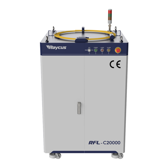
(mm) Weight (kg) Air conditioning included <700 Operating Ambient 10~40 Temperature (°C) Humidity (%) <90 -10~60 Storage Temperature (°C) Cooling Method Water cooling Installation 3.1. Dimensions The main body dimensions of RFL-C20000M-CE continuous fiber laser are shown in Figure 2. - Page 11 Wuhan Raycus Fiber Laser Technologies Co., Ltd. User Guide of RFL-C20000M-CE Figure 2-a Front and rear view of the laser.
- Page 12 Figure 2The dimensions of RFL-C20000M-CE continuous fiber laser The structure size of RFL-C20000M-CE laser is 960x1530x1160mm (width×height×depth; including casters and rings, without warning light); RFL-C20000M-CE laser weighs less than 700kg. The RFL-C20000M-CE continuous fiber laser uses the RFL-QP output optical cable, and the external dimensions of the output optical cable head are shown in Figure 3.
-
Page 13: Installation Rule
Wuhan Raycus Fiber Laser Technologies Co., Ltd. User Guide of RFL-C20000M-CE must be cleaned. It is forbidden to disassemble the output lens by anyone other than staff in Raycus, otherwise the warranty will be invalidated. 3.2. Installation rule a) Place the laser horizontally in a suitable position and fix it as necessary;... - Page 14 Wuhan Raycus Fiber Laser Technologies Co., Ltd. User Guide of RFL-C20000M-CE Figure 4 Laser top lifting ring and bottom level adjustment caster. CAUTION: All the cables can only be connected when power supply is off. Hot plug may damage the device.
-
Page 15: Protective End Cap Of Output Cable And Using Description
Wuhan Raycus Fiber Laser Technologies Co., Ltd. User Guide of RFL-C20000M-CE 3.3. Protective end cap of output cable and using description 3.3.1 Types of protective end caps and factory status For multi-module high-power fiber lasers, the output cable type used is QBH/QD/QP output optical cable. -
Page 16: Pre-Installation Cleaning Instructions For Output Cables
Wuhan Raycus Fiber Laser Technologies Co., Ltd. User Guide of RFL-C20000M-CE 3.3.2 Pre-installation cleaning instructions for output cables Preparation tools Cleaning agent: absolute ethanol, or isopropyl alcohol. Cleaning tools: cleaning cotton swabs, dust-free paper, compressed air bottles, etc. Steps clean workbench should be turned on for at least 5 minutes , and the output optical cable... - Page 17 Wuhan Raycus Fiber Laser Technologies Co., Ltd. User Guide of RFL-C20000M-CE Figure 8 Output optical cable with white dust cover removed e)Use a cotton swab and anhydrous ethanol to clean the metal casing of the optical cable, then remove the end cap (with window) attached to the optical cable, and place it on a clean paper .
-
Page 18: Cooling Requirements
Wuhan Raycus Fiber Laser Technologies Co., Ltd. User Guide of RFL-C20000M-CE optic cable output head to the cutting head (or welding head) with the B- type end cap installed. This operation needs to ensure the cleanliness of the inner and outer surfaces of the cutting head (or welding head) connector. - Page 19 If ambient temperature is below - 10℃, the chiller with both heating and cooling functions must be used, and keep it in full-time operation; f)For the connection of cooling water and normal temperature water circuits,please use Raycus supporting water pipes.If the water pipes are self-distributed,please do not increase the length of the water pipes and change the inner diameter of the water pipes;...
- Page 20 Wuhan Raycus Fiber Laser Technologies Co., Ltd. User Guide of RFL-C20000M-CE Water cooling requirements for output optical cables: a) Water flow requirements: QP output cable water flow is greater than 3.0L/min; b)Water cooling pressure: 0.4~0.6Mpa at the water inlet; c) Water inlet and outlet connector type: M6 to ϕ8 quick-tightening connector;...
-
Page 21: Using The Product
Wuhan Raycus Fiber Laser Technologies Co., Ltd. User Guide of RFL-C20000M-CE Using the Product △ Please login to the official website of Raycus to download the new PC software and the PC software user manual. Website: http://www.raycuslaser.com 4.1. Front Panel Figure 12 shows the front panel. -
Page 22: Rear Panel
Wuhan Raycus Fiber Laser Technologies Co., Ltd. User Guide of RFL-C20000M-CE ALARM INTERLCOK alarm indication, the ALARM indicator lights up during the power-on self-check on the control panel. After the self-inspection is completed, all INTERLOCK interfaces are normally closed, and the ALARM indicator is off. During the operation of the laser, if any INTERLOCK is disconnected and the laser preparation is not completed, the indicator light will be on. -
Page 23: Power Connection
Wuhan Raycus Fiber Laser Technologies Co., Ltd. User Guide of RFL-C20000M-CE -INTERFACE:This interface provides all control signals, including: RS232 communication, laser on/off control, laser remote control mode selection, analog control, modulation signal, Interlock interface, etc.Refer to Table 4 for the definition of control lines. This socket comes with a protective cover and a lock. -
Page 24: Control Interface Definition
Wuhan Raycus Fiber Laser Technologies Co., Ltd. User Guide of RFL-C20000M-CE The standard length of RFL- C20000M-CE provided by Raycus is 15 meters. 4.4. Control interface definition This type of laser does not provide a control signal line, only a control signal connector. The appearance of the joint is shown in Figure 14. -
Page 25: Hardwiring Xp1
Wuhan Raycus Fiber Laser Technologies Co., Ltd. User Guide of RFL-C20000M-CE OUT(FET S pole) Laser output indication,MOS pipe D, S output; current<0.1A, V <30V, passive signal. OUT(FET D pole) Connect the negative pole of the external laser-emitting indicator, current< Connect the negative pole of the external power-on indicator, current<... - Page 26 Wuhan Raycus Fiber Laser Technologies Co., Ltd. User Guide of RFL-C20000M-CE Table 7XP1 Hardwire interface definitions No. XP1 Interface requirements type description Pin definition Laser request Input Laser request signal, only after this bit is valid will the laser receive other XP1 hard-wired...
- Page 27 Wuhan Raycus Fiber Laser Technologies Co., Ltd. User Guide of RFL-C20000M-CE C3 is the lowest bit, C6 is the highest bit: 0000-close all optical gate channels; 0001-open channel 1; Selecttheoptic Input C3~C6 algate 0010-open channel 2; signal 0011-open channel 3.
-
Page 28: Rs232 Xp3 Interface
The 9-pin serial interface is used for the communication between the laser and the upper computer. It can be used to communicate with the upper computer of Raycus Company or the software of the upper computer which integrates the communication protocol of Raycus. The definitions are as follows. -
Page 29: Analog Interface Xp4
4.5. Introduction to Safety Interlock Raycus‟ product is designed with a safe interlocking loop, which is a two-channel system with output monitoring and manual reset. When the safety interlocking circuit is open, the safety circuit will disconnect the working power of the optical module, that is, the main power supply of the optical module. -
Page 30: Schematic Diagram Of The Internal Electrical Circuit Of The Laser
Wuhan Raycus Fiber Laser Technologies Co., Ltd. User Guide of RFL-C20000M-CE start until the other channel is open, and then the two channels are closed before the laser main power supply can be started. If the interlock is closed (the stop button is also released) and there is no error alarm, press the start (LASER) button to start the main power supply, and the „main power has been started‟... -
Page 31: Start Operation Sequence
Figure 15 Schematic diagram of the internal electrical circuit of the laser Note: RFL-C20000M-CE laser power control part contactors K1 and K2 are used in parallel with 2 50A and 1 32A contactors, and 6 signal terminals are used in series. -
Page 32: Control Mode Selection
Control Mode Selection The Raycus high-power CW laser has two control modes: namely ON mode and REM mode. Users can select the mode to be entered through the key on the front panel. - Page 33 Wuhan Raycus Fiber Laser Technologies Co., Ltd. User Guide of RFL-C20000M-CE XP1-A1 laser request is high XP4-1/2 pin XP1-A2 laser emission XP1-A1/A5 is Enable⑧ Enable⑨ close⑦ pressure enable is high high level XP2- 1/2 input MOD singal XP1-A1 laser request is...
-
Page 34: On Mode
MOD+, MOD- in the XP2 port; if the emission external control is not enabled, thelaser emission or shutdown are determined by the emit button in the Raycus Laser Control System. Also, you can send “EMON” command to turn laser emission on, and send “EMOFF”... -
Page 35: Guide Laser (Red Guide Beam) Control
5.4. Guide Laser (Red Guide Beam) Control In “ON” mode guide laser can only be turned on/off by using Raycus Laser Control System, or bysending command of “ABN” (on) / “ABF” (off). The red light module inside the laser works through communication, so there is a time delay of at least 10ms for the opening and closing of red light;... -
Page 36: Emission External Control
10ms when the red light is turned on and off. When the red light is on, the laser cannot be set to Ready. Only after the red light is turned off the laser can be set to “Ready”. (This limit can be changed, please contact Raycus Engineer). 5.6.4 Programming Mode When A1 of XP1 is set high and A8-A14 is not 0, the laser is in “Programming Mode”. -
Page 37: Laser Wiring Diagram And Operation Steps
Wuhan Raycus Fiber Laser Technologies Co., Ltd. User Guide of RFL-C20000M-CE 6. Laser Wiring Diagram and Operation Steps 6.1. Internal control in ON Mode Raycus Laser Serial port line XP3(Serial Interface) Ethernet cable XP5(Ethernet Interface) Interlock1 Interlock2 (Security Interface) AC POWER... -
Page 38: Laser Operating In External Control Mode
Wuhan Raycus Fiber Laser Technologies Co., Ltd. User Guide of RFL-C20000M-CE 6.2. Laser Operating in External Control Mode Raycus Laser Serial port line XP3(Serial Interface) XP5(Ethernet Interface) Ethernet cable Peripheral MOD+ MOD - Equipment Interlock1 Interlock2 (Security Interface) AC POWER... -
Page 39: In On Mode, The Laser Emission Power Is Externally Controlled By Analog Signal
Wuhan Raycus Fiber Laser Technologies Co., Ltd. User Guide of RFL-C20000M-CE 6.3. In ON Mode, the Laser Emission Power is Externally Controlled by Analog Signal Raycus Laser Serial port line XP3(Serial Interface) XP5(Ethernet Interface) Ethernet cable Analog value(0~ 10V) XP4(Analog Interface) -
Page 40: Laser Operating In External Control Programming Mode
MOD signal. NOTE: The high-level time of MOD must be greater than the program running time. If MOD gives a falling edge in advance, the Raycus Laser Control System will display that the laser program is abnormally terminated. -
Page 41: Set The Power Analog Quantity In Rem Mode To Control The Laser Emission
Wuhan Raycus Fiber Laser Technologies Co., Ltd. User Guide of RFL-C20000M-CE 6.5. Set the Power Analog Quantity in REM Mode to Control the Laser Emission Raycus Laser A1(Laser Request) A2(Laser EN) XP1(Hardwiring) A6(Analog EN) A16(COM) Peripheral Analog value(0~ 10V) Equipment... -
Page 42: Power Communication Setting In Rem
Wuhan Raycus Fiber Laser Technologies Co., Ltd. User Guide of RFL-C20000M-CE Figure 21 Timing diagram 6.6. Power Communication Setting in REM Raycus Laser A1(Laser Request) A2(Laser EN) XP1(Hardwiring) Peripheral A16(COM) Equipment MOD+ MOD - Power ON Interlock1 (Security Interface) Interlock2... -
Page 43: Programming Mode In Rem Mode
24V, and the main power is turned on (users can also directly press the “LASER” button, or the host computer software clicks the main power “ON”) g)Waiting for “Ready” h)The Raycus Laser Control System sets the power, XP1-A2 is connected to 24V, and the control board card outputs MOD signal 6.7. -
Page 44: Rs232 And Internet Communication Command
Wuhan Raycus Fiber Laser Technologies Co., Ltd. User Guide of RFL-C20000M-CE Operations Steps: a) Turn the knob switch on the rear panel to“ON” b)Turn the key switch to“REM” c) Short-circuit pin 8/9 on XP2 d)XP1-A1 connects to 24V e) Connect XP1-A5 to 24V and turn on the guide laser; after checking the optics, connect XP1-A5 to... -
Page 45: Laser Communication Protocol (Network Port & Serial Port)
Wuhan Raycus Fiber Laser Technologies Co., Ltd. User Guide of RFL-C20000M-CE 7.2. Laser Communication Protocol (Network Port & Serial Port) All commands and return values in this Agreement are composed of ASCII characters. Note the following points when entering: a) Commands generally consist of three or four letters, sometimes with additional values. - Page 46 Wuhan Raycus Fiber Laser Technologies Co., Ltd. User Guide of RFL-C20000M-CE Send: „SPW 100\r‟ Return: „SPW:100\r‟ (Set pulse widthas 100ms) Other return values: „ERR: input Err\r‟ (Input pulse width <0.0001) Set Pulse Width „ERR: Out of Range\r‟ (Over maximum pulse width)...
- Page 47 Wuhan Raycus Fiber Laser Technologies Co., Ltd. User Guide of RFL-C20000M-CE Send: „SDT 50\r‟ Set Down Time (ms) Return: „SDT:50\r‟ Send: „RUT \r‟ Read Up Time (ms) Return: „RUT:50\r‟ Send: „RDT \r‟ Read Down Time(ms) Return: „RDT:50\r‟ Send: „PSRT 1\r‟...
- Page 48 Wuhan Raycus Fiber Laser Technologies Co., Ltd. User Guide of RFL-C20000M-CE Power Correction Mode=on normal Bit 6 Sub-controling communication abnormal Normal Bit 7 Sub-modual abnormal Guide red light=off Bit 8 Guide red light=on The laser is not ready Bit 9...
-
Page 49: Pc Software Instructions
Wuhan Raycus Fiber Laser Technologies Co., Ltd. User Guide of RFL-C20000M-CE Wave mode off Bit 22 Wave mode on Surge protector normal Bit 23 Serge protector failure normal Bit 24 Low temperature fault normal Bit 25 Humidity alarm normal Bit 26... -
Page 50: Multi-Laser Control Area
Wuhan Raycus Fiber Laser Technologies Co., Ltd. User Guide of RFL-C20000M-CE Figure 25PC software display main interface 8.2. Multi-laser control area Multi-laser control area is as Figure 26 Figure 26Multi-laser control area interface... -
Page 51: Add/Delete Laser
Wuhan Raycus Fiber Laser Technologies Co., Ltd. User Guide of RFL-C20000M-CE Select IP address of corresponding laser, then double click. PC software will take communication with selected laser.After the communication established, the lower left status display shows that the network connection is ok, as Figure 27. -
Page 52: Modifylaserip
Wuhan Raycus Fiber Laser Technologies Co., Ltd. User Guide of RFL-C20000M-CE 8.2.2 ModifylaserIP After the laser connection has established, select the IP address of current laser and right-click to set it up as Figure 29. Figure 29Modify the IP address of laser 8.3. -
Page 53: Laser's Cumulative Operating Time Display Area
Wuhan Raycus Fiber Laser Technologies Co., Ltd. User Guide of RFL-C20000M-CE Figure 30A diagram of the laser's main display area Table 13The laser main display content and meaning Display Meaning Output power current setting percentage of power in realtime Output power Average laser output power in realtime(W)... - Page 54 Wuhan Raycus Fiber Laser Technologies Co., Ltd. User Guide of RFL-C20000M-CE Figure 32A diagram of the laser's working status display area Table 14The laser main display area clarification Display Content explanation Red: emergency stop button on front panel is pressed...
-
Page 55: Laser Power-Up, Mode Selection, Light-Out Control Area
Wuhan Raycus Fiber Laser Technologies Co., Ltd. User Guide of RFL-C20000M-CE 8.3.3 Laser power-up, mode selection, light-out control area Laser power-up, mode selection, light out control display area is as in Figure 33, the display content is as in Table 15. -
Page 56: Power Slow Rise&Down Parametersettingarea
Wuhan Raycus Fiber Laser Technologies Co., Ltd. User Guide of RFL-C20000M-CE Figure 34Laser programming mode test area display interface 8.3.5 Power slow rise&down parametersettingarea The interface of the laser power slow rise & fall parameter setting area is as Figure 35. Click „read parameter‟... -
Page 57: Laserparameterdisplayarea
Wuhan Raycus Fiber Laser Technologies Co., Ltd. User Guide of RFL-C20000M-CE 8.4. Laserparameterdisplayarea The display interface for laser parameter display area is as Figure 37. The module status is used to shield the faulty module, the green light indicates the number of modules installed inside the current laser, and the check box indicates the module that is actually running in the current laser. - Page 58 Wuhan Raycus Fiber Laser Technologies Co., Ltd. User Guide of RFL-C20000M-CE Figure 39Laser operating mode selects the display area interface Table 16Laser operating mode and explanation Mode explanation Mode selection Monitor A concise software interface, which can monitor basic status information...
-
Page 59: Languagedisplays Laser's All Status And Parameters For Diagnosis Purposes
Wuhan Raycus Fiber Laser Technologies Co., Ltd. User Guide of RFL-C20000M-CE 8.7. LanguageDisplays laser’s all status and parameters for diagnosis purposes Laser‟s language selection interface is as figure 40. User can choose between Chinese simplified and English by click „setting language‟. Setting effective after PC software restarted. -
Page 60: Authorization In Authorization Mode
Wuhan Raycus Fiber Laser Technologies Co., Ltd. User Guide of RFL-C20000M-CE Figure 41The authorization settings operating interface in user mode 8.8.2 Authorization in authorization mode The authorization settings in laser authorization mode are as Figure 42. This interface allows the customer to lock and unlock the machine and can also be used as an authorization code generator. -
Page 61: About
Wuhan Raycus Fiber Laser Technologies Co., Ltd. User Guide of RFL-C20000M-CE Figure 42 Authorization settings operating interface in authorization mode 8.9. About Laser relevant information such as date of manufacture, model, serial number, controling serial number, token version number, system information and other information can be queried in the PC... -
Page 62: Xp1 Interface Status Indication (In Diagnostic Mode)
Wuhan Raycus Fiber Laser Technologies Co., Ltd. User Guide of RFL-C20000M-CE Figure 43 Laser relevant information query interface 8.10. XP1 interface status indication (in diagnostic mode) The laser interface status indicator interface is as Figure 44. It is convenient to view the interface... -
Page 63: Log (In Diagnostic Mode)
Wuhan Raycus Fiber Laser Technologies Co., Ltd. User Guide of RFL-C20000M-CE Figure 44 The interface status in diagnostic mode 8.11. Log (in diagnostic mode) Laser‟s working log interface is as Figure 45. User can query work log by entering the time to query and click on the „search‟... -
Page 64: Download Log
Wuhan Raycus Fiber Laser Technologies Co., Ltd. User Guide of RFL-C20000M-CE 8.11.1 Download log Log download interface is as Figure 46. Figure 46 Log download interface 8.11.2 Downloadrecord of historicalfault Historical fault record download interface is as Figure 47. Figure 47Historical fault record download interface... -
Page 65: Downloaded File Address
8.12. Module parameters (in diagnostic mode) Laser module parameter query interface is as Figure 49. The interface is for the parameter query in diagnostic mode from which Raycus technicians can analyze the cause of laser anomalies. Figure 49Module parameters query interface in diagnostic mode 8.13. -
Page 66: View The Number Of Wave Bars Inside The Current Laser
Wuhan Raycus Fiber Laser Technologies Co., Ltd. User Guide of RFL-C20000M-CE Figure 50The programming interface in programming editing mode 8.13.1 View the number of wave bars inside the current laser Operating interfaces of view the number of wave bar stored inside the current laser is as Figure 51. -
Page 67: Check Waveform Content
Wuhan Raycus Fiber Laser Technologies Co., Ltd. User Guide of RFL-C20000M-CE 8.13.2 Check waveform content To check the programming contents in the current laser programming mode is as Figure 52. The program automatically lists the original programmings by click the programming number that needs to be checked. -
Page 68: Editwaveform
Wuhan Raycus Fiber Laser Technologies Co., Ltd. User Guide of RFL-C20000M-CE 8.13.4 Editwaveform Programming editing when the laser is working in programming mode is as Figure 54. Step 1:left click the pre-edited programming number. Step 2:select the command under the command type, click „Add‟. - Page 69 Wuhan Raycus Fiber Laser Technologies Co., Ltd. User Guide of RFL-C20000M-CE b)add command type c)save command...
-
Page 70: Command Explanation
Wuhan Raycus Fiber Laser Technologies Co., Ltd. User Guide of RFL-C20000M-CE d)type the command code into laser e)check effectiveness of instruction Figure 54A diagram of the programming editing operation in programming mode 8.13.5 Command explanation Command meaning in laser working status isas Table 17. - Page 71 Wuhan Raycus Fiber Laser Technologies Co., Ltd. User Guide of RFL-C20000M-CE Table 17command meaning in laser working status Code (1 Byte) Parameter1(2 bytes) Parameter 2(4 bytes) Note The program end command. the last none none Stop command must be this command.
-
Page 72: Warranty, Repair And Return
Raycus has the right to selectively repair or replace any product that has a material or technical problem during the warranty period. All products repaired or replaced during the warranty period only provide free warranty services for products with special problems. -
Page 73: Scrap Requirements
Raycus reserve the right to make changes in design or constructions of any of our products at anytime without incurring any obligation to make changes or install the same on units previously purchased.
Need help?
Do you have a question about the RFL-C20000M-CE and is the answer not in the manual?
Questions and answers