Table of Contents
Advertisement
Quick Links
Advertisement
Table of Contents

Subscribe to Our Youtube Channel
Related Manuals for AccuEnergy AcuLink 810

Summary of Contents for AccuEnergy AcuLink 810
- Page 1 AcuLink 810 Data Acquisition Server User's Manual...
- Page 2 Copyright © 2020 V1.08 This manual may not be altered or reproduced in whole or in part by any means without the expressed written consent of Accuenergy. V: 1.08 Revised: May 2020 www.accuenergy.com...
- Page 3 Accuenergy shall not be responsible or liable for any damages or injuries caused by improper meter installation and/or operation.
-
Page 4: Table Of Contents
5.3 RS485 LEDs ........................13 Chapter 6: Initializing the AcuLink 810 ..............14 6.1 Accessing the AcuLink 810 Web Interface ...............14 6.1.1 Method 1 - Direct Connection via Ethernet ..........14 6.1.2 Method 2 - Using WIFI to connect to the Meters Web Interface ....18 6.2 Dashboard ........................21... - Page 5 9.2 AcuMesh ........................55 9.2.1 Local Configuration ..................56 9.2.2 Scan & Remote Configuration ................57 9.2.3 AcuMesh Diagnostics ..................60 9.2.4 Adding AcuMesh Device .................61 9.2.5 Search Modbus Device ...................63 9.3 Modbus Polling ......................65 9.4 BACnet .........................67 V: 1.08 Revised: May 2020 www.accuenergy.com...
- Page 6 Chapter 12: Alarms ....................91 12.1 Device Alarm ......................91 12.2 Alarm Log ........................93 12.3 Email Alarm Notifications ..................94 Chapter 13: Data Logging ..................96 13.1 Data Loggers ......................96 13.1.1 Rapid Logger ....................98 13.2 Post Channels ......................99 V: 1.08 Revised: May 2020 www.accuenergy.com...
- Page 7 Chapter 14: Network Diagnostics ..............108 Chapter 15: Maintenance ................113 15.1 System Status ......................113 15.2 Event Log .........................113 Chapter 16: Firmware Update ................. 115 16.1 Manual Update .......................115 16.2 Remote Update .......................118 Chapter 17: Reset Button ................. 121 V: 1.08 Revised: May 2020 www.accuenergy.com...
-
Page 8: Chapter 1: Overview
AcuLink 810 Data Aquisition Server Chapter 1: Overview The AcuLink 810 is an intelligent data acquisition server and gateway that allows users to collect data from all Accuenergy meters, sensors and other third party devices. The AcuLink collects and logs time-stamped data from connected downstream devices (se- rial or Ethernet), and is able to store this data locally in non volatile memory. -
Page 9: Inputs
AcuLink 810 Data Aquisition Server • WIFI: 802.11 b/g/n, 2.4GHz • USB: USB expansion port, USB 2.0 Host 2.4 Inputs • RS485 Port: RS485 Modbus, supports up to 32 external devices (expandable) • Baud Rate: 9600-115200 bps • USB Port: Modbus via RS485-USB converter, supports up to 32 external devices •... -
Page 10: Chapter 3: Appearance And Dimensions
AcuLink 810 Data Aquisition Server Chapter 3: Appearance and Dimensions Physical Size: 6.3" x 3.5" x 1.23" (159.9mm x 90mm x 32.2mm) 90mm (3.5”) V: 1.08 Revised: May 2020 www.accuenergy.com... -
Page 11: Chapter 4: Installation
4.1 Installation Checklist The following materials are required for the AcuLink 810 installation: • AcuLink 810 Data Acquisition Server • Ethernet Cat 5 Cable (Required for LAN or direct computer to AcuLink 810 connection) • Power Supply (24V) • WIFI Antenna 4.1.1 Optional Hardware:... -
Page 12: Installation Safety Requirements And Considerations
• Pollution Degree: 2 4.2 Powering the unit • The power supply of the AcuLink 810 is rated for 24Vdc. D A T A A C Q U S I T I O N S E R V E R... -
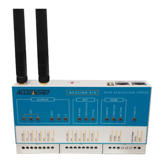
Page 13: Chapter 5: Led Description
Chapter 5: LED Description Chapter 5: LED Description There are a total of 13 LEDs on the AcuLink 810 data acquisition server and each represent different functions pertaining to the unit. D A T A A C Q U S I T I O N S E R V E R... -
Page 14: Wifi Leds
AcuLink 810 Data Aquisition Server • ASSOC • Indicates that the transceiver is powered on or it is communicating. The Red LED is ON when powered, and briefly ON or flashing during RF transmission. • RX • Indicates that the transceiver is receiving data. -
Page 15: Rs485 Leds
• When ON indicates that some of the devices in the RS485 network are offline and is represented by a yellow LED • NO COMM • When ON indicates that all RS485 devices in the RS485 network are offline and is rep- resented by a red LED V: 1.08 Revised: May 2020 www.accuenergy.com... -
Page 16: Chapter 6: Initializing The Aculink 810
AcuLink 810 Data Aquisition Server Chapter 6: Initializing the AcuLink 810 The AcuLink 810 has a web interface that users can access to configure the gateway set- tings and view device data. The AcuLink 810 gateway has two Ethernet ports and also sup- ports communication via WIFI. - Page 17 Chapter 6: Initializing the AcuLink 810 Next in order to access the web interface, the computers IP address must be config- ured within the same subnet as the AcuLink Ethernet 1 IP address. The Ethernet 1 port has a default IP address of 192.168.8.101.
- Page 18 AcuLink 810 Data Aquisition Server • On the left panel of the screen, select Change adapter settings . • Double click on Ethernet , or right click on Ethernet and select Properties . • The following page will open, click on Properties .
- Page 19 Select the option Use the following IP address : and change the IP address of the comput- • er. The AcuLink 810 Ethernet 1 address is 192.168.8.101, the computers IP will need to be within the same subnet. The IP of the computer can be 192.168.8.xxx, where xxx can be any number ranging from 1-254.
-
Page 20: Method 2 - Using Wifi To Connect To The Meters Web Interface
AcuLink 810 Data Aquisition Server • Once all settings are complete click on OK to confirm the network changes. • Then open up an internet browser and type in the AcuLink 810 IP address of 192.168.8.101 , a login screen will be prompted. - Page 21 D A T A A C Q U S I T I O N S E R V E R By default the AcuLink 810 has its WIFI mode set as AP (Access Point) mode, where the AcuLink 810 acts as a wireless access point allowing other wireless devices to connect and access the gateway.
- Page 22 AcuLink 810 Data Aquisition Server • Once connected to the gateways wireless network, open up an internet browser and enter in the IP address 192.168.100.1 . The web server login screen will be prompted. • There are two Access Level, Viewer and Admin.
-
Page 23: Dashboard
Chapter 6: Initializing the AcuLink 810 6.2 Dashboard When logged in the to the AcuLink 810 web interface, users are directed to the Dashboard. The dashboard provides the user with a summary of all the Offline Devices as well as the Devices in Alarm. Under the alarms section of the dashboard the interface includes the Up Since time, which lets the user know the time the 810 was powered on or rebooted. -
Page 24: About Page
AcuLink 810 Data Aquisition Server 6.2.1 About Page Users can check the AcuLink 810 Device Information on the About page located on the top right corner of the dashboard. From the About page users are provided with an overview of the AcuLink 810 model number, serial number, Hardware and Firmware versions, and the Ethernet/WIFI MAX addresses. -
Page 25: Chapter 7: Device Templates
Modbus parameters. In order for the AcuLink 810 to read device data using either Modbus or BACnet protocols a device template will first need to be installed or created. Within the AcuLink 810 web interface, users can create, modify and convert their own templates from different formats (csv, EPICS, etc). -
Page 26: Import Template
AcuLink 810 Data Aquisition Server Customized Templates If there are customized templates on the AcuLink 810 users have the following action but- tons available. The icons have the following meaning: Actions The first icon allows users to download the .def template file. -
Page 27: New Template
Read Discrete Input, Read Coils, read Input Registers) • Enter in the starting address of the register block, this address must be in hexadecimal. • Enter the count, i.e. the number of registers in this block. V: 1.08 Revised: May 2020 www.accuenergy.com... - Page 28 AcuLink 810 Data Aquisition Server Once all register block information is configured correctly click on Save Block. The saved block will then appear in the Block Table at the bottom portion of the web page. In the Block Table users have the option to edit, delete or view the details of the register block created.
- Page 29 Block Table below under the Detail tab. Un- der the detail tab users can edit the existing parameter by selecting the Edit button, and can delete the existing parameter by selecting the Delete button. V: 1.08 Revised: May 2020 www.accuenergy.com...
- Page 30 AcuLink 810 Data Aquisition Server Once Users have added all required parameters to the Modbus Template click on Next. 4. Save The last step is saving the device template. Users can review the Block Table and modify any parameters before saving the template. They can also click on Prev button to go back and alter any blocks or parameters as needed..
-
Page 31: Typical Energy Meter Template
Once a block is created click on Save Block , users can create multiple blocks for the device template. All created blocks will appear in the block table located further down the page. V: 1.08 Revised: May 2020 www.accuenergy.com... - Page 32 AcuLink 810 Data Aquisition Server 3. Parameter Table The parameter table has all the parameters that are supported on our cloud based software. Users can find and locate the same parameters within the table that are supported on their third party device and configure it to their template by clicking on the Edit button next to that parameter.
-
Page 33: Creating Template From Csv
7.1.4 Creating Template from CSV The AcuLink 810 supports a CSV to Modbus template converter directly from its web inter- face. To access this converter click on the Convert From CSV File tab on the Modbus Tem- plate page. - Page 34 AcuLink 810 Data Aquisition Server The sample CSV file: V: 1.08 Revised: May 2020 www.accuenergy.com...
-
Page 35: Bacnet Template
7.2 BACnet Template BACnet Templates are used in the AcuLink 810 to correctly read the metering data from Accuenergy and third party BACnet devices. Before a device can be added to the gateway a BACnet template for the device must first be uploaded and installed onto the unit. -
Page 36: Import Template
Alternatively users can download a BACnet template from our remote server by clicking on the Check button. A template can be installed directly from our server to the AcuLink 810. NOTE: If users are updating or editing an existing template the Data log and alarm monitor- ing configurations will be lost after updating an existing device template. - Page 37 Once the name, version and EPICS file has been uploaded users can click on Upload . Users will be able to configure and specify which parameter they want to include in the BACnet template, once the parameters are configured click on Save at the bottom of the page. V: 1.08 Revised: May 2020 www.accuenergy.com...
- Page 38 AcuLink 810 Data Aquisition Server Users will be redirected to the Installed tab in the BACnet Template page where the newly converted template file will be seen under the Customized templates located at the bottom of the page. V: 1.08 Revised: May 2020...
-
Page 39: Chapter 8: System Settings
Status tab. Users can configure all Ethernet (ports 1 & 2), WiFi, DNS, and RSTP configura- tions from this page. 8.1.1 Ethernet There are two Ethernet ports on the AcuLink 810, by default Ethernet port 1 has a static IP where as Ethernet port 2 is configured for DHCP. Default Ethernet port 1 settings: •... -
Page 40: Wifi
NOTE: When using WiFi ensure that the provided antenna is installed on the AcuLink 810 unit. • Access Point Mode - Is the default WiFi configuration for AcuLink 810, where the gateway will act as a wireless access point and will allow other wireless devices to connect and access the AcuLink 810. -
Page 41: Http Proxy
Chapter 8: System Settings • Station Mode: The AcuLink 810 will behave like a wireless client and bridge to another wireless network that is available. • In Station mode, users can select the Wireless network to connect to in the SSID drop down menu. -
Page 42: Rstp
The RSTP protocol allows users to create an Ethernet daisy chain using the two Ethernet ports of the AcuLink 810. The 810 can be daisy chained to a network switch/router, other AcuLink 810, and other devices supporting the RSTP protocol. -
Page 43: Default Routing Interface
Chapter 8: System Settings 8.1.5 Default Routing Interface The AcuLink 810 supports a routing default interface setting which allows users to configure which port to use for primary routing to external networks. Since there are multiple ways the user can connect such as Ethernet1/2, WIFI, RSTP, this setting will establish which one is used for the main routing. -
Page 44: Time & Date
If users to not want to sync the device time to an NTP server they can disable the NTP setting and configure the time and date manually. • Time Sync: Users can force the time to update to the NTP on the AcuLink 810 by clicking the Sync button. -
Page 45: Remote Access
Chapter 8: System Settings 8.3 Remote Access The AcuLink 810 supports a remote access function that allows users to access the AcuLink 810 web interface. By accessing the interface remotely users will have full functionality as well as access to all gateway settings and device readings. This feature allows users to access the AcuLink 810 web interface through an HTTPS web server easily through a URL without any network port forwarding. - Page 46 AcuLink 810 Data Aquisition Server When first enabling remote access and registering the status will be displayed as offline, us- ers may click on the Refresh Status button to see the status turn to online. Once the status is online the remote access user interface can be accessed by clicking on the remote access url or by using the copy button and pasting the url into a new tab on the internet browser.
-
Page 47: User Management
NOTE: Only users logged in with Admin access level can change the password for either Admin or Viewer access levels. For the viewer access level the default password is view . For the admin access level the default password is admin . V: 1.08 Revised: May 2020 www.accuenergy.com... -
Page 48: Chapter 9: Protocols
AcuLink with any Accuenergy or third party device. If connecting multiple devices or 'daisy-chaining' the devices together, ensure that a unique device address (Mod- bus Slave ID) is configured for each RS485 device. The AcuLink 810 can support up to 32 external RS485 devices. -
Page 49: Usb Devices
Chapter 9: Protocols 9.1.2 USB Devices The AcuLink 810 has a USB port that allows for an additional 32 Modbus RTU devices. Users can connect the additional using an RS485 to USB converter cable. Acuvim L Series Meter RS485 to USB... - Page 50 Parity: Select the parity of the device from the drop-down list Stop Bit: Select the number of Stop Bits Request Timeout: Select a timeout period for the AcuLink 810 to wait for a response from the device, the range is 1-60 seconds, default for Modbus RTU is 0.5.
- Page 51 NOTE: After adding a new device to the gateway it may take up to 3-4 minutes for the status to show 'ON'. If after 3-4 minutes the device is showing an 'OFF' status, double-check the configuration settings to ensure everything is set correctly. V: 1.08 Revised: May 2020 www.accuenergy.com...
- Page 52 AcuLink 810 Data Aquisition Server If users need to change the configuration of an added device, they can simply click on the device and then select the Configuration . From this page users can re-configure the device name, port type, baud rate, parity, etc.
-
Page 53: Tcp Devices
Chapter 9: Protocols 9.1.4 TCP Devices The AcuLink 810 can support up to 100 Modbus TCP devices where the devices will need to be on the same network as the gateway. Netwiork Switch Acuvim II Series Meter Ethernet Cable Ethernet Cable D A T A A C Q U S I T I O N S E R V E R 9.1.5 Adding Modbus TCP Device... - Page 54 AcuLink 810 Data Aquisition Server Protocol: Select TCP as the protocol IP Address: Enter the IP address of the device Port: Enter the Modbus port of the device Modbus ID: Enter the Modbus address of the device Request Timeout: Enter the timeout setting, default for TCP is 3 seconds Click Save once all settings are entered correctly.
- Page 55 If users need to change the configuration of an added device, they can simply click on the device and then select the Configuration . From this page users can re-configure the device name, port type, IP address, Modbus ID, etc. V: 1.08 Revised: May 2020 www.accuenergy.com...
-
Page 56: Modbus Gateway Function
AcuLink 810 Data Aquisition Server 9.1.6 Modbus Gateway Function The AcuLink 810 supports a Modbus Gateway Function, where users can add a Modbus RTU device and use it as a gateway. Users must choose the device template as Modbus Gateway Function Only . -
Page 57: Acumesh
Chapter 9: Protocols 9.2 AcuMesh Certain models of the AcuLink 810 supports AcuMesh which allows for a wireless RS485 net- work. The gateway has a built in AcuMesh into its hardware which allows the 810 to connect wirelessly via RS485 to gather information from both Accuenergy and third party Modbus devices using AcuMesh transceivers/modules. -
Page 58: Local Configuration
• The AcuLink-900 (900 MHz) is mainly used in North and South America, Oceania, and also certain parts of Asia. NOTE: The AcuLink 810-X model does not support AcuMesh To configure the AcuMesh settings on the AcuLink 810 click on the Protocols tab and select AcuMesh . 9.2.1 Local Configuration In order for the AcuLink to add other AcuMesh devices, the local AcuMesh settings must be configured first. -
Page 59: Scan & Remote Configuration
ID that will be scanned, the Encryption, and the Channel Mask that is being used. The network Hops configuration is the number of times the mesh network will be scanned, the range is from 1-7 network hops. V: 1.08 Revised: May 2020 www.accuenergy.com... - Page 60 AcuLink 810 Data Aquisition Server Click on Start Scan to search for remote AcuMesh transceivers. All devices found during the scan will have the AcuMesh Node name, the number of network hops that the Mesh device was discovered in, and the MAC address displayed on the inter- face.
- Page 61 Advanced Options: Baud Rate: Select the baud rate of the device, range is from 9600-115200 Parity: Select the parity of the device from the drop down list Stop Bit: Select the number of Stop Bits V: 1.08 Revised: May 2020 www.accuenergy.com...
-
Page 62: Acumesh Diagnostics
The AcuMesh diagnostics page allows the user to troubleshoot the AcuMesh connection from the AcuLink 810 to the remote AcuMesh transceivers. The test sends packets at a certain interval and tests whether the AcuLink 810 gets a response from the slave AcuMesh transcievers. -
Page 63: Adding Acumesh Device
AcuMesh MAC Address: Select the AcuMesh MAC address of the remote mesh transceiver of the Modbus device. Users can click on Go to AcuMesh Scan & Configuration page to discover remote Mesh transceivers. Request Timeout: The default timeout setting for an AcuMesh device is 10 seconds. V: 1.08 Revised: May 2020 www.accuenergy.com... - Page 64 AcuLink 810 Data Aquisition Server After the device is added, it can be found in the Modbus Devices pages. A device that is successfully connected and communicating with the gateway will have display a green ON status under the status column. Whiles a device that is offline will display a red OFF warning symbol under the status menu.
-
Page 65: Search Modbus Device
Chapter 9: Protocols 9.2.5 Search Modbus Device There is a search device function in the AcuLink 810 gateway that allows the user to search for all Modbus devices. The search criteria is based on the template model, Modbus slave ID, baud rate, parity and port. - Page 66 AcuLink 810 Data Aquisition Server Modbus ID End: Specify the ending slave address for the search Baud Rate: Select the baud rate(s) for the Modbus device search. Users can select multiple baud rates in the search. Data Bit: Select the data bit, this can be set as 7 or 8.
-
Page 67: Modbus Polling
If a device is found that is already added to the AcuLink 810 it will be displayed as Added in the search. - Page 68 AcuLink 810 Data Aquisition Server The DI Modbus Registry Map is listed below: Register Address Register Address Name Data Type (Dec) (Hex) Digital Input 1 UINT32 8192 0x2000 Digital Input 2 UINT32 8194 0x2002 Digital Input 3 UINT32 8196 0x2004...
-
Page 69: Bacnet
Chapter 9: Protocols 9.4 BACnet The AcuLink 810 supports the BACnet protocol via the BACnet MS/TP and BACnet IP. The gateway can also be configured as a BACnet gateway, as well as a BBMD (BACnet Broadcast Messaging Device). The following section will provide an overview on configuring the BAC- net protocol on the AcuLink 810 from the web interface. - Page 70 AcuLink 810 Data Aquisition Server Max Info Frames: Is the maximum amount of information frames sent to a node before it has to pass the token. The default is 1 and the range is from 1-100 information frames. Baud Rate: Select the baud rate, the default is 19200 and the range is from 9600-11520.
-
Page 71: Adding Bacnet Ms/Tp Device
With the BACnet MS/TP protocol selected for either USB and/or RS485, users can add a BAC- net device to the AcuLink 810 on the BACnet Devices page located under the Devices tab. Click on Add Device , the following fields will need to be configured: •... - Page 72 • Port: Users can select either RS485 or USB • Device Instance: Enter the device instance number, the range is 0-4194302. It must be unique in this AcuLink 810 device. Click Save once all settings are entered correctly. After the device is added, it can be found in the BACnet Devices section under the Devices tab.
-
Page 73: Bacnet Ip
Configuration . From this page users can re-configure the device name, port type, and Device Instance. 9.4.3 BACnet IP The AcuLink 810 supports BACnet IP devices, users must configure and enable BACnet IP from the BACnet page in the Protocols menu. BACnet IP Client Enable: Enable BACnet IP BACnet IP Client Interface: Select which interface the BACnet IP network is on, users can select Ethernet 1, Ethernet 2, or WIFI. -
Page 74: Adding Bacnet Ip Device
D A T A A C Q U S I T I O N S E R V E R 9.4.4 Adding BACnet IP device With the BACnet IP enabled, users can add a BACnet device to the AcuLink 810 on the BAC- net Devices page located under the Devices tab. - Page 75 Type: Select the type as IP • Port: Enter in the BACnet port configured for the device, the range is from 47808-49000. • Device Instance: Enter the device instance number, it must be unique in this AcuLink 810 device. The range is 0-4194302.
- Page 76 AcuLink 810 Data Aquisition Server After the device is added, it can be found in the BACnet Devices section under the Devices menu. NOTE: After adding a new device to the gateway it may take up to 3-4 minutes for the status to show 'ON'.
-
Page 77: Search Bacnet Device
Chapter 9: Protocols 9.4.5 Search BACnet Device The AcuLink 810 supports a search function that allows users to add devices to the AcuLink 810 automatically by searching the BACnet network. This feature can be found on the BAC- net Device page under the Device tab. -
Page 78: Bacnet Gateway
AcuLink 810 Data Aquisition Server 9.4.6 BACnet Gateway Aculink 810 can also work as a BACnet gateway device allowing the AcuLink 810 to read both Modbus and BACnet devices simultaneously in a BACnet network. Users have the ability to have both Modbus and BACnet devices simultaneously via USB and RS485 ports on the AcuLink 810, as well as both Modbus TCP, BACnet IP, and MBus devices. -
Page 79: Bbmd
BACnet devices. BBMD Mode: Users can select the following options for BBMD: • Allowing incoming FDR: Foreign Device Registration allows the AcuLink 810 to send its broadcast message to a BBMD. • Full BBMD: allows the AcuLink to send broadcast messages to other BBMDs. -
Page 80: Mqtt Protocol
Broker Port: Enter the port number for the MQTT Broker Client ID: Enter the Client ID for the AcuLink 810; must be a unique ID number Keep Alive: The client communicates a time interval in seconds to the broker, “Keep-Alive”... -
Page 81: Mqtt Authentication
9.5.3 MQTT Encryption The SSL/TLS tab allows users to use the MQTT protocol with encryption. In this page users will be able to upload the required certificate and key files. V: 1.08 Revised: May 2020 www.accuenergy.com... -
Page 82: Last Will & Testament
AcuLink 810 Data Aquisition Server 9.5.4 Last Will & Testament The AcuLink supports Last Will and Testament messages via the MQTT protocol. These set- tings can be configured under the Last Will & Testament tab. The last will and testament message is used to notify other clients regarding other discon- nected clients. -
Page 83: Device Publishing
Interval: Users can select the publishing interval, the range is from 10-600 seconds. Select Devices to Publish: Users can select Modbus RTU/TCP devices, BACnet MS/TP or IP devices, MBus devices and the Digital Input counter to publish to the MQTT broker. V: 1.08 Revised: May 2020 www.accuenergy.com... -
Page 84: Snmp
AcuLink 810 Data Aquisition Server 9.6 SNMP The AcuLink 810 supports the Simple Network Management Protocol (SNMP) which allows for reporting the 810 device data to the management station. The SNMP settings can be found on the SNMP page under the Protocols tab. -
Page 85: Mib File
The SNMP MIB file includes all the device data objects required to read the device on a SNMP system. The MIB file of the AcuLink 810 can be downloaded directly from the web interface in the SNMP page. When downloading the SNMP file it will be downloaded as a zip folder including the individual MIB files are all device models on the AcuLink 810. - Page 86 AcuLink 810 Data Aquisition Server The added master will show up on the MBus Device page. Alternatively Users can Search for the master device. Click on Search Master . The following is required for the search criteria: Start IP Address: Enter the starting IP range for the search...
- Page 87 From this page users can change the Master name, however the IP and master port cannot be modified. From here users can add Mbus devices to the AcuLink 810. Scanning for MBus Devices Users can run a scan to search for all available Mbus slaves on the master by selecting Scan For Slave .
- Page 88 AcuLink 810 Data Aquisition Server Once the slave device is added it will show up on this page under the Added Slaves section. The serial number, device primary address, and device secondary address will be displayed. The status ON will indicate the meter is online, OFF will indicate the meter is offline.
- Page 89 Logger drop down menu, users can select which data logger to use for the MBus device. Al- ternatively users can also specify which MBus devices to log under the Data Loggers configu- ration page (Data Log>Data Loggers). V: 1.08 Revised: May 2020 www.accuenergy.com...
-
Page 90: Chapter 10: Device Readings
AcuLink 810 Data Aquisition Server Chapter 10: Device Readings The device readings can be seen directly on the AcuLink 810 interface. The device data updates every minute on the interface. To view the device readings click on the Devices tab and select either Modbus/BACnet Devices . -
Page 91: Chapter 11: Digital Inputs
Chapter 11: Digital Inputs Chapter 11: Digital Inputs The AcuLink 810 has 8 Digital Input channels. Each Digital Input can be used as an input pulse counter. Each channel has two terminals, a DI terminal and a DI COM terminal. In pulse output cir- cuits, a closed loop is required for the pulse to be generated. - Page 92 AcuLink 810 Data Aquisition Server On the AcuLink 810 web interface, the Digital Inputs connected are shown as seen below. When the Manual Edit slider is enabled, the user has the ability to manually configure each Digital Input’s Description, Count, Multiplier, Reading, and Unit, respectively.
-
Page 93: Chapter 12: Alarms
Chapter 12: Alarms 12.1 Device Alarm To configure over/under alarms in the AcuLink 810, users must log in with Admin access. Alarms can be added to all devices including Modbus, BACnet and MBus devices. To create a device alarm select the device from the Devices page, then select the Alarm tab. - Page 94 If the parameter is in alarm mode, the value will be displayed in red and the Alarm status will show a red caution symbol. The AcuLink 810 will also display when devices are in alarm mode from the Dashboard as well as the devices page.
-
Page 95: Alarm Log
Logs page. From here users can search and filter all device alarms by entering in the interval, serial number and monitor ID into the search criteria. Click on reset to clear the filtered search. V: 1.08 Revised: May 2020 www.accuenergy.com... -
Page 96: Email Alarm Notifications
AcuLink 810 Data Aquisition Server 12.3 Email Alarm Notifications The AcuLink 810 can send emails based on Reports or if there is an alarm event. To configure the AcuLink 810 to send emails, log in to the AcuLink 810 web interface with Admin access. - Page 97 AcuLink can reach the emails listed in the recipients list or not. If successful a test email will be received. If emails were configured for alarm events, the recipients will also receive an email to be notified. V: 1.08 Revised: May 2020 www.accuenergy.com...
-
Page 98: Chapter 13: Data Logging
AcuLink 810 to log the device data click on the Data Log tab and select Data Loggers. The AcuLink 810 has 3 data loggers, where the user can either save device data to its internal memory as well as post the data to an external HTTP/FTP server. The three loggers allow users to have different types of loggers with different logging intervals, log file formats, etc as desired by the user. - Page 99 When all of the settings are entered correctly, click on Save . NOTE: For more information on downloading and deleting the data logs, please refer to the 'Data Management' section of the user manual. V: 1.08 Revised: May 2020 www.accuenergy.com...
-
Page 100: Rapid Logger
• None: AcuLink 810 will log and store the data on its memory • Post Channel 1/2/3: AcuLink 810 will log and push the data to the configured post chan- nel. Users will not be able to select the post channel if it is disabled. -
Page 101: Post Channels
Chapter 13: Data Logging 13.2 Post Channels The AcuLink 810 supports 3 Post Channels that will allow users to post device data to exter- nal HTTP/FTP servers. To configure the HTTP/FTP data forward from the web interface click on the Data Log tab and select Post Channels. - Page 102 NOTE: If users receive a fail message, please verify the server URL, port number and dou- ble-check the network connectivity. If the AcuLink 810 loses its network connection the gateway can back up 3000 post files on its internal memory, after 3000 post files the data will start to over write from the oldest post file.
-
Page 103: Ftp Post Method
NOTE: If users receive a fail message, please verify the server URL, port number, username, password and double-check the network connectivity. Similar to the HTTP posting method, for FTP if the AcuLink 810 loses its network connection the gateway can back up 3000 post files on its internal memory, after 3000 post files the data will start to over write from the oldest post file. -
Page 104: Downloading Data
AcuLink 810 Data Aquisition Server 13.3 Downloading Data Under the Data Log tab, the user has the option to download data that has already been logged. Clicking Data Log Management (Download Log): • Device: The user can select the device to download data from •... -
Page 105: Acucloud
Chapter 13: Data Logging 13.4 AcuCloud This chapter will provide instructions on connecting the AcuLink 810 gateway device to the AcuCloud EMS software so that the selected devices connected to the gateway can send their data to the software. This process requires the user to have an existing AcuCloud account, if the user does not have an account they can sign up for AcuCloud directly on our website at: https://www.accuenergy.com/products/acucloud-energy-management-software-ems/... - Page 106 • Select the name of the facility in which the device will belong to from the Facility drop down list. • Select the AcuLink 810 from the Choose a Model drop down list. • Select This is a gateway Device box.
- Page 107 Chapter 13: Data Logging • Provide a name for the device under Device Name. • Paste the serial number that was copied from the AcuLink 810 web interface under the Serial Number field. • Provide a description for the location of the device under Location.
- Page 108 810 and also make sure the AcuCloud URL and token are entered in correctly. The AcuLink 810 gateway is now successfully configured to report to the AcuCloud EMS software. Once a report is created in the AcuLink 810 then the report for the devices it was created for will be posted to AcuCloud.
- Page 109 Chapter 13: Data Logging V: 1.08 Revised: May 2020 www.accuenergy.com...
-
Page 110: Chapter 14: Network Diagnostics
AcuLink 810 Data Aquisition Server Chapter 14: Network Diagnostics The AcuLink 810 network diagnostics page can be used to monitor the status of the gate- way device. In the Network Status Tab, under Diagnostics, users can see the Ethernet Network, Routing Table, DNS Server, and Network Stat. - Page 111 Chapter 14: Network Diagnostics In the RSTP Status tab, users can check the status of the Rapid Spanning Tree Protocol, if it is being used for the topology of the Ethernet network. V: 1.08 Revised: May 2020 www.accuenergy.com...
- Page 112 AcuLink 810 Data Aquisition Server In the Host Lookup tab, users can use the ping function to see if the AcuLink 810 can com- municate over the network it is connected to. In the Connection Test tab, users can test the local network connection of the AcuLink 810.
- Page 113 By clicking the Download Diagnostic File button, users can download a full overview of the AcuLink 810 network. If users are experiencing any issues with the AcuLink 810, the diagnostic file can be sent to Accuenergy technical support for further analysis.
- Page 114 AcuLink 810 Data Aquisition Server V: 1.08 Revised: May 2020 www.accuenergy.com...
-
Page 115: Chapter 15: Maintenance
Users can check the AcuLink 810’s memory usage under System Status located under the Maintenance tab. The system status page provides users with an overview of the AcuLink 810 internal process- ing, the CPU, RAM, Disk, and RS485 usage can all be monitored. - Page 116 AcuLink 810 Data Aquisition Server V: 1.08 Revised: May 2020 www.accuenergy.com...
-
Page 117: Chapter 16: Firmware Update
Chapter 16: Firmware Update Chapter 16: Firmware Update The firmware of the AcuLink 810 can be updated directly from the web interface. To do so click on the System Settings tab and select Firmware Update . This page lists the current firmware of the gateway. There are two methods in which users can update the firmware of the 810, either by using the remote firmware function or by man- ually updating the firmware. - Page 118 AcuLink 810 Data Aquisition Server Click on Upload once the file is selected. After the firmware has been uploaded successfully, click on Update . V: 1.08 Revised: May 2020 www.accuenergy.com...
- Page 119 Chapter 16: Firmware Update The firmware update will take roughly 2-5 minutes to complete. A green banner at the top of the page will be seen notifying the user that the update was successful. V: 1.08 Revised: May 2020 www.accuenergy.com...
-
Page 120: Remote Update
AcuLink 810 Data Aquisition Server The AcuLink 810 will reboot after the firmware update. The reboot will take approximately 1-2 minutes to complete, the user will be directed to the login screen after the reboot. 16.2 Remote Update In order to user the remote firmware update there needs to be an internet connection to the AcuLink. - Page 121 Chapter 16: Firmware Update If there is an update found, it will be displayed. It will show the latest version and update detail link for the firmware. Click on Update to begin the updating process. V: 1.08 Revised: May 2020 www.accuenergy.com...
- Page 122 AcuLink 810 Data Aquisition Server After the update is complete the AcuLink 810 will reboot, and users will be required to login to the web interface again. V: 1.08 Revised: May 2020 www.accuenergy.com...
-
Page 123: Chapter 17: Reset Button
Chapter 17: Reset Button Chapter 17: Reset Button On the AcuLink 810 unit, there is a reset button located on the back of the unit where the Ethernet and USB ports are. This button resets the AcuLink 810 back to default meaning that all devices, data logs, alarm/event log, and device templates will be deleted. - Page 124 INT: +1-416-497-4100 2 Lansing Square, Suite 700 FAX: +1-416-497-4130 Toronto, ON M2J 4P8, Canada E: marketing@accuenergy.com ACCUENERGY SOUTH AFRICA (PTY) LTD TF: +27 (0) 87 802 6136 Castle Walk Corporate Park, Block B, Cnr. Nossob & Swakop Street Erasmuskloof, Pretoria, 0181...
Need help?
Do you have a question about the AcuLink 810 and is the answer not in the manual?
Questions and answers