
Related Manuals for SMC Networks EtherCAT EX260-VEC1


Summary of Contents for SMC Networks EtherCAT EX260-VEC1
- Page 1 Doc. No.DOC1048575-1 PRODUCT NAME Fieldbus system EtherCAT compatible SI Unit ® MODEL / Series / Product Number EX260-VEC1...
-
Page 2: Table Of Contents
Contents 1. Product summary 2. Wiring 2.1. Communication connector 2.2. Power connector 2.3. FE terminal 3. Configuration 3.1. ESI file 3.2. Vacuum manifold stations setting 3.3. Unit status setting 4. Process data 4.1. Input process data 4.2. Output process data 5. - Page 3 Safety Instructions These safety instructions are intended to prevent hazardous situations and/or equipment damage. These instructions indicate the level of potential hazard with the labels of “Caution,” “Warning” or “Danger.” They are all important notes for safety and must be followed in addition to International Standards (ISO/IEC) , and other safety regulations.
- Page 4 Safety Instructions Caution We develop, design, and manufacture our products to be used for automatic control equipment, and provide them for peaceful use in manufacturing business. Use in non-manufacturing business is not covered. Products we manufacture and sell cannot be used for the purpose of transactions or certification specified in the Measurement Act.
- Page 5 Operator This operation manual is intended for those who have knowledge of machinery using pneumatic equipment, and have sufficient knowledge of assembly, operation and maintenance of such equipment. Only those persons are allowed to perform assembly, operation and maintenance. Read and understand this operation manual carefully before assembling, operating or providing maintenance to the product.
- Page 6 Caution ■When handling or assembling or replacing the unit, pay attention to the following: •Do not touch the sharp edges when overseeing the unit. •The unit joints are tightly bound with gaskets, so do not hit your hands when replacing the unit. •Do not put your fingers between them when joining the units.
- Page 7 •Product handling Installation •Do not drop, hit or apply excessive shock to the fieldbus system. Otherwise, damage to the product can result, causing malfunction. •Tighten to the specified tightening torque. If the tightening torque is exceeded the mounting screws may be broken. If the screws are not tightened to the specified torque, the dustproof and waterproof performance (protection class) of the product is not guaranteed.
- Page 8 •Mount the product in a place that is not exposed to excessive vibration or impact. Otherwise, failure or malfunction can result. •Do not use the product in an environment that is exposed to temperature cycle. Heat cycles other than ordinary changes in temperature can adversely affect the inside of the product. •Do not expose the product to direct sunlight.
- Page 9 Fieldbus System/ Industrial IoT Cybersecurity In recent years, factories have introduced industrial IoT, building up complex networks of production machines. These systems maybe subject to a new threat, cyberattack. To protect the industrial IoT from cyberattacks, it is important to take multiple measures (multi-layer protection) for IoT devices, networks and clouds. For this purpose, SMC recommends that the following measures are always taken into consideration.
-
Page 10: Product Summary
1. Product summary This document is an operation manual for a SI (Serial Interface) Unit which controls EtherCAT compatible ® vacuum (ejector) manifold (ZKJ series). EtherCAT is registered trademark and patented technology, ® licensed by Beckhoff Automation GmbH, Germany. The SI Unit controls a vacuum manifold which has 16 supply valves max., 16 release valves max. -
Page 11: Wiring
2. Wiring Connect the EtherCAT communication cables, the power cables and the FE cable. ® Select the appropriate cables to mate with the connectors and terminal mounted on the SI Unit. 1. M8 4-pin socket, A-coded, EtherCAT communication connector ECAT IN ®... -
Page 12: Power Connector
2.2. Power connector PWR IN: M8 4-pin plug, A-coded Pin No. Designation Content 24 V (PWR) +24 V for logic/input 24 V (PWR(V)) +24 V for output 0 V (PWR) 0 V for logic/input 0 V (PWR(V)) 0 V for output PWR OUT: M8 4-pin socket, A-coded Pin No. -
Page 13: Configuration
3. Configuration 3.1. ESI file To configure the SI Unit with your EtherCAT controller's software, the dedicated ESI (EtherCAT Slave ® ® Information) file is required. The ESI file contains all necessary information to configure the SI Unit on your controller's software. The ESI file name is as follows. -
Page 14: Process Data
4. Process data Table 4-1. Overview of process data Input/Output Index Name Size Description Refer to Section 4.1.1 Section 4.1.2. 0x1A00 Vacuum confirmation or 2.0 In the 3.2 vacuum manifold stations setting, Size is 1.0 for 4 or 8 stations and 2.0 for 12 or 0x1A01 Release confirmation 16 stations. -
Page 15: Input Process Data
4.1. Input process data 4.1.1. Vacuum status Table 4-2. Vacuum status Type Size Offset Name Description Vacuum confirmation CH0 Vacuum confirmation CH1 Vacuum confirmation CH2 Vacuum confirmation CH3 Vacuum confirmation CH4 0: No vacuum adsorption Vacuum confirmation CH5 1: During vacuum adsorption Vacuum confirmation CH6 Vacuum confirmation CH7 The vacuum status thresholds and hysteresis are... - Page 16 4.1.3. Pressure value (same mapping in each CH) Table 4-4. Pressure value (Pressure range: -100...100 kPa) Type Size Offset Name Data Pressure value [kPa] 99.9 1000 100.0 or more Pressure value CHx Indefinite -1000 -100.0 or less -999 -99.9 -0.2 -0.1 Table 4-5.
- Page 17 4.1.4. Channel status (same mapping in each CH) Table 4-6. Channel status Type Size Offset Name Description 0: No valve short circuit in the relevant CH. 0.0 Valve short circuit CHx 1: The valve has a short circuit in the relevant CH. 0: No pressure sensor failure/disconnection in the relevant CH.
-
Page 18: Output Process Data
4.2. Output process data 4.2.1. Vacuum instruction Table 4-8. Vacuum instruction Type Size Offset Name Description Vacuum instruction CH0 Vacuum instruction CH1 Vacuum instruction CH2 Vacuum instruction CH3 Supply valve type: N.O. Vacuum instruction CH4 0: Vacuum instruction ON 1: Vacuum instruction OFF Vacuum instruction CH5 Vacuum instruction CH6 Supply valve type: N.C. -
Page 19: Coe
5. CoE Table 5-1. Overview of CoE Index *1 Subindex Nam5e Flags *2 Description 0x6000 0x01...0x10 Vacuum confirmation RO P Refer to Section 4.1.1. 0x6010 0x01...0x10 Release confirmation RO P Refer to Section 4.1.2. 0x61n0 Pressure value CHx RO P Refer to Section 4.1.3. - Page 20 5.1.3. Energy saving operation threshold P2 (Subindex: 0x03) Table 5-4. Energy saving operation threshold P2 Name Set value [dec] Default Description Set energy saving operation threshold (P2) for each CH. 21...999 Pressure P2 Set the negative pressure (vacuum pressure) by an integer in units (-2.1...-99.9 kPa) (-75 kPa) of -0.1 kPa.
- Page 21 5.1.7. Pressure sensor use (Subindex: 0x07) Table 5-8. Pressure sensor use Name Set value [Enum] Default Description Set pressure sensor used/unused for each CH. Pressure sensor Unused (0) If it is set to Unused, the pressure value of the relevant CH is Used Used (1) fixed at 0 and the diagnosis of pressure sensor...
-
Page 22: Device Control
5.1.11. Valve protection count (Subindex: 0x0B) Table 5-12. Valve protection count Name Set value [dec] Default Description Set Enable/Disable valve protection function and its number of times. The valve protection functions are described below. Valve During operation of energy saving function, if the switching of vacuum protection 0...100 generate/stop has reached set number of times, stop subsequent energy... -
Page 23: Example Of Energy Saving Operation
6. Example of energy saving operation Positive pressure Pressure of release status Atmospheric Time pressure Pressure of vacuum status Energy saving function Negative Vacuum instruction Open Supply valve Closed Release instruction Open Release Valve Closed Vacuum status Release status Fig 6-1. Example of energy saving operation of ejector ... -
Page 24: Led Indication / Diagnosis History
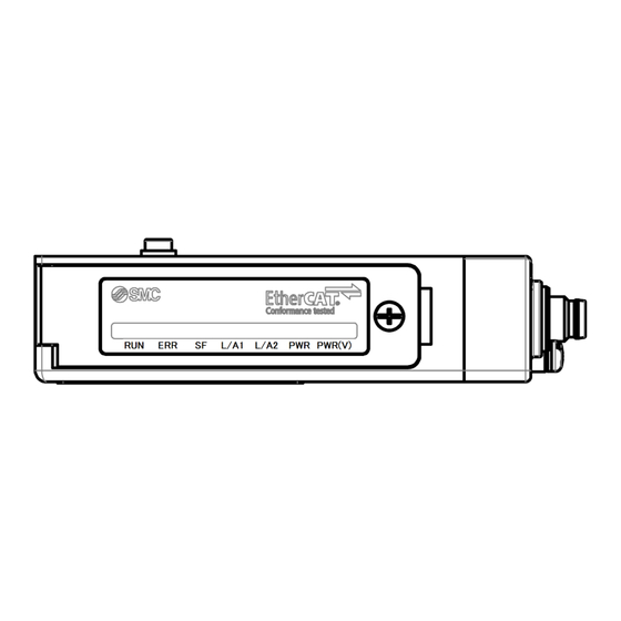
7. LED indication / Diagnosis history 7.1. LED indication L/A1 L/A2 PWR PWR(V) Colour Indication Description Init Blinking(2.5 Hz) Pre-Operational Green Single Flash Safe-Operational Flickering(10 Hz) Bootstrap Operational Double Flash Process Data Watchdog Timeout / EtherCAT Watchdog Timeout Single Flash Local Error Blinking(2.5 Hz) Invalid Configuration... -
Page 25: Diagnosis History
Blinking (2.5Hz) Single Flash 200ms 200ms 200ms Flickering (10Hz) Double Flash 50ms 200ms 50ms 200ms Flashing (0.5Hz) Fig 7-2. LED lighting patterns 7.2. Diagnosis history Table 7-1. Diagnosis history Message Type Description Valve short circuit on CH x Valve short circuit has occurred at CHx ejector. Pressure sensor short circuit Pressure sensor short circuit has occurred. -
Page 26: Specification
8. Specification 8.1. Specifications Table 8-1. Specifications Item Specification General IP67 (when connected with the vacuum manifold, it is IP65) Protection class CE/UKCA Marking Standards 25.5 x 98.7 x 76.5 Dimensions (W x L x H) Housing material Weight 150 g Maximum number of ejectors Maximum number of sensors Withstand voltage... -
Page 27: Dimensions
8.2. Dimensions Fig 8-1. Dimensions of the SI Unit -27- No.DOC1048575-1... -
Page 28: Block Diagram
8.3. Block diagram The following figure shows the block diagram for the SI Unit and the vacuum manifold. M8 4-pin socket, A-coded Ejector valve ① Communication max. 16 ② connector ③ (ECAT IN) ④ Pressure sensor max. 16 Logic circuit M8 4-pin socket, A-coded ①... -
Page 29: Accessories
9. Accessories (1) Seal cap Part number: EX9-AWES This cap is used to protect the M8 socket connector opening when the connector is not used. Proper use of the seal cap ensures the dustproof and waterproof performance (protection class) of the product. -
Page 30: Troubleshooting
10. Troubleshooting The state of the SI Unit is indicated by the LED indication. If a problem occurs on the SI Unit, you can use the following chart to troubleshoot. Also refer to the online diagnostics via the EtherCAT controller software to help identify the problem. ®... -
Page 31: Troubleshooting Tables
10.2. Troubleshooting tables Table 10-1. Troubleshooting "PWR LED is OFF or flashing" State Probable causes Checking methods and measures Check the power cable wiring. Incorrect wiring. Check the wiring and pin numbers, refer to Section 2.2. PWR LED is OFF. Power supply for logic/input ... - Page 32 Table 10-5. Troubleshooting "SF LED is red ON" State Probable causes Checking methods and measures Refer to Diagnosis history (Section 7.2) to identify which CH(s) have a short circuit. Valve has a short circuit. Refer to the manual for vacuum manifold to check the relevant ejector(s) connections and replace the ejector(s) if necessary.
- Page 33 Revision history 1: Correction of erroneous description 4-14-1, Sotokanda, Chiyoda-ku, Tokyo 101-0021 JAPAN Tel: + 81 3 5207 8249 Fax: +81 3 5298 5362 https://www.smcworld.com Note: Specifications are subject to change without prior notice and any obligation on the part of the manufacturer. ©...
Need help?
Do you have a question about the EtherCAT EX260-VEC1 and is the answer not in the manual?
Questions and answers