
Subscribe to Our Youtube Channel
Related Manuals for SMC Networks EX260-VEN1


Summary of Contents for SMC Networks EX260-VEN1
- Page 1 Doc. No.EX##-OMA1004 PRODUCT NAME SI Unit for vacuum manifold MODEL / Series / Product Number EX260-VEN1...
- Page 2 Contents 1. Product summary 2. Wiring 2.1. Communication connector 2.2. Power connector 2.3. FE terminal 3. Configuration 3.1. EDS file and Icon file 3.2. Switch setting 3.3 . Configuration with Studio 5000 Logix Designer 3.4 . EtherNet/IP function 4 . Process data 4.1.
- Page 3 Safety Instructions These safety instructions are intended to prevent hazardous situations and/or equipment damage. These instructions indicate the level of potential hazard with the labels of "Caution", "Warning" or "Danger". They are all important notes for safety and must be followed in addition to International Standards (ISO/IEC) , and other safety regulations.
- Page 4 Safety Instructions Caution 1.The product is provided for use in manufacturing industries. The product herein described is basically provided for peaceful use in manufacturing industries. If considering using the product in other industries, consult SMC beforehand and exchange specifications or a contract if necessary. If anything is unclear, contact your nearest sales branch.
- Page 5 Operator This operation manual is intended for those who have knowledge of machinery using pneumatic equipment, and have sufficient knowledge of assembly, operation and maintenance of such equipment. Only those persons are allowed to perform assembly, operation and maintenance. Read and understand this operation manual carefully before assembling, operating or providing maintenance to the product.
- Page 6 Caution ■When handling or assembling or replacing the unit, pay attention to the following: •Do not touch the sharp edges when overseeing the unit. •The unit joints are tightly bound with gaskets, so do not hit your hands when replacing the unit. •Do not put your fingers between them when joining the units.
- Page 7 •Product handling Installation •Do not drop, hit or apply excessive shock to the fieldbus system. Otherwise, damage to the product can result, causing malfunction. •Tighten to the specified tightening torque. If the tightening torque is exceeded the mounting screws may be broken. IP65 protection cannot be guaranteed if the screws are not tightened to the specified torque.
- Page 8 •Mount the product in a place that is not exposed to excessive vibration or impact. Otherwise, failure or malfunction can result. •Do not use the product in an environment that is exposed to temperature cycle. Heat cycles other than ordinary changes in temperature can adversely affect the inside of the product. •Do not expose the product to direct sunlight.
- Page 9 Fieldbus System/ Industrial IoT Cybersecurity In recent years, factories have introduced industrial IoT, building up complex networks of production machines. These systems maybe subject to a new threat, cyberattack. To protect the industrial IoT from cyberattacks, it is important to take multiple measures (multi-layer protection) for IoT devices, networks and clouds.
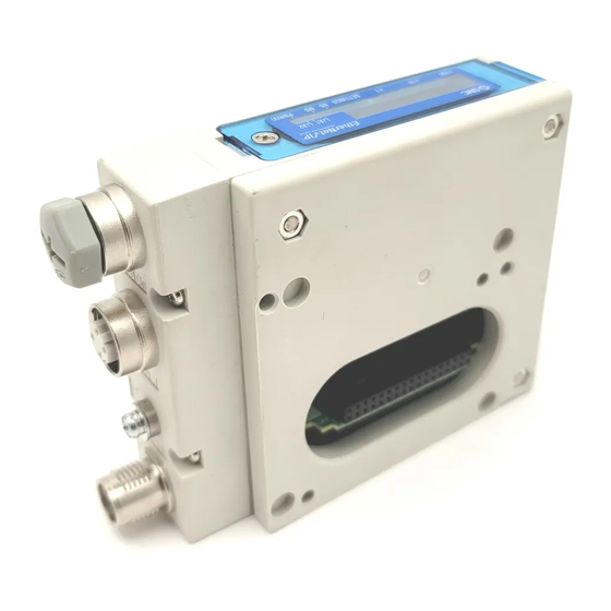
- Page 10 1. Product summary This document is an operation manual for a SI (Serial Interface) Unit which controls vacuum (ejector) manifold (ZKJ series). The SI Unit is compatible with EtherNet/IP . The SI Unit controls a vacuum manifold which has 16 supply valves max., 16 release valves max. and 16 pressure sensors max.. Item Description EtherNet/IP...
- Page 11 2. Wiring Select the appropriate cables to mate with the connectors mounted on the SI Unit, refer to Section 2.1. Communication connector BUS IN/Port 1 BUS OUT/Port2 Port type : MDI Port type : MDI-X Pin No. Designation Content Designation Content Transmit Data + Receive Data +...
- Page 12 The following Fig. 2-3 shows wiring examples of the use of two cable types. Patch cable Pin No. Pin No. MDI-X TD+ Transmit data+ RD+ Receive data+ RD+ Receive data+ TD+ Transmit data+ TD+ Transmit data- RD- Receive data- RD- Receive data- TD+ Transmit data- Crossover cable Pin No.
- Page 13 2.2. Power connector Pin No. Designation Content 24 V (PWR) 24 VDC for logic/input 24 V (PWR(V)) 24 VDC for output 0 V (PWR) 0 VDC for logic/input 0 V (PWR(V)) 0 VDC for output M12 4 pin socket A-coded connector (PWR) Fig 2.4 Pin allocation of power connector The power supply for logic/input (PWR) and the power supply for output (PWR(V)) are isolated.
- Page 14 3. Configuration 3.1. EDS file and Icon file The compatible EDS file is required to configure the SI Unit within an EtherNet/IP network. Download the latest EDS files from our website. URL : https://www.smcworld.com EDS files and icon files are as follows. EDS file : ex260_ven_v*.eds ...
- Page 15 *1 : Remote control (Set rotary switch for IP address X to 000) This mode is compatible with the IP address setting software EX9-ZSW-IPC1 and EX9-ZSW-IPC2. Using EX9-ZSW-IPC1, you can set up to 200 IP addresses while checking the MAC addresses of connected devices.
- Page 16 3.3. Configuration with Studio 5000 Logix Designer Shows how to connect an SI Unit to a Rockwell Automation EtherNet/IP module (PLC). Examples are given here using Studio 5000 Logix Designer. For detailed operating instructions, refer to the Studio 5000 Logix Designer operation manual. Note ...
- Page 17 - The Select Module Type screen is displayed. Select ETHERNET-MODULE Generic Ethernet Module and click the Create button. Fig 3.3 Configuration procedure without EDS file 2 -17- No.EX##-OMA1004...
- Page 18 - The New Module screen is displayed. Make various settings. (1) Name : Enter any unit name. (2) Comm : Select the data format for Connection Parameters. (3) IP Address : Enter the IP address set for the SI Unit. (4) Assembly Instance : Enter as shown below.
- Page 19 3.3.2. To set up with EDS file - Install the EDS file beforehand using the Rockwell Automation software Rockwell EDS Wizard Tool or similar. For installation instructions, refer to the manual of the Rockwell EDS Wizard Tool or other software. When the EDS file is installed, the SI Unit part number will be added to the Select Module screen.
- Page 20 - The New Module screen is displayed. Make various settings. (1) Name : Enter any unit name. (2) IP Address : Enter the IP address set for the SI Unit. Fig 3.6 Configuration procedure with EDS file 2 (3) If DIP switch No.2 is ON, click the Change button and set Input Size to 38 byte. Fig 3.7 Configuration procedure with EDS file 3 -20- No.EX##-OMA1004...
- Page 21 3.4. EtherNet/IP function 3.4.1. DLR(Device Level Ring) function The SI Unit can be used as an EtherNet/IP compliant Ring Node supporting the DLR function. To enable the DLR function, all Ring Nodes must support the DLR function. All settings for the DLR function are made by the Ring Supervisor, so there are no settings that need to be made on the SI Unit.
- Page 22 4. Process data 4.1. Input process data Table 4.1 Overview of input process data byte Content Description Vacuum status of CH0...7 Refer to Section 4.1.1. Vacuum status of CH8...15 Release status of CH0...7 Refer to Section 4.1.2. Release status of CH8...15 Unit status Refer to Sectioin...
- Page 23 4.1.2. Release status Table 4.3 Release status byte Content Description Release status of CH0 ejector Release status of CH1 ejector Release status of CH2 ejector Release status of CH3 ejector Release status of CH4 ejector Release status of CH5 ejector Release status of CH6 ejector Release status of CH7 ejector 0 : No vacuum release...
- Page 24 4.1.4. Pressure value and channel status Occupied when DIP switch No. 2 is ON (refer to Section 3.2). The input process data for pressure value and channel status occupy 2 byte per ejector CH. Of these, 12 bit is pressure value, and 4 bit is channel status (diagnostic data). Table 4.5 Pressure value and channel status byte n+1 (n = 6,8,...,36) byte n (n = 6,8,...,36)
- Page 25 4.2. Output process data Table 4.9 Overview of output process data byte Content Description Vacuum instruction of CH0 ejector Release instruction of CH0 ejector Vacuum instruction of CH1 ejector Release instruction of CH1 ejector Vacuum instruction of CH2 ejector Release instruction of CH2 ejector Vacuum instruction of CH3 ejector Release instruction of CH3 ejector Vacuum instruction of CH4 ejector...
- Page 26 5. Web server The SI Unit has a web server function. From a PC web browser, you can perform checking SI Unit's diagnostics, setting parameters and forcing output etc.. Connect the SI Unit and the PC to the same Ethernet network and launch the PC's web browser. Enter the IP address of the SI Unit in the address bar of the web browser to connect to the web server.
- Page 27 5.1. I/O Status tab ② ③ ① ⑥ ④ ⑤ ⑬ ⑫ ⑨ ⑪ ⑩ ⑦ ⑧ Fig 5.1 I/O Status tab 1 Table 5.2 I/O Status tab content 1 Item Description IP Address Displays the IP address of the SI Unit. Displays the status of Force Output mode.
- Page 28 ⑭ ⑮ ⑯ Fig 5.2 I/O Status tab 2 Table 5.3 I/O Status tab content 2 Item Description Displays the pressure value and the channel status of the input process data. Refer to Section 4.1.4. 14 INPUT DATA EXT. Also notes pressure values in kPa. Not displays when DIP switch No.
- Page 29 5.1.1. Change Password Change the password to be entered when Force Output or writing parameters etc.. Fig 5.3 Change password Enter the current password in the "Old password" field and the new password in the "New password" and "Confirm password" fields and click the OK button to complete the password change. Note ...
- Page 30 5.1.3. Zero Clear OFF Resets the zero clear correction value. Password transmission required. Fig 5.5 Zero clear OFF Note Zero clear and zero clear reset are conducted in batches for all CHs. Zero clearing should be conducted with the residual pressure is exhausted and the air is released in all CHs.
- Page 31 5.1.5. Force Output Shifts to Force Output mode. After the password is sent, the Force output field becomes Active. Fig 5.7 Force Output When shifts to Force Output mode, the OUTPUT DATA (output process data) can be edited. The edited OUTPUT DATA is displayed in characters.
- Page 32 5.2. Parameter Setting tab ③ ② ④ ① Fig 5.9 Parameter Setting tab Table 5.4 Parameter Setting tab content Item Description Edit various parameters for each ejector CH. Refer to various parameters from Section 5.2.1 onwards. Parameter The parameter being edited is displayed with red text and yellow background.
- Page 33 5.2.1. Vacuum Ejector Table 5.5 Vacuum Ejector Parameter Value Default Description Set the ejector used/unused. If set to Disable, the pressure value of the relevant CH is fixed to 0 and the diagnosis of Disable pressure sensor failure/disconnection is invalid. Vacuum Ejector Enable Enable...
- Page 34 5.2.5. Setpoint P2 Table 5.9 Setpoint P2 Parameter Value Default Description Set energy saving operation threshold (P2). 21...999 Setpoint P2 Set the negative pressure (vacuum pressure) by integer in (-2.1...-99.9kPa) (-75kPa) units of -0.1 kPa. 5.2.6. Hysteresis H2 Table 5.10 Hysteresis H2 Parameter Value Default...
- Page 35 5.2.11. Count X1 Table 5.15 Count X1 Parameter Value Default Description Set Enable/Disable valve protection function and its number of times. The valve protection functions are described below. During operation of energy saving function, if the switching of vacuum Count X1 0...100 generate/stop has reached set number of times, stop subsequent energy saving function and diagnostic information is issued.
- Page 36 5.3. Interface Status tab ① ⑥ ② ⑦ ③ ④ ⑤ ⑧ ⑨ ⑩ ⑪ ⑫ ⑬ Fig 5.11 Interface Status tab Table 5.16 Interface Status tab content Item Description IP Address Displays the current IP address. SubnetMask Displays the current subnet mask. DefaultGateway Displays the current default gateway address.
- Page 37 5.4. Statistics tab Displays error counter information for communication port 1 (BUS IN) and port 2 (BUS OUT). Fig 5.12 Statistics tab 5.5. Diagnostic tab Displays the communication status of the SI Unit and sets the QuickConnect function. Fig 5.13 Diagnostic tab -37- No.EX##-OMA1004...
- Page 38 5.6. Hold Clear tab ① ② ③ Fig 5.14 Hold Clear tab Table 5.19 Hold Clear tab content Item Description Displays/edits the energising action to the valve in the event of a communication error. C : Clear (yellow background) : Turns off the energisation instruction to the valve in HOLD/CLEAR the event of a communication error.
- Page 39 6. Example of energy saving operation of ejector Positive pressure Pressure of release status Atmospheric Time pressure Pressure of vacuum status Energy saving function Negative Vacuum instruction Open Supply valve Closed Release instruction Open Release Valve Closed Vacuum status Release status Fig 6.1 Sample of ejector operation ...
- Page 40 7. LED display L/A1 L/A2 PWR(V) Status Description Power supply for logic/input is not present or IP address not set. (Not powered, no IP address) Green ON EtherNet/IP connection established. (Connected) Green flashing(1 Hz) EtherNet/IP connection not established. (No connections) Red flashing(1 Hz) EtherNet/IP connection timeout.
- Page 41 8. Specification 8.1. Dimensions Fig 8.1 Dimensions of the SI Unit -41- No.EX##-OMA1004...
- Page 42 8.2. Specifications Table 8.1 Specifications Item Specification General Dimensions (W x L x H)mm 25.5 x 102.4 x 76.5 Weight 150 g Housing materials Maximum number of ejectors Maximum number of sensors Applicable standard CE/UKCA Marked、RoHS directive Withstand voltage 500 VAC、1 min (between FE and all accessible terminals) 10 Mohm or more (500 VDC between FE and all accessible Insulation resistance terminals)
- Page 43 9. Accessories 9.1. Accessories for communication connector 9.1.1. Cable with communication connector (SPEEDCON) Part number : PCA-1446566 Item Specification Pin No. Cable colour : Signal Connector M12 Straight (SPEEDCON) Yellow : TD+ Cable length 5000 mm White : RD+ Cable O.D. Φ...
- Page 44 9.1.3. Cable with communication connector (M12 - RJ45) Part number : EX9-AC 01 0EN-PSRJ Cable length (L) 1000 [mm] 2000 [mm] 3000 [mm] 5000 [mm] 10000 [mm] Item Specification M12 Straight RJ45 Connector Cable O.D. Φ 6.4 mm Electric wire cross section 0.14 mm /AWG26 Min.
- Page 45 9.1.4. Cable with communication connector (M12 - M12, Straight) Part number : EX9-AC 005 EN-PSPS Cable length (L) 500 [mm] 1000 [mm] 2000 [mm] 3000 [mm] 5000 [mm] 10000 [mm] Item Specification Pin No. Cable colour : Signal M12 Straight M12 Straight Connector Yellow : TD+ Cable O.D.
- Page 46 9.1.5. Cable with communication connector (M12 - M12, Angle) Part number : EX9-AC 005 EN-PAPA Cable length (L) 500 [mm] 1000 [mm] 2000 [mm] 3000 [mm] 5000 [mm] 10000 [mm] Item Specification Pin No. Cable colour : Signal M12 Angle M12 Angle Connector Yellow : TD+ Cable O.D.
- Page 47 9.2. Accessories for power connector 9.2.1. Cable with power supply connector Part number : EX500-AP0 1 0- S Connector specification Straight Angle Cable length (L) 1000 mm 5000 mm EX500-AP0x0-S EX500-AP0x0-A Item Specification Pin No. Cable colour : Signal Cable O.D. Φ...
- Page 48 9.2.2. Cable with power supply connector (SPEEDCON) Part number : PCA-140180 4 Cable length(L) 1500 mm 3000 mm 5000 mm Item Specification Pin No. Cable colour : Signal Brown : 24 VDC (For logic/input) M12 Straight Connector (SPEEDCON) White : 24 VDC (For output) Cable O.D.
- Page 49 10. Troubleshooting The state of the SI Unit is indicated by the LED indication. If a problem occurs on the SI Unit, you can use the following chart to troubleshoot. Also refer to the online diagnostics via the PLC software to help identify the problem. 10.1.
- Page 50 10.2. Troubleshooting tables Table 10.1 Troubleshooting "MS LED is OFF" State Probable causes Checking methods and measures Check the power cable wiring. Incorrect power wiring. Check the pin number and wiring of the power connector, Refer to Section.2.2. MS LED is OFF.
- Page 51 Table 10.5 Troubleshooting "MS LED is red flashing" State Probable causes Checking methods and measures Refer to the manual for the vacuum manifold to Pressure sensor has a short check all ejectors connections and replace the circuit. ejector(s) if necessary. ...
- Page 52 Table 10.9 Troubleshooting "NS LED is red flashing" State Probable causes Checking methods and measures Check the connection of the communication connector and the communication cable. NS LED is red EtherNet/IP connection If disconnected, replace the cable. flashing. timeout. ...
- Page 53 Revision history 4-14-1, Sotokanda, Chiyoda-ku, Tokyo 101-0021 JAPAN Tel: + 81 3 5207 8249 Fax: +81 3 5298 5362 https://www.smcworld.com Note: Specifications are subject to change without prior notice and any obligation on the part of the manufacturer. EtherNet/IP is a trademark of ODVA. QuickConnect is a trademark of ODVA.
Need help?
Do you have a question about the EX260-VEN1 and is the answer not in the manual?
Questions and answers