
Subscribe to Our Youtube Channel
Related Manuals for SMC Networks EX260-SEN1-X242


Summary of Contents for SMC Networks EX260-SEN1-X242
- Page 1 No.EX※※-OMA1009 PRODUCT NAME SI unit for Modbus/TCP MODEL / Series / Product Number EX260-SEN1-X242...
-
Page 2: Table Of Contents
Table of Contents Safety Instructions Model Indication and How to Order Summary of Product parts Definition and terminology Installation and Wiring Installation Wiring LED Indication and Settings Modbus/TCP Register Function Code Web server function Troubleshooting and Maintenance Specification Specifications Dimensions Accessories No.EX※※-OMA1009... -
Page 3: Safety Instructions
Safety Instructions These safety instructions are intended to prevent hazardous situations and/or equipment damage. These instructions indicate the level of potential hazard with the labels of "Caution", "Warning" or "Danger". They are all important notes for safety and must be followed in addition to International Standards (ISO/IEC) , and other safety regulations. - Page 4 Safety Instructions Caution 1.The product is provided for use in manufacturing industries. The product herein described is basically provided for peaceful use in manufacturing industries. If considering using the product in other industries, consult SMC beforehand and exchange specifications or a contract if necessary. If anything is unclear, contact your nearest sales branch.
- Page 5 Operator This operation manual is intended for those who have knowledge of machinery using pneumatic equipment, and have sufficient knowledge of assembly, operation and maintenance of such equipment. Only those persons are allowed to perform assembly, operation and maintenance. Read and understand this operation manual carefully before assembling, operating or providing maintenance to the product.
- Page 6 ■NOTE ○Follow the instructions given below when designing, selecting and handling the product. •The instructions on design and selection (installation, wiring, environment, adjustment, operation, described below must also be followed. maintenance, etc.) Product specifications •When conformity to UL is required, the SI unit should be used with a UL1310 Class 2 power supply. •The SI unit is a "UL"...
- Page 7 •Product handling Installation •Do not drop, hit or apply excessive shock to the fieldbus system. Otherwise damage to the product can result, causing malfunction. •Tighten to the specified tightening torque. If the tightening torque is exceeded the mounting screws may be broken. IP67 protection cannot be guaranteed if the screws are not tightened to the specified torque.
- Page 8 •Mount the product in a place that is not exposed to vibration or impact. Otherwise failure or malfunction can result. •Do not use the product in an environment that is exposed to temperature cycle. Heat cycles other than ordinary changes in temperature can adversely affect the inside of the product. •Do not expose the product to direct sunlight.
-
Page 9: Model Indication And How To Order
Model Indication and How to Order EX260-SEN1-X242 Protocol Modbus/TCP Polarity of output PNP (negative common)/source No.EX※※-OMA1009... -
Page 10: Summary Of Product Parts
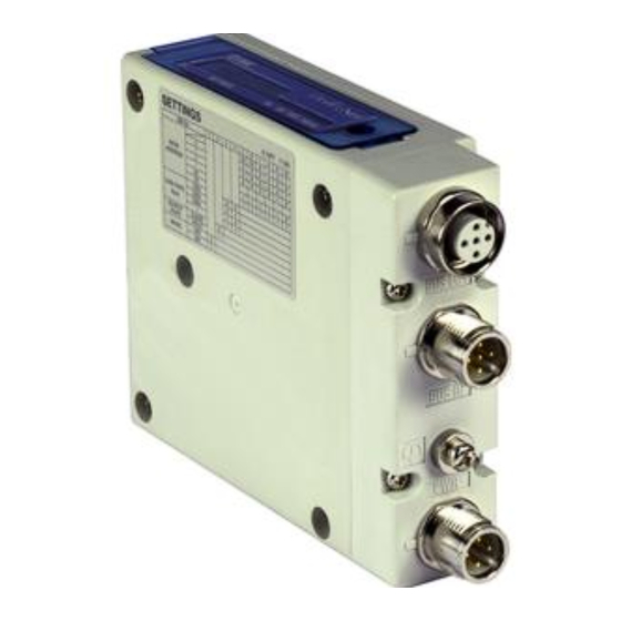
Summary of Product parts Element Description 1 Fieldbus interface connector Modbus/TCP connection PORT 2. (BUS OUT) (M12 4-pin socket, D-coded) 1 Fieldbus interface connector Modbus/TCP connection PORT 1. (BUS IN) (M12 4-pin socket, D-coded) 1 Power supply with load voltage for valves and operating voltage for SI unit. Power supply connector (M12 4-pin plug, A-coded) FE terminal... -
Page 11: Definition And Terminology
■Definition and terminology Terms Meaning 100BASE-TX Standard of LAN transmission line with communication speed of 100 Mbps. The signal from the analogue input device is converted to digital, and displayed in AD value decimal and hexadecimal. These hexadecimal and decimal values are also outputted to the analogue output device. -
Page 12: Installation And Wiring
Installation and Wiring ■Installation Connect valve manifold to the SI unit. •Dimensions for installation n: number of valve stations 120.7 136.7 152.7 168.7 184.7 200.7 216.7 232.7 248.7 264.7 280.7 296.7 312.7 328.7 344.7 (mm) The above table shows dimensions as an example for the SY5000 series valve manifold. Refer to the valve manifold section in the valve catalogue for valve manifold dimensions. -
Page 13: Wiring
■Wiring Select the appropriate cables to mate with the connectors mounted on the SI unit. ○Fieldbus interface connector layout BUS IN and BUS OUT: M12 4-pin socket, D-coded Designation Description Transmit Data + Receive Data + Transmit Data - Receive Data - Connect the "BUS IN"... - Page 14 ○Power supply connector layout PWR: M12 4-pin plug, A-coded Designation Description SI24 V +24 V for SI unit operation SV24 V +24 V for solenoid valve SI0 V 0 V for SI unit operation SV0 V 0 V for solenoid valve Power-supply line for solenoid valve and power-supply line for SI unit operation are isolated.
- Page 15 ○FE terminal The SI Unit must be connected to FE (Functional Earth) to divert electromagnetic interference. For maximum protection, the FE cable should be as thick and short as reasonably possible. The FE terminal and the metal parts of the fieldbus interface/power supply connector are internally connected.
-
Page 16: Led Indication And Settings
LED Indication and Settings ○LED indication LED Status Description The SI unit operating voltage is not supplied or No Link. Green ON Modbus/TCP communications established. Green flashing Modbus/TCP communications not established. Red flashing Query data time out. The SI unit operating voltage is not supplied. Green ON Operating normally. - Page 17 ○Switch setting The switches should only be set with the power supply turned off. Open the cover and set the rotary switches and DIP switch with a small flat blade screwdriver. Default settings are "Web setting" and all off. Default IP address of "Web setting" is 192.168.1.20. -16- No.EX※※-OMA1009...
- Page 18 ○Output number assignment Output data : The output numbering refers to the solenoid position on the manifold and starts at zero. : Standard wiring of the manifold is for double-solenoid valves and the output number starts at the A side and then B side in that order as shown in the figure a.
-
Page 19: Modbus/Tcp Register
Modbus/TCP Register The Modbus/TCP server occupies 4 types of registers, "Holding Registers", "Input Registers", "Coils" and "Discrete Inputs". The Client performs "Read" and "Write" commands to the Server registers by using Function Command for data communication. The content of the registers assigned to EX260 is shown below. 1) Holding Registers (performs Read/Write using 16 bits (word)) Range Process data... -
Page 20: Function Code
Function Code EX260 supports the function codes below. Function code name Function code Read Coils Read Discrete Inputs Read Holding Registers Read Input Registers Write Single Coil Write Single Register Write Multiple Coils Write Multiple Registers Read/Write Multiple Registers 1) Read Coils (01h) Register type: Coils This function code is used to read from 1 to 2000 contiguous status of coils. - Page 21 2) Read Discrete Inputs (02h) Register type: Discreate Inputs This function code is used to read from 1 to 2000 contiguous status of discrete inputs. •Request Size Contents Function code 1 byte Starting address 2 bytes 0000h to 000Fh Quantity of coils 2 bytes 0001h to 07D0h (2000) •Response...
- Page 22 3) Read Holding Registers (03h) Register type: Holding Registers This function code is used to read from 1 to 125 contiguous holding registers. •Request Size Contents Function code 1 byte Starting address 2 bytes 0000h to 0001h Quantity of registers 2 bytes 0001h to 007Dh (125) •Response...
- Page 23 5) Write Single Coil (05h) Register type: Coils This function code is used to write a single output to either ON or OFF. •Request Size Contents Function code 1 byte Output address 2 bytes 0000h to 001Fh Output value 2 bytes 0000h or FF00h •Response Size...
- Page 24 6) Write Single Register (06h) Register type: Holding Registers This function code is used to write a single holding register. •Request Size Contents Function code 1 byte Register address 2 bytes 0000h to 0001h Register value 2 bytes Write value •Response Size Contents...
- Page 25 8) Write Multiple Registers (10h) Register type: Holding Registers This function code is used to write a block of contiguous registers (1 to 123 registers). •Request Size Contents Function code 1 byte Starting address 2 bytes 0000h to 0001h Quantity of registers 2 bytes 0001h to 007Bh (123) ...
-
Page 26: Web Server Function
■Web server function The SI unit has a Web server function which allows checking the information from a PC Web browser during maintenance, or checking of I/O monitor or forced output of ON/OFF of the valve. •Connection of SI unit and PC Connect SI unit and PC to the same Ethernet network, then start the Web browser on the PC. - Page 27 Active: Force output mode enabled Inactive: Force output mode disabled SI unit I/O size settings. I/O Size 16 IN/32 OUT: EX260-SEN1-X242 settings Displays the communication status of the SI unit Modbus/TCP. Connection Establish: Modbus/TCP communication is established Network IP Address Configured: Modbus/TCP communication is not established Connection Timeout: Query data time out SI unit operating condition.
- Page 28 < Registers tab > Current SI unit Holding registers map and Input registers map are displayed. ② ① Item Meaning Force output Select for force output mode. Change password Select for changing the password to enable changing to force output mode. •Forced output mode Procedure to change to forced output more and the method of forced output.
- Page 29 Holding Registers becomes editable in forced output mode. Edited Holding Registers is displayed in red. After Holding Registers is edited, the Holding Registers will be reflected by selecting "Execute". Reflected Holding Registers is displayed in yellow. All Holding Registers can be cleared by selecting “Reset”. Forced output mode is released by selecting “Force output exit“.
- Page 30 •Password change Password can be changed by selecting the Change password button. Type the password before change in the "Old password" space, and the new password in the "New password" and "Confirm password" spaces. Password change is completed by selecting OK. <...
- Page 31 < Coils monitor tab > Current SI unit Coils map and Discrete Input map are displayed. < Hold/Clear tab > Hold/Clear settings of SI unit is displayed. •Hold/Clear settings Sets the output status when query data timeout is occurred. Clear: Output is OFF (default setting) Hold: Holds the output.
- Page 32 Edited Hold/Clear is displayed in red. After Hold/Clear is edited, the Hold/Clear will be reflected by selecting "Submit". -31- No.EX※※-OMA1009...
- Page 33 < Interface Status tab > Interface information including the SI unit MAC address and communication speed are displayed. X.XX •Network Config change In "Network Config" field, be able to change the IP Address, Subnet Mask, and Default Gateway of SI unit. These changed values will be reflected after the SI unit power restart.
- Page 34 < Statistics tab > Ethernet performance of SI unit is displayed. Interface Counter contains counters relevant to the receipt of packets on the interface. Media Counter contains counters specific to Ethernet media. -33- No.EX※※-OMA1009...
-
Page 35: Troubleshooting And Maintenance
Troubleshooting and Maintenance ○Troubleshooting chart When any malfunction is observed, it is recommended to perform the following troubleshooting. Refer to fault SI unit SI unit MS LED is No.1 malfunction Refer to fault SI unit PWR(V) LED No.2 is OFF Refer to fault SI unit L/A LED is No.3... - Page 36 Troubleshooting table Fault No.1 Fault Probable cause Recommended error handling Recommended action Re-tighten the power cable. (Replace the cable if it is Defective power Check the condition of the power cable SI unit broken) cable wiring for SI wiring to the SI unit. MS LED is unit operation Correct the power cable wiring...
- Page 37 Fault No.6 Fault Probable cause Recommended error handling Recommended action Tighten the communication Check the communication cable cable connection. connections and check for broken wires. (Replace the cable if it is SI unit broken) NS LED is red Query data time-out flashing Check that there are no high voltage cables Take measures to keep the...
- Page 38 ○Maintenance Replacement of the SI unit •Remove the M3 hexagon screws from the SI unit and release the SI unit from the valve manifold. •Replace the SI unit. •Tighten the screws with the specified tightening torque. (0.6 N•m) Precautions for maintenance (1) Be sure to switch off the power.
-
Page 39: Specification
Specification ■Specifications •General specifications Item Specifications Ambient temperature -10 to +50 Ambient storage 35 to 85%RH (No condensate) Ambient storage temperature -20 to +60 Withstand voltage 500 VAC applied for 1 minute 500 VDC, 10 MΩ or more Insulation resistance Operating atmosphere No corrosive gas IP67 rating to IEC 60529 (When fully installed or fitted with protective cover) - Page 40 •Modbus/TCP communication specifications Item Specifications Protocol Modbus/TCP Transmission medium Standard Ethernet cable (CAT5 or more) (100BASE-TX) Transmission speed 100 Mbps (Auto negotiation) Web setting (default: 192.168.1.20) IP address setting method DIP SW setting: 192.168.1.1 to 254 192.168.0.1 to 254 Read Coils (0x01) Read Discrete Inputs (0x02) Read Holding Resisters (0x03) Read Input Registers (0x04)
- Page 41 ○I/O Mapping Input area mapping Input data Offset (Word) SOLV L: Low fixed (0) Input status area Input status area specifications Item Status State Normal SOLV State of power supply for solenoid valve Abnormal (19 V or less) Output area mapping Output data Offset (Word)
-
Page 42: Dimensions
■Dimensions •If a fieldwireable connector is used for the power supply connection, and the SI unit is installed directly to a valve manifold, the connector should be 16 mm or less. If the connector is a larger diameter it will interfere with the clamping face. Recommended cables are specified in the accessories section, on page 42. -
Page 43: Accessories
Accessories ○Connector cable Suitable connector SI unit connector Description Part number Specifications Manufacturer EX9-AC010EN-PSRJ: 1 m EX9-AC020EN-PSRJ: 2 m Connector: M12 straight at EX9-AC030EN-PSRJ: 3 m one end and RJ45 Cable with EX9-AC050EN-PSRJ: 5 m at the other end communication Fieldbus EX9-AC100EN-PSRJ: 10 m connector... - Page 44 Revision history 4-14-1, Sotokanda, Chiyoda-ku, Tokyo 101-0021 JAPAN Tel: + 81 3 5207 8249 Fax: +81 3 5298 5362 https://www.smcworld.com Note: Specifications are subject to change without prior notice and any obligation on the part of the manufacturer. ® Modbus is a registered trademark of Schneider Electric, licensed to the Modbus Organization, Inc.
Need help?
Do you have a question about the EX260-SEN1-X242 and is the answer not in the manual?
Questions and answers