
Related Manuals for SMC Networks EX260-MEC1


Summary of Contents for SMC Networks EX260-MEC1
- Page 1 Doc. No. DOC1041432 PRODUCT NAME Fieldbus system EtherCAT compatible SI Unit ® MODEL / Series / Product Number EX260-MEC1...
-
Page 2: Table Of Contents
Contents 1. Product summary 1.1. Features 1.2. Parts and description 2. Installation 2.1. Mounting 2.2. Wiring 3. Configuration 3.1. ESI file 3.2. Slot setting 4. Process data 4.1. Input process data 4.2. Output process data 5. CoE 5.1. Output operation at network fault (Index 0x80x0) 5.2. - Page 3 Safety Instructions These safety instructions are intended to prevent hazardous situations and/or equipment damage. These instructions indicate the level of potential hazard with the labels of “Caution,” “Warning” or “Danger.” They are all important notes for safety and must be followed in addition to International Standards (ISO/IEC) , and other safety regulations.
- Page 4 Safety Instructions Caution The product is provided for use in manufacturing industries. The product herein described is basically provided for peaceful use in manufacturing industries. If considering using the product in other industries, consult SMC beforehand and exchange specifications or a contract if necessary. If anything is unclear, contact your nearest sales branch.
- Page 5 Operator This operation manual is intended for those who have knowledge of machinery using pneumatic equipment, and have sufficient knowledge of assembly, operation and maintenance of such equipment. Only those persons are allowed to perform assembly, operation and maintenance. Read and understand this operation manual carefully before assembling, operating or providing maintenance to the product.
- Page 6 Caution ■When handling or assembling or replacing the unit, pay attention to the following: •Do not touch the sharp edges when overseeing the unit. •The unit joints are tightly bound with gaskets, so do not hit your hands when replacing the unit. •Do not put your fingers between them when joining the units.
- Page 7 •Product handling Installation •Do not drop, hit or apply excessive shock to the fieldbus system. Otherwise, damage to the product can result, causing malfunction. •Tighten to the specified tightening torque. If the tightening torque is exceeded the mounting screws may be broken. IP67 protection cannot be guaranteed if the screws are not tightened to the specified torque.
- Page 8 •Mount the product in a place that is not exposed to excessive vibration or impact. Otherwise, failure or malfunction can result. •Do not use the product in an environment that is exposed to temperature cycle. Heat cycles other than ordinary changes in temperature can adversely affect the inside of the product. •Do not expose the product to direct sunlight.
- Page 9 Fieldbus System/ Industrial IoT Cybersecurity In recent years, factories have introduced industrial IoT, building up complex networks of production machines. These systems maybe subject to a new threat, cyberattack. To protect the industrial IoT from cyberattacks, it is important to take multiple measures (multi-layer protection) for IoT devices, networks and clouds. For this purpose, SMC recommends that the following measures are always taken into consideration.
-
Page 10: Product Summary
1. Product summary 1.1. Features The SI (Serial Interface) Unit is an EtherCAT compatible device for control of SMC pneumatic valve ® manifolds. EtherCAT is registered trademark and patented technology, licensed by Beckhoff Automation GmbH, ® Germany. The SI Unit controls a 64 station compatible manifold and has the following properties: ... -
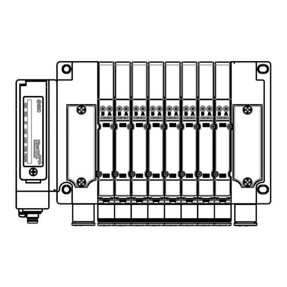
Page 11: Parts And Description
1.2. Parts and description Item Description Communication connector EtherCAT connection. (M8 4-pin socket, A-coded) ® (ECAT IN) Refer to Section 2.2.1. Communication connector EtherCAT connection. (M8 4-pin socket, A-coded) ® (ECAT OUT) Refer to Section 2.2.1. Power connector Power supply for control and valves. (M8 4-pin plug, A-coded) (PWR IN) Refer to Section... -
Page 12: Installation
2. Installation 2.1. Mounting 2.1.1. Valve manifold connection Connect the valve manifold with the 2 screws on the SI Unit. (Hexagonal socket wrench size 2.5 mm) Note Tighten the screws while holding the SI Unit and the valve manifold so that there is no gap between them. -
Page 13: Wiring
2.2. Wiring Connect the EtherCAT communication cables, the power cables and the FE cable. Select the appropriate cables to mate with the connectors and terminal mounted on the SI Unit. 1. M8 4-pin socket, A-coded, EtherCAT communication connector ECAT IN 2. - Page 14 2.2.2. Power connector PWR IN: M8 4-pin plug, A-coded Pin No. Designation Content 24 V (PWR) +24 V for control 24 V (PWR(V)) +24 V for valves 0 V (PWR) 0 V for control 0 V (PWR(V)) 0 V for valves PWR OUT: M8 4-pin socket, A-coded Pin No.
-
Page 15: Configuration
3. Configuration 3.1. ESI file To configure the SI Unit with your EtherCAT master's software, the dedicated ESI (EtherCAT Slave ® Information) file is required. The ESI file contains all necessary information to configure the SI Unit on your master's software. The ESI file name is as follows. -
Page 16: Process Data
4. Process data Table 4-1. Overview of process data Input/Output Index Name Size Description 0x1A00 Valve-coil(s) short circuit diagnosis List OUT0_7 0x1A01 Valve-coil(s) short circuit diagnosis List OUT8_15 0x1A02 Valve-coil(s) short circuit diagnosis List OUT16_23 0x1A03 Valve-coil(s) short circuit diagnosis List OUT24_31 0x1A04 Valve-coil(s) short circuit diagnosis List OUT32_39 0x1A05 Valve-coil(s) short circuit diagnosis List OUT40_47 0x1A06 Valve-coil(s) short circuit diagnosis List OUT48_55... -
Page 17: Input Process Data
4.1. Input process data (16 module sets) Valve-coil(s) short circuit diagnosis List 4.1.1. Table 4-2. V (16 module sets) alve-coil(s) short circuit diagnosis List Type Size Offset Name Description Indicate the short circuit diagnosis for one "8 valves" module together in one batch. USINT Output short circuit diagnosis OUTa_b 0[bin]: No short circuit... - Page 18 D side 1 station / 2 points a-side and b-side The slot settings are assigned process data for every 4 stations / 8 points. Index 0x160n Index 0x1A0n Output process data Input process data (Valve output) (Output short circuit diagnosis ) Slot Index Station...
-
Page 19: Coe
5. CoE This section describes the Index related to product specifications. Table 5-1. Overview of CoE Index *1 Subindex Name Flags *2 Description 0x70x0 Valve Output OUTa_b RO P Refer to Section 4.2.1. 0x80x0 Output operation at network fault OUTa_b Refer to Section 5.1. -
Page 20: Output Counter Limit Value (Index 0X80X1)
5.2. Output counter limit value (Index 0x80x1) Table 5-4. Output counter limit value Subindex Output Set value Default Description [hex] [Dec] 0x01 Set valve output counter limit value. 0x02 One Index contains 8 Subindex and can be set for each output. -
Page 21: Configured/Detected Modular Ident List (Index 0X90X0)
5.5. Configured/Detected Module Ident List (Index 0xF030/0xF050) Table 5-8. Configured/Detected Module Ident List Subindex Set/Read value Name (Slot) Description [hex] [hex] 0x01 OUT0_7 0x00000000(---) or 0x00020001 0x02 OUT8_15 0x00000000(---) or 0x00020002 0x03 OUT16_23 0x00000000(---) or 0x00020003 0x04 OUT24_31 0x00000000(---) or 0x00020004 Indicates whether "8 valves"... -
Page 22: Led Indication/Diagnosis History
6. LED Indication/Diagnosis history 6.1. LED Indication Colour Indication Description Init Blinking (2.5 Hz) Pre-Operational Green Single Flash Safe-Operational Flickering (10 Hz) Bootstrap Operational Double Flash EtherCAT Watchdog Timeout Blinking (2.5 Hz) Invalid Configuration No Error One of the following may have occurred. ... -
Page 23: Diagnosis History
Fig 6-2. LED lighting patterns 6.2. Diagnosis history Table 6-1. Diagnosis history Message Type Description Short circuit on OUTx A short circuit has occurred at OUTx. The valve manifold is not connected correctly. Valve circuit error (The SI Unit detected the number of valve stations to be 0 or more than 64.) Error Configuration error in... -
Page 24: Specification
7. Specification 7.1. Specifications Table 7-1. Specifications Item Specification General IP67 (when fully installed or fitted with protective cover) Protection class (complies with IEC 60529) CE/UKCA Marking, UL(CSA) Standards Dimensions (W x L x H) 34.2 x 98.7 x 76.5 Housing material Weight 200 g... -
Page 25: Dimensions
7.2. Dimensions Fig 7-1. Dimensions of the SI Unit -25- No.DOC1041432... -
Page 26: Block Diagram
0 V (PWR) 0 V (PWR(V)) (PWR OUT) 0 V (PWR(V)) ④ 0 V (PWR(V)) SI Unit 64 station compatible 64 station compatible (EX260-MEC1) manifold manifold (4 station manifold block) (4 station manifold block) Fig 7-2. Block diagram -26- No.DOC1041432... -
Page 27: Accessories
8. Accessories (1) Seal cap Part number: EX9-AWES This cap is used to protect the M8 socket connector opening when the connector is unused. When a connector is unused, the seal cap can keep the SI Unit under IP67 rated protection. (2 pcs. -
Page 28: Troubleshooting
9. Troubleshooting The state of the SI Unit is indicated by the LED indication. If a problem occurs on the SI Unit, you can use the following chart to troubleshoot. Also refer to the online diagnostics via the EtherCAT master software to help identify the problem. ®... -
Page 29: Troubleshooting Tables
9.2. Troubleshooting tables Table 9-1. Troubleshooting "PWR LED is OFF or flashing" State Probable causes Checking methods and measures Check the power cable wiring. Incorrect wiring. Check the wiring and pin numbers, refer to Section 2.2.2. PWR LED is OFF. Power supply for control (PWR) is ... - Page 30 Table 9-5. Troubleshooting "SF LED is red ON" State Probable causes Checking methods and measures Refer to operation manual of valve and Valve coil has a short circuit. check/replace the valve. Check the number of the valve stations The valve manifold is not connected connected to the SI Unit.
- Page 31 Revision history 4-14-1, Sotokanda, Chiyoda-ku, Tokyo 101-0021 JAPAN Tel: + 81 3 5207 8249 Fax: +81 3 5298 5362 https://www.smcworld.com Note: Specifications are subject to change without prior notice and any obligation on the part of the manufacturer. © 2023 SMC Corporation All Rights Reserved. No.DOC1041432...
Need help?
Do you have a question about the EX260-MEC1 and is the answer not in the manual?
Questions and answers