Advertisement
Quick Links
EX260-TF2Z167EN
ORIGINAL INSTRUCTIONS
Instruction Manual
Fieldbus device - SI unit for PROFINET
EX260-SPN1 / SPN2 / SPN3 / SPN4
The intended use of this SI unit is for the control of pneumatic valves
and I/O while connected to the PROFINET network.
1 Safety Instructions
These safety instructions are intended to prevent hazardous situations
and/or equipment damage. These instructions indicate the level of
potential hazard with the labels of "Caution," "Warning" or "Danger."
They are all important notes for safety and must be followed in addition
*1)
to International Standards (ISO/IEC)
, and other safety regulations.
*1)
ISO 4414: Pneumatic fluid power - General rules relating to systems.
ISO 4413: Hydraulic fluid power - General rules relating to systems.
IEC 60204-1: Safety of machinery - Electrical equipment of machines.
(Part 1: General requirements)
ISO 10218-1: Manipulating industrial robots -Safety. etc.
• Refer to product catalogue, Operation Manual and Handling
Precautions for SMC Products for additional information.
• Keep this manual in a safe place for future reference.
Caution indicates a hazard with a low level of risk which, if
Caution
not avoided, could result in minor or moderate injury.
Warning indicates a hazard with a medium level of risk
Warning
which, if not avoided, could result in death or serious injury.
Danger indicates a hazard with a high level of risk which, if
Danger
not avoided, will result in death or serious injury.
Warning
• Always ensure compliance with relevant safety laws and
standards.
• All work must be carried out in a safe manner by a qualified person in
compliance with applicable national regulations.
Caution
• Provide grounding to assure the safety and noise resistance of
the Fieldbus system.
Individual grounding should be provided close to the product using a
short cable.
• When conformity to UL is required the SI unit must be used with
a UL1310 Class 2 power supply.
2 Specifications
2.1 General specifications
Item
Specifications
o
Ambient temperature
-10 to +50
C
Ambient humidity
35 to 85%RH (No condensate)
o
Ambient storage temperature
-20 to +60
C
Withstand voltage
500 VAC applied for 1 minute
Insulation resistance
500 VDC, 10 MΩ or more
Operating atmosphere
No corrosive gas
Enclosure
IP67
Weight
200 g or less
2.2 Electrical specifications
Item
Specifications
21.6 to 26.4 VDC
Controller power supply
0.1 A max.
Power supply
voltage range
22.8 to 26.4 VDC
/ current
Solenoid valve power
2.0 A or less, according
consumption
supply
to the solenoid valve
station specification
EX260-SPN1
PNP (negative common)
EX260-SPN3
/ source
Output
type
EX260-SPN2
NPN (positive common) /
EX260-SPN4
sink
Output condition at the time
HOLD / CLEAR /
of communication error
Force ON
Solenoid
valve
Solenoid valve with
specification
surge voltage
Connected load
suppressor of 24 VDC
and 1.0 W or less
(manufactured by SMC)
Insulation type
Photo coupler
Residual voltage
0.4 VDC or less
2.3 Communication specifications
Item
Specifications
PROFINET IO (PROFINET RT)
Protocol
(specification version 2.3)
Standard Ethernet cable (CAT5)
Transmission medium
(100BASE-TX)
Transmission speed
100 Mbps
EX260-SPN1
32 outputs
EX260-SPN2
Number of
outputs
EX260-SPN3
16 outputs
EX260-SPN4
Vendor ID
0083 hex
Device ID
0001 hex
Conformance class
Class C (only for IRT switch function)
FSU (Fast Start Up)
Applicable function
MRP (Media Redundancy Protocol)
GSD file (download from the SMC
Configuration file
website)
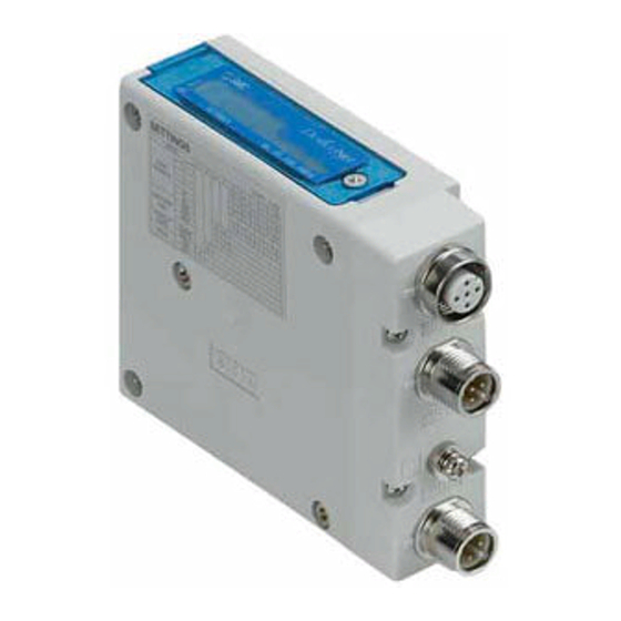
3 Name and function of parts
No
Part
Description
Fieldbus connector
PROFINET connection PORT2
1
(BUS OUT)
(M12 4-pin socket, D-coded)
Fieldbus connector
PROFINET connection PORT 1
2
(BUS IN)
(M12 4-pin socket, D-coded)
Power supply
Power supply for valves and operation of SI
3
connector
unit (M12 5-pin plug, A-coded)
4
Ground terminal
Functional Earth (M3)
5
Output connector
Output signal interface for valve manifold
6
LED display
Bus status specific and SI unit status LED's
Mounting hole for connection to the valve
7
Mounting hole
manifold
4 Installation
4.1 Installation
Warning
• Do not install the product unless the safety instructions have been
read and understood.
• General instructions on installation and maintenance
Connect the valve manifold to the SI unit.
• Assembly and disassembly of the SI unit
4.2 Replacement of the SI unit
• Remove the M3 hexagon screws from the SI unit and release the SI
unit from the valve manifold.
• Replace the SI unit.
• Tighten the screws with the specified tightening torque. (0.6 N•m)
4 Installation (continued)
4.3 Assembly Precautions
• Be sure to switch off the power.
• Check there is no foreign matter inside the SI unit.
• Check there is no damage and no foreign matter stuck to the gasket.
• Be sure to tighten the screws with the specified torque.
• If the SI unit is not assembled properly, the internal PCBs may be
damaged or liquid and/or dust may enter into the unit.
4.4 Connecting Cables
Select the appropriate cables to mate with the connectors mounted on
the SI unit.
• Fieldbus interface connector layout
BUS OUT: M12 4-pin socket, D-coded (SPEEDCON)
No.
Designation
Description
1
TD+
Transmit Data +
2
RD+
Receive Data +
3
TD-
Transmit Data -
4
RD-
Receive Data -
BUS IN: M12 4-pin socket, D-coded (SPEEDCON)
No.
Designation
Description
1
TD+
Transmit Data +
2
RD+
Receive Data +
3
TD-
Transmit Data -
4
RD-
Receive Data -
• Power supply connector layout
PWR: M12 4-pin plug, A-coded (SPEEDCON)
No.
Designation
Description
1
SV24V
+24 V for solenoid valve
2
SV0V
0 V for solenoid valve
3
SI24V
+24 V for SI unit operation
4
SI0V
0 V for SI unit operation
5
-
Not used
• The power supply for the solenoid valve and SI unit operation are
isolated. Be sure to supply power respectively.
Either single source power or two different power supplies can be
used.
NOTE
When conformity to UL is required the SI unit must be used with a
UL1310 Class 2 power supply.
The M12 connector cable for fieldbus and power supply connections
has two types, Standard M12 and SPEEDCON compatible. If both
plug and socket have SPEEDCON connectors, the cable can be
inserted and connected by turning it a 1/2 of a rotation, leading to a
reduction in man hours.
A standard connector can be connected to a SPEEDCON connector.
Warning
• Be sure to fit a seal cap (EX9-AWTS) on any unused connectors.
Proper use of the seal cap enables the enclosure to maintain IP67
specification.
4.5 Ground Terminal
• Connect the ground terminal to ground.
• Individual grounding should be provided close to the product with a
short cable to assure the safety and noise resistance of the Fieldbus
system.
• Resistance to ground should be 100 ohms or less.
4.6 Environment
Warning
• Do not use in an environment where corrosive gases, chemicals, salt
water or steam are present.
• Do not install in a location subject to vibration or impact in excess of
the product's specifications.
Page 1 of 2
Advertisement

Related Manuals for SMC Networks EX260-SPN1


Summary of Contents for SMC Networks EX260-SPN1
- Page 1 • If the SI unit is not assembled properly, the internal PCBs may be Ambient storage temperature -20 to +60 EX260-SPN1 / SPN2 / SPN3 / SPN4 damaged or liquid and/or dust may enter into the unit. Withstand voltage 500 VAC applied for 1 minute Insulation resistance 500 VDC, 10 MΩ...
- Page 2 Description Product number GSD file This product shall not be disposed of as municipal waste. Check your EX260-SPN1 / -SPN2 Operating normally local regulations and guidelines to dispose of this product correctly, in GSDML-V2.3-SMC-EX260-∗∗∗∗∗∗∗∗.xml order to reduce the impact on human health and the environment.
Need help?
Do you have a question about the EX260-SPN1 and is the answer not in the manual?
Questions and answers