Table of Contents
Advertisement
Quick Links
Advertisement
Table of Contents

Summary of Contents for Leuze electronic DCR 40
- Page 1 DCR 40 Scan Engine O r i g i n a l o p e r a t i n g i n s t r u c t i o n s...
-
Page 2: Table Of Contents
Installing the communication DTM and the device DTM ........... 17 6.2.4 Connecting device to PC .................... 17 Starting the Sensor Studio configuration software.............. 18 Exiting Sensor Studio ...................... 19 Configuration parameters ..................... 19 6.5.1 Control tab ......................... 20 6.5.2 Decode tab ........................ 21 6.5.3 Communications tab...................... 22 6.5.4 Diagnosis / Terminal...................... 23 Leuze electronic DCR 40... - Page 3 11.1 What to do should servicing be required? ................ 72 Technical data ..................... 73 12.1 General specifications ...................... 73 12.2 Reading fields ........................ 74 12.3 Dimensioned drawings ...................... 76 Order guide and accessories................ 77 13.1 Type overview........................ 77 13.2 Accessories........................... 77 Leuze electronic DCR 40...
- Page 4 Table of contents EC Declaration of Conformity................ 78 Appendix...................... 79 15.1 Bar code samples ......................... 79 15.2 Configuration via configuration codes................... 80 Leuze electronic DCR 40...
-
Page 5: About This Document
(Field Device Tool) Functional earth Graphical user interface Device class for input devices with which users directly interact (Human Interface Device) IO or I/O Input/Output (Light Emitting Diode) Programmable Logic Control (corresponds to Programmable Logic Controller (PLC)) Leuze electronic DCR 40... -
Page 6: Safety
Ä The device must not be opened. There are no user-serviceable parts inside. Ä Repairs must only be performed by Leuze electronic GmbH + Co. KG. Leuze electronic DCR 40... -
Page 7: Competent Persons
Leuze electronic GmbH + Co. KG is not liable in the following cases: • The device is not being used properly. • Reasonably foreseeable misuse is not taken into account. • Mounting and electrical connection are not properly performed. • Changes (e.g., constructional) are made to the device. Leuze electronic DCR 40... -
Page 8: Device Description
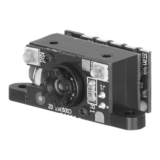
• RS 232 interface, triggering input, switching output Device construction Two integrated LEDs for illumination (red light) One integrated target LED (blue light) Center of optical axis Connector HIROSE (FH33-125-0.5SH(10)) 12-pin Mounting tabs (optional) Fig. 3.1: DCR 40 device construction Leuze electronic DCR 40... -
Page 9: Connection Technology
Device description Connection technology 12-pin HIROSE connector FH33-125-0.5Sh(10) Leuze electronic DCR 40... -
Page 10: Mounting
> 10° to avoid a total reflection of the red light beam in the case of glossy labels. γ β α α Azimuth angle β Angle of inclination γ Angle of rotation Recommended angle of rotation: γ > 10° Fig. 4.1: Definition of the reading angles Leuze electronic DCR 40... -
Page 11: Electrical Connection
TRIGGER NOTICE RS 232 polarity control Ä When unconnected, all RS 232 signals have their normal polarity. Ä When connected to GROUND, all RS232 signals have inverted polarity. Ä Do not connect RS232 signals directly to high voltage! Leuze electronic DCR 40... -
Page 12: Input / Output
Ä WAKE UP must be HIGH when the device enters the sleep mode. Otherwise, WAKE UP cannot awaken the device by asserting a LOW pulse Ä Leave the WAKE UP line open when the device is not in sleep mode. Do not tie the WAKE UP line LOW. Leuze electronic DCR 40... -
Page 13: Trigger - In
3.3 V DC 3.3 V DC max. 20 mA ! Fig. 5.2: Switching output NOTICE Maximum loading of the switching output Ä Do not load the switching output of the scan engine with more than 20 mA at 3.3 … V DC! Leuze electronic DCR 40... -
Page 14: Pc Or Terminal Connection
Status LEDs Fig. 5.3: Connection options for MA-CR modular adapter unit Cable lengths and shielding The maximum cable length is 3 m. Should a cable extension be necessary, make certain that the cables of the RS 232 interface are shielded. Leuze electronic DCR 40... -
Page 15: Configuration And Diagnostics Software - Sensor Studio
Main memory (RAM): at least 64 MB Keyboard and mouse or touchpad Graphics card At least 1024 x 768 pixels Required hard disk capacity for 35 MB Sensor Studio and communica- tion DTM NOTICE Administrator privileges on the PC are necessary for installing Sensor Studio. Leuze electronic DCR 40... -
Page 16: Installing Sensor Studio Configuration Software
• You need an RS 232 connection that establishes the RxD, TxD and GND connections between PC and device (PC or terminal connection). • The 5 V DC voltage supply is to be fed in externally (see chapter 5.1 "Voltage supply"). Leuze electronic DCR 40... -
Page 17: Starting The Sensor Studio Configuration Software
Ä Establish the online connection to the connected DCR 40. In the Sensor Studio FDT frame, click on the [Establish connection with device] button ( In the Sensor Studio FDT frame, click on the [Upload parameters to device] button ( Leuze electronic DCR 40... -
Page 18: Exiting Sensor Studio
This chapter does not include a complete description of the Sensor Studio configuration soft- ware. Complete information on the FDT frame menu and on the functions in the device manager (DTM) can be found in the online help system. Leuze electronic DCR 40... -
Page 19: Control Tab
DECODE OUTPUT OPTIONS Output Result with AIM ID Allows for the output of the AIM symbology identifier with the decode result. Barcode Prefix / Suffix enabled Enables/ disables the output of prefix and suffix text with the decode result. Leuze electronic DCR 40... -
Page 20: Decode Tab
• If there are more codes in the field of view and within target toler- ance and the device is set to decode more than one code, it will decode all codes in the field of view. • Set to 1 for fastest performance with single codes. Leuze electronic DCR 40... -
Page 21: Communications Tab
Configuration and diagnostics software - Sensor Studio Fig. 6.5: Standard settings for the Properties window (SYMBOLOGY SETTINGS) – Decode tab 6.5.3 Communications tab Fig. 6.6: Communications tab Leuze electronic DCR 40... -
Page 22: Diagnosis / Terminal
• Send online commands to the scan engine for diagnostic purposes. • Visualize the output of the scan engine. The contents of the terminal display can be printed out or saved in a file for subsequent offline evaluation. Leuze electronic DCR 40... -
Page 23: Starting Up The Device - Configuration
The setting of code type and code length is usually accomplished by using the Sensor Studio configuration software (see chapter 6 "Configuration and diagnostics software - Sensor Studio"). Leuze electronic DCR 40... -
Page 24: Configuration Control
Example: SYAZTCSPO1 This command sets the polarity to Inverse mode of the Aztec symbology and saves it to non-volatile mem- ory. Breakdown of the command: • SY = Symbology • AZTC = Aztec • S = Set • PO = Polarity • 1 = Inverse Mode Leuze electronic DCR 40... -
Page 25: Supported Commands
Example: SYAUPOSSC1 This setting value is ignored if Australian Post decoding is disabled. Aztec – Get All Parame- Returns all Aztec parameter values in an XML element. Example: SYAZTCG Aztec S/P/R/ Disable Example: SYAZTCSEN0 Enable Example: SYAZTCSEN1 Leuze electronic DCR 40... - Page 26 Note: This setting value is ignored if BC412 decoding is disabled. Canada Post S/P/R/ Disable Example: SYCAPOSEN0 Enable Example: SYCAPOSEN1 Codabar – Get All Pa- Returns all Codabar parameter values in rameter an XML element. Example: SYCBARG Leuze electronic DCR 40...
- Page 27 Example: SYCODASEN1 Codablock F S/P/R/ Disable Example: SYCODFSEN0 Enable Example: SYCODFSEN1 Code 11 – Get All Pa- Returns all code 11 parameter values in rameter an XML element. Example: SYBCO11G Code 11 S/P/R/ Disable Example: SYCO11SEN0 Enable Example: SYCO11SEN1 Leuze electronic DCR 40...
- Page 28 Example: SYCO39SCS2 Note: This setting value is ignored if Code 39 decoding is disabled. Code 39 – Extended S/P/R/ Disable ASCII On/Off Example: SYCO39SEA0 Enable Example: SYCO39SEA1 Note: This setting value is ignored if Code 39 decoding is disabled. Leuze electronic DCR 40...
- Page 29 Normal mode enabled - Black on white background Example: SYDATMSPO0 Inverse mode enabled - White on black background Example: SYDATMSPO1 Both normal and inverse modes enabled Example: SYDATMSPO2 Note: This setting value is ignored if Data Matrix decoding is disabled. Leuze electronic DCR 40...
- Page 30 Example: SYGDMXSMR0 Enable Example: SYGDMXSMR1 Note: This setting value is ignored if Grid Matrix decoding is disabled. GS1 DataBar – Get All Returns all GS1 DataBar parameter val- Parameter ues in an XML element. Example: SYGS1DG Leuze electronic DCR 40...
- Page 31 Normal mode enabled - Black on white background Example: SYHAXNSPO0 Inverse mode enabled - White on black background Example: SYHAXNSPO1 Both normal and inverse modes enabled Example: SYHAXNSPO2 Note: This setting value is ignored if Han Xin decoding is disabled Leuze electronic DCR 40...
- Page 32 Maximum Value Example: SYI2O5SLN100 Note: This setting value is ignored if Inter- leaved 2 of 5 decoding is disabled. Japan Post S/P/R/ Disable Example: SYJAPOSEN0 Enable Example: SYJAPOSEN1 KIX (Dutch Post) KIX0 S/P/R/ Disable Example: SYKIX0SEN0 Enable Example: SYKIX0SEN1 Leuze electronic DCR 40...
- Page 33 Plessey decoding is disabled. Plessey – PLE MSIP S/P/R/ Disable Example: SYMSIPSPE0 Enable Example: SYMSIPSPE1 NEC 2 of 5 – Get All Pa- Returns all NEC 2 of 5 parameter values rameter in an XML element. Example: SYN2O5G Leuze electronic DCR 40...
- Page 34 Example: SYPHCOSCB0 Enable Example: SYPHCOSCB1 Note: This setting value is ignored if Pharmacode decoding is disabled. Pharmacode – Bar S/P/R/ Minimum Value Count Min Example: SYPHCOSCN4 Note: This setting value is ignored if Pharmacode decoding is disabled. Leuze electronic DCR 40...
- Page 35 Micro QR Code S/P/R/ Disable Example: SYQRCOSMI0 Enable Example: SYQRCOSMI1 QR Code – Mirror S/P/R/ Disable Example: SYQRCOSMR0 Enable Example: SYQRCOSMR1 Note: This setting value is ignored if QR Code decoding is disabled. Leuze electronic DCR 40...
- Page 36 XML element. Example: SYTRIOG Trioptic TRIO S/P/R/ Disable Example: SYTRIOSEN0 Enable Example: SYTRIOSEN1 Trioptic – Reverse TRIO S/P/R/ Disable Example: SYTRIOSRV0 Enable Example: SYTRIOSRV1 Note: This setting value is ignored if Tri- optic decoding is disabled. Leuze electronic DCR 40...
- Page 37 Example: SYUPC0SSU1 Note: This setting value is ignored if UPC/EAN decoding is disabled. UPC/EAN – Expand S/P/R/ Disable EAN-8 to EAN-13 Example: SYUPC0S8D0 Enable Example: SYUPC0S8D1 Note: This setting value is ignored if UPC/EAN decoding is disabled. Leuze electronic DCR 40...
- Page 38 Example: SYUPC0SEC1 Note: This setting value is ignored if UPC/EAN decoding is disabled. UPC/EAN – Transmit S/P/R/ Disable UPC-E Number System Example: SYUPC0SES0 Enable Example: SYUPC0SES1 Note: This setting value is ignored if UPC/EAN decoding is disabled. Leuze electronic DCR 40...
- Page 39 Example: SYUSPLSEN0 Enable Example: SYUSPLSEN1 USPS Postnet S/P/R/ Disable Example: SYUSPOSEN0 Enable Example: SYUSPOSEN1 UPU ID Tags UPUI S/P/R/ Disable Example: SYUPUISEN0 Enable Example: SYUPUISEN1 USPS Intelligent Mail USIM S/P/R/ Disable Example: SYUSIMSEN0 Enable Example: SYUSIMSEN1 Leuze electronic DCR 40...
-
Page 40: Communications
9600 9600 Bits per second Example: CMSESBA9600 1920 19200 Bits per second Example: CMSESBA19200 3840 38400 Bits per second Example: CMSESBA38400 5760 57600 Bits per second Example: CMSESBA57600 1152 115200 Bits per second Example: CMSESBA115200 Supported Baud Rate Leuze electronic DCR 40... -
Page 41: Usb And Hid
USB – Get All parameters CM UB Returns all USB communication parame- ter values in an XML element. Example: CMUBG USB – Manufacturer CM UB S/P/R/ MF CODE A string representing the manufacturer name for the product Example: CMUBSMFCODE Leuze electronic DCR 40... - Page 42 Example: CMHDSIE2 HID Keyboard Decode Data CM HD S/P/ OM 0 Unicode as XML Lookup Output Method Example: CMHDSOM0 Unicode as Windows Alt-Se- quence Example: CMHDSOM1 Note: This parameter is only relevant when Input Conversion > 0 Leuze electronic DCR 40...
- Page 43 Polling Interval Example: CMUNSIN1000 USB VCOM – Use Serial CM UV S/P/R/ SN 0/1 Example: CMUVSSN0 Number Example: CMUVSSN1 USB HID POS – Use Serial CM UP S/P/R/ SN 0/1 Example: CMUPSSN0 Number Example: CMUPSSN1 Leuze electronic DCR 40...
-
Page 44: Packet And Protocol Parameters
In Seconds Valid Range: Example: PKOPSCT120 Reader Retry Count PK OP S/P/R/ RC 0 Number of retries from the reader when no ACK is received from the host. Valid Range: Example: PKOPSRC1 Leuze electronic DCR 40... -
Page 45: Decoder And General Decoding Parameters
CD OP S/P/R/ RW 1280 ROI width els) Region of Interest height CD OP S/P/R/ RH 960 ROI height (pixels) Low Contrast 1D CD OP S/P/R/ Disable Low Contrast Example: CDOPSLC0 Enable Low Contrast Example: CDOPSLC1 Leuze electronic DCR 40... - Page 46 Instructs the decoder to stop looking for decodes in the current image when a duplicate is found. Prefix with AIM Identifier CD OP S/P/R/ PA 0 Prefixes the decode data with the 3- character AIM identifier Leuze electronic DCR 40...
- Page 47 Enable –block duplicates for the amount of time set in DC- VAGBT Example: CDVASBD1 If enabled, the reader will not output the same barcode until the barcode has not been seen for the “duplicate block time” period. Leuze electronic DCR 40...
- Page 48 Output in upper or lower CD OP S/P/R/ upper case or bracketed hex bytes lower case hex bytes Data formatting output case/hex Example: CDOPSFC Full data format string CD OP S/P/R/ Data formatting raw format configuration string Example: CDOPSFD Leuze electronic DCR 40...
-
Page 49: Power Mode Parameters
Sleep Mode Timer Delay PM SM S/P/R/ VA 3600 If both Standby Mode Timer and Sleep (ms) Mode Timer are enabled, the device will go into Sleep Mode after this timer has expired. Valid Range: Example: PMSMSVA3600 Leuze electronic DCR 40... -
Page 50: General Reader Information
XML element Example: RDCPGRV Reader Serial Number RD CP Returns Reader Serial Number parame- ter value in an XML element Example: RDCPGSN Reader Information RD RR Returns Reader Information parameter value in an XML element Example: RDRRG Leuze electronic DCR 40... - Page 51 (see Reader Command List below) (see Reader Command List below) (see Reader Command List below) (see Reader Platform command below) RDCMX Reader Command Execute Stop decoding List Start single decode Start continuous decoding Disable Targeting Enable Targeting Leuze electronic DCR 40...
-
Page 52: Reader Configuration
Resets all reader parameters to factory Default default values. Example: CFR 8.2.9 General firmware operation Code Description Command Format Op- Notes/Examples tions fault Get All Firmware Parame- FW FW Returns all Firmware parameter values ters in an XML element. Example: FWFWG Leuze electronic DCR 40... -
Page 53: 8.2.10 General Reader Feedback Parameters
Returns all Scene Manager parameter rameters values in an XML element. Example: SCSCG Scene Manager Mode SC SP S/P/R/ MO NO Normal AGC Mode Example: SCSPSMONO Bypass AGC Mode Example: SCSPSMOBY Fixed AGC Mode Example: SCSPSMOFX Leuze electronic DCR 40... -
Page 54: 8.2.12 Setup Agc Parameters
Example: AGTMSMQ320 AGC Low Quality time limit AG TM S/P/R/ LQ 120 AGC Low Quality time limit Valid Range: Example: AGTMSLQ120 Timeout multiplier (FP24_8) AG TM S/P/R/ MT 0x100 Timeout multiplier (FP24_8) Valid Range: Example: AGTMS Leuze electronic DCR 40... -
Page 55: 8.2.13 Setup Motion Detection Parameters
Maximum gain MD PM S/P/R/ XG 47 Maximum Value Gain is the amount of signal amplifica- tion the AGC can apply to make the pic- ture easier to read Valid Range: Minimum Gain to 64 Example: MDPMSXG35 Leuze electronic DCR 40... - Page 56 (left, center, right) to be considered de- tected motion Valid Range: Example: MDPMS TL5 Detection blob threshold MD PM S/P/R/ The minimum number of sequential pix- els to be considered a group or blob (like a bar width) Valid Range: Example: MDPMSBT4 Leuze electronic DCR 40...
-
Page 57: 8.2.14 Setup Camera Parameters
• Source files can have only one Primary Category command per line (see chapter 8.1 "Configuration command architecture"). Examples: • example.crccs Contains: // Hypothetical // Outputs all settings of symbologies Aztec and Australian Post // Rev 1 – 6/22/16 – Jackson – Initial Release • example.crmkr Contains: %01%59%1d%02SYAZTCG%03SYAUPOG%03%04 • example.tif Leuze electronic DCR 40... -
Page 58: Motion Detection
Data formatting options The decoder allows many types of data formatting, selected by setting the data format option, and setting the appropriate configuration string. Leuze electronic DCR 40... - Page 59 The decoder will decode the code data. Setting the format case option changes the default configuration string. You can set the following data output options: • decoded (0) • uppercase (1) • lowercase (2) • bracketed hex (3) Example: CDOPSFC1 sets the data output in upper case. Leuze electronic DCR 40...
- Page 60 Ä Public sector validations and data formatting cannot be used at the same time. Ä When changing from the public sector validations mode to the data formatting mode, you must enter the configuration string again. Leuze electronic DCR 40...
-
Page 61: Command Protocol
0x0FFFFFFF is a special address indicating that the host device wants to broadcast to all devices on the network. Anything less than this value is a real device address. This value is written as a 4-byte big endian value. Leuze electronic DCR 40... -
Page 62: Device Acknowledgement
• Source Address • Protocol Type • Flags • Payload Protocol • Acknowledgement Number • Transaction Number • Request ID • Payload 9.1.2 Device acknowledgement Upon receipt of a command, the device immediately sends an acknowledgement. Leuze electronic DCR 40... - Page 63 Ä You must use this address in any following sequences. Without using it, the device will not respond. NOTICE The acknowledgement number in the device acknowledgement packet is the same as the trans- action number in the previous command packet. Leuze electronic DCR 40...
-
Page 64: Response Packet
Payload Protocol 0x02 Acknowledgement Num- 0x0000 Transaction Number 0x0000 Starting with zero for the transaction number. Request ID 0x8000 Following the convention, we add 0x8000 to the transaction number. Payload The bytes represent the ASCII command SYCO93PEN1. Leuze electronic DCR 40... - Page 65 Protocol Type 0x01 Flags 0x00 Payload Protocol 0x02 Acknowledgement Num- 0x0000 Transaction Number 0x8000 Request ID 0x0000 Following the convention, we add 0x8000 to the transaction number. Payload Returns <Response Val="0" Descrip- tion="none" /> CRC16 0xDA64 Leuze electronic DCR 40...
-
Page 66: Example 2: Getting Information About A Device After Startup
In this example, the host device has been communicating with the device for some time and is ready to send another command: enable Code 128 and set it as a default value. Assumptions: • Address of the host device: 0x40000000 • Address of the device: 0x01234567 Leuze electronic DCR 40... - Page 67 Start of Frame 0x01 0x43 0x54 Packet Version 0x31 Packet Length 0x000F Destination Address 0x40000000 Source Address 0x01234567 The device returns its unique address. Protocol Type 0x01 Flags 0x01 Payload Protocol 0x00 Acknowledgement Num- 0x0001 CRC16 0xFD38 Leuze electronic DCR 40...
- Page 68 Bytes (or Range) Number of Description Bytes Start of Frame 0x01 0x43 0x54 Packet Version 0x31 Packet Length 0x000F Destination Address 0x01234567 Source Address 0x40000000 Protocol Type 0x01 Flags 0x01 Payload Protocol 0x00 Acknowledgement Num- 0x8001 CRC16 0x3CEF Leuze electronic DCR 40...
-
Page 69: Barcode Decoding
• The barcode decoder takes over and sends the barcode result to the host device. The barcode result is sent in clear ASCII text, that is, without the framing protocol. • The host device sends a stop decoding command to the device. • The device sends the corresponding acknowledgement back to the host device. Leuze electronic DCR 40... -
Page 70: Care, Maintenance And Disposal
Repairs to the device must only be carried out by the manufacturer. Ä For repairs, contact your responsible Leuze electronic subsidiary or Leuze electronic customer service (see chapter 11 "Service and support"). 10.3 Disposing Ä For disposal observe the applicable national regulations regarding electronic components. Leuze electronic DCR 40... -
Page 71: Service And Support
+49 (0) 7021 573-123 Monday to Friday 8.00 a.m. to 5.00 p.m. (UTC+1) E-mail: service.identify@leuze.de Return address for repairs: Service center Leuze electronic GmbH + Co. KG In der Braike 1 D-73277 Owen / Germany 11.1 What to do should servicing be required? NOTICE Please use this chapter as a master copy should servicing be required! Ä... -
Page 72: Technical Data
(TRIGGER, WAKE UP) Switching output NPN transistor output, max. 20 mA, GOOD READ Beeper NPN transistor output, modulated, GOOD READ Tab. 12.4: Electrical equipment Operating voltage 3.3 V DC Current consumption Duration reading: typ. 350 mA, max. 450 mA Inactive illumination: typ. 75 mA Leuze electronic DCR 40... -
Page 73: Reading Fields
The origin of the read distance always refers to the front edge of the housing of the beam exit. 39.4° 130 mm 51.40° 130 mm Reading field – side view Reading field – top view Fig. 12.1: Reading field Leuze electronic DCR 40... - Page 74 65 (2.6) 175 (6.9) Data Matrix 0.127 mm (5 mil) 75 (3.0) 90 (3.5) Data Matrix 0.160 mm (6.3 mil) 70 (2.8) 135 (5.3) Data Matrix 0.254 mm (10 mil) 50 (2.0) 205 (8.1) Data Matrix 0.528 mm (20.8 mil) 30 (1.2) 425 (16.7) Leuze electronic DCR 40...
-
Page 75: Dimensioned Drawings
DCR 40 dimensioned drawing NOTICE It is advisable to use a transparent, double-sided anti-reflective coated material when installing the scan engine behind a pane of glass. Recommended pane thickness: 1 mm; optics as flush as possible with the glass. Leuze electronic DCR 40... -
Page 76: Order Guide And Accessories
PC for evaluation 50136748 DCR40-IFK DCR40 Interface Kit for use with MA-CR. Kit in- cludes: 12-pin / 6-pin Adapter cable, DCR 40 Inter- face board, Ribbon cable Sensor Studio configuration software Sensor Studio designed according to the FDT/DTM concept. Contains: communication DTM and device Download at www.leuze.com... -
Page 77: Ec Declaration Of Conformity
EC Declaration of Conformity EC Declaration of Conformity The scan engines of the DCR 40 series have been developed and manufactured in accordance with the applicable European standards and directives. Leuze electronic DCR 40... -
Page 78: Appendix
Code type 01: Interleaved 2 of 5 Module 0.3 Fig. 15.2: Code type 02: Code 39 Module 0.3 Fig. 15.3: Code type 11: Codabar Module 0.3 Fig. 15.4: Code 128 Module 0.3 Fig. 15.5: Code type 08: EAN 128 SC 2 Fig. 15.6: Code type 06: UPC-A Leuze electronic DCR 40... -
Page 79: Configuration Via Configuration Codes
SC 3 Fig. 15.7: Code type 07: EAN 8 15.2 Configuration via configuration codes The device can also be configured using configuration codes. The device parameters in the device are set and permanently saved after reading this code. Leuze electronic DCR 40... - Page 80 Prefix Space Prefix Tab (USB Keyboard Mode Prefix Tab (RS232 Mode Only) Erase Prefix Data Only) Suffix Comma Suffix Space Suffix Enter (USB Keyboard Suffix Tab (USB Keyboard Mode Mode Only) - Default Only) Fig. 15.8: Configuration Guide Leuze electronic DCR 40...
- Page 81 Aztec On - Default Symbology Settings Aztec Off Aztec Inverse & Normal On Aztec Inverse Off - Default BC412 On BC412 Off - Default Canada Post On Canada Post Off - Default Codabar On - Default Fig. 15.9: Configuration Guide Leuze electronic DCR 40...
- Page 82 Code 11 One Digit Checksum Code 11 Two Digit Checksum - Code 128 On - Default Default Code 128 Off Code 32 (Italian Pharmacode) Code 32 (Italian Pharmacode) Code 39 On - Default Off - Default Fig. 15.10: Configuration Guide Leuze electronic DCR 40...
- Page 83 Data Matrix Rectangular On - Data Matrix Rectangular Off Data Matrix Rectangular Default Extended On Data Matrix Rectangular Grid Matrix On Grid Matrix Off - Default GS1 DataBar On - Default Extended Off - Default Fig. 15.11: Configuration Guide Leuze electronic DCR 40...
- Page 84 Japan Post On Off - Default Stripped from Result On Stripped from Result Off - Default Japan Post Off - Default KIX (Dutch Post) On KIX (Dutch Post) Off - Default Korean Post On Fig. 15.12: Configuration Guide Leuze electronic DCR 40...
- Page 85 Result On from Result Off - Default Be Mod 10/11 MSI Plessey Checksum Must MSI Plessey On MSI Plessey Off - Default NEC 2 of 5 Checksum On - Be Mod 10/10 Default Fig. 15.13: Configuration Guide Leuze electronic DCR 40...
- Page 86 QR Code Mirror On QR Code Mirror Off - Default QR Code Inverse and Normal QR Code Inverse Only Telepen On Telepen Off - Default Output Telepen as Numeric - Output Telepen as ASCII Default Fig. 15.14: Configuration Guide Leuze electronic DCR 40...
- Page 87 UPC E Expansion On UPC E Expansion Off - Default Convert UPC-A to EAN-13 Do Not Convert UPC-A to Transmit UPC-A Check Digit Do Not Transmit UPC-A Check EAN-13 - Default Digit - Default Fig. 15.15: Configuration Guide Leuze electronic DCR 40...
- Page 88 Transmit EAN-13 Check Digit Do Not Transmit EAN-13 Check Digit - Default Digit - Default UPU ID Tags On UPU ID Tags Off - Default USPS Intelligent Mail On USPS Intelligent Mail Off - Default Fig. 15.16: Configuration Guide Leuze electronic DCR 40...
- Page 89 Swiss Keyboard Mapping for Windows Keyboard Support: Italian Keyboard Support: Japanese Keyboard Support: Russian Keyboard Support: Spanish-Latin Keyboard Mapping for Apple Keyboard Mapping for Windows Keyboard Mapping for Windows American Keyboard Mapping for Windows Fig. 15.17: Configuration Guide Leuze electronic DCR 40...
- Page 90 RS232 Interface - 2400 Baud Defaults Rate Rate RS232 Settings RS232 Interface - 4800 Baud RS232 Interface - 9600 Baud RS232 Interface - 19200 Baud RS232 Interface - 38400 Baud Rate Rate Rate Rate Fig. 15.18: Configuration Guide Leuze electronic DCR 40...
- Page 91 Default Default Scan Delay Settings Set Duplicate Scan delay to 1 Set Duplicate Scan delay to 2 Set Duplicate Scan delay to 3 Set Duplicate Scan delay to 5 Second Seconds Seconds Seconds Fig. 15.19: Configuration Guide Leuze electronic DCR 40...
- Page 92 Reader/Modem Command Settings Reset to Factory Defaults Intentionally Blank Intentionally Blank Reset, Clear and Save Reader Settings Intentionally Blank Intentionally Blank Intentionally Blank Intentionally Blank Intentionally Blank Intentionally Blank Intentionally Blank Intentionally Blank Fig. 15.20: Configuration Guide Leuze electronic DCR 40...