Table of Contents
Advertisement
Quick Links
Advertisement
Table of Contents

Subscribe to Our Youtube Channel
Related Manuals for Datcon PQRM5300 33 U I Series


Summary of Contents for Datcon PQRM5300 33 U I Series
-
Page 1: Power Network With Neutral Conductor
PQRM5300 33 Ux Ix xx xx (PS) Three-phase Power Meter Instruction manual... -
Page 2: Table Of Contents
PQRM5300 33 Ux Ix xx xx (PS) Contents 1. About this document............5 1.1. Function ................... 5 1.2. Target group................5 1.3. Symbolism used............... 5 2. For your safety..............6 2.1. Authorized personnel ............... 6 2.2. Appropriate use................ 6 2.3. Warning about misuse ............. 6 2.4. -
Page 3: Phase Measurement With Neutral Conductor
PQRM5300 33 Ux Ix xx xx (PS) 5.5. Connecting the measuring inputs to medium voltage power network. Three phase measurement without neutral conductor. (3 phase, 3 wire, 3 measuring)............19 5.6. Connecting the measuring inputs to symmetrical three-phase power network with neutral conductor. (3 phase, 4 wire, 1 measuring) .................. - Page 4 PQRM5300 33 Ux Ix xx xx (PS) 7.3. Configurations menu .............. 42 7.3.1 Measure input settings ............43 7.3.1.1. Measure configuration............43 7.3.1.2. Voltage Transformers (VT) and Current Transformers (CT) ratio settings................. 45 7.3.1.3. Phase lag of CT settings ..........46 7.3.1.4.
-
Page 5: About This Document
PQRM5300 33 Ux Ix xx xx (PS) 1. About this document 1.1. Function This operating instructions manual has all the information you need for quick set-up and safe operation of PQRM5300 33 Ux Ix xx xx (PS). Please read this manual before you start setup. 1.2. -
Page 6: For Your Safety
For safety and warranty reasons, any internal work on the instruments must be carried out only by DATCON personnel. 2.2. Appropriate use The PQRM5300 33 Ux Ix xx xx (PS) is a Three-phase Power Meter. -
Page 7: Product Description
PQRM5300 33 Ux Ix xx xx (PS) 3. Product description 3.1. Delivery configuration Delivered items The scope of delivery encompasses: • PQRM5300 33 Ux Ix xx xx (PS) • documentation: this operating instructions certification warranty 3.2. Type designation 20201120-V1... -
Page 8: Operating Principle
PQRM5300 33 Ux Ix xx xx (PS) 3.3. Operating principle Area of application A PQRM5300 33 Ux Ix xx xx (PS) Three-phase Power Meter measure the characteristic for three-phase network system. The measured values are displayed on a graphic display, and they are forward for processing units. Programming and adjustment are performed via the front panel membrane keypad. - Page 9 PQRM5300 33 Ux Ix xx xx (PS) Measuring parameters: Per phase: • : Measured voltage of L1, L2, L3 phase [V] • : Measured current of L1, L2, L3 phase [A] • P: Measured active power of L1, L2, L3 phase [W] •...
-
Page 10: Display, Indicators, Keyboard
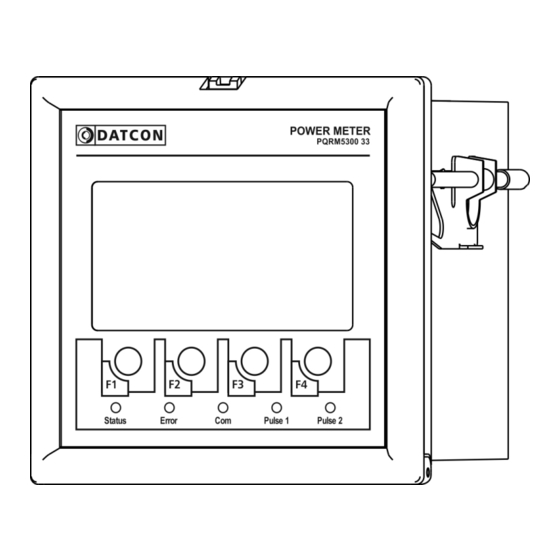
PQRM5300 33 Ux Ix xx xx (PS) 3.4. Display, Indicators, keyboard The following figure shows the instruments front: 1. Monochrome graphic LCD to displaying the measured value, menu points and the error messages. 2. Membrane keypad for navigation in the menu system, selection for the menu items and entering numeric values (F1-F4) 3. -
Page 11: Storage And Transport
PQRM5300 33 Ux Ix xx xx (PS) 3.5. Storage and transport This instrument should be stored and transport in places whose climatic conditions are in accordance with chapter 10.1. Technical specification as described under the title: Environmental conditions. The packaging of instrument consist of environment- friendly, recyclable cardboard is used to protect the instrument against the impacts of normal stresses occurring during transportation. -
Page 12: Mounting
PQRM5300 33 Ux Ix xx xx (PS) 4. Mounting 4.1. General instructions Use the enclosed seal between the instrument and the panel when mounting the instrument to assure IP 54 from the front. The instrument should be installed in a cabinet with sufficient IP protection, where the operating conditions are in accordance with chapter 10.1. -
Page 13: Mounting
PQRM5300 33 Ux Ix xx xx (PS) 4.3. Mounting Preparatory steps The following figure shows the dimensions of panel cut-out: (thickness: 2 - 5 mm) Dimensions of panel cutout 1. Cut-out the panel according to the figure shows above. The cut-out needs special tools, it must be carried out by trained specialist personnel. - Page 14 PQRM5300 33 Ux Ix xx xx (PS) Before fitting the instrument into the panel cut-out it is recommended to exercise the using of mounting clamps. Put the instrument onto a table and follow the steps (from step 2.) written under the figure: Mounting with the mounting clamps Please do not exercise forces higher than necessary, as it...
-
Page 15: Connecting
PQRM5300 33 Ux Ix xx xx (PS) 5. Connecting 5.1. Preparing the connection Always observe the following safety instructions: • The connection must be carried out by trained and authorized personnel only • Connect only in the complete absence of supply voltage •... -
Page 16: Connecting The Measuring Inputs To Power Network. Three
PQRM5300 33 Ux Ix xx xx (PS) 5.2. Connecting the measuring inputs to power network. Three phase measurement with neutral conductor. (3 phase, 4 wire, 3 measuring) The following figure shows the wiring plan, connecting the instrument to low voltage power network with neutral conductor. -
Page 17: Connecting The Measuring Inputs To Power Network. Three Phase Measurement Without Neutral Conductor. (3 Phase, 3 Wire, 3 Measuring)
PQRM5300 33 Ux Ix xx xx (PS) 5.3. Connecting the measuring inputs to power network. Three phase measurement without neutral conductor. (3 phase, 3 wire, 3 measuring) The following figure shows the wiring plan, connecting the instrument to low voltage power network without neutral conductor. -
Page 18: Connecting The Measuring Inputs Trough Transformer To Power Network. Three Phase Measurement With Neutral Conductor. (3 Phase, 4 Wire, 3 Measuring)
PQRM5300 33 Ux Ix xx xx (PS) 5.4. Connecting the measuring inputs trough transformer to power network. Three phase measurement with neutral conductor. (3 phase, 4 wire, 3 measuring) The following figure shows the wiring plan, connecting the instrument to medium voltage power network with neutral conductor. -
Page 19: Connecting The Measuring Inputs To Medium Voltage Power
PQRM5300 33 Ux Ix xx xx (PS) 5.5. Connecting the measuring inputs to medium voltage power network. Three phase measurement without neutral conductor. (3 phase, 3 wire, 3 measuring) The following figure shows the wiring plan, connecting the instrument to medium voltage power network without neutral conductor Wiring plan, connecting the voltage and current... -
Page 20: Measuring)
PQRM5300 33 Ux Ix xx xx (PS) to symmetrical 5.6. Connecting the measuring inputs three-phase power network with neutral conductor. (3 phase, 4 wire, 1 measuring) The following figure shows the wiring plan to symmetrical three-phase network. Measuring only one phase. The three phase outputs are calculated values. -
Page 21: Connecting The Measuring Inputs To Symmetrical Three-Phase Power Network Without Neutral Conductor. (3 Phase, 3 Wire, 1 Measuring)
PQRM5300 33 Ux Ix xx xx (PS) to symmetrical 5.7. Connecting the measuring inputs three-phase power network without neutral conductor. (3 phase, 3 wire, 1 measuring) The following figure shows the wiring plan to symmetrical three-phase network without neutral conductor. Measuring only one phase. -
Page 22: Aron Mode (3 Phase, 3 Wire, 2 Measuring)
PQRM5300 33 Ux Ix xx xx (PS) 5.8. Aron mode (3 phase, 3 wire, 2 measuring) The following figure shows the wiring plan to three-phase network without neutral conductor with two measuring input. The three phase outputs are calculated values. Wiring plan, connecting the voltage and current inputs to power network. -
Page 23: Connecting The Measuring Inputs To Three-Phase Power Network Trough Three-Phase Voltage Transformers Without Common Connection Point (3 Phase, 3 Wire, 3 Measuring, 3Fmv)
PQRM5300 33 Ux Ix xx xx (PS) to three-phase 5.9. Connecting the measuring inputs power network trough three-phase voltage transformers without common connection point (3 phase, 3 wire, 3 measuring, 3fmv) The following figure shows the wiring plan to three-phase network without neutral conductor. -
Page 24: Connecting The Digital Outputs
PQRM5300 33 Ux Ix xx xx (PS) 5.10. Connecting the digital outputs The digital outputs of the device are passive switch transistor. The external power supply is required for operation. The figure shows the outputs terminal of the switching transistor Output terminal of the digital outputs The technical parameters of the digital outputs refer to the... - Page 25 PQRM5300 33 Ux Ix xx xx (PS) Example: Connect the digital output for processing unit. Wiring plan, connecting to processing unit. Be careful the polarity of the cables! 1. Loosen terminal screws. 2. Insert the wire ends into the open terminals according to the wiring plan.
-
Page 26: Connecting To Modbus Rs485 Network
PQRM5300 33 Ux Ix xx xx (PS) 5.11. Connecting to MODBUS RS485 network The following figure shows the wiring plan, connecting the devices with MODBUS RS485 option to processing unit. Wiring plan, connecting to processing unit. Be careful the polarity of the cables! 1. -
Page 27: Connecting To Ethernet Network
PQRM5300 33 Ux Ix xx xx (PS) 5.12. Connecting to ETHERNET network The following figure shows the wiring plan, connecting the devices with ETHERNET option to processing unit. Wiring plan, connecting to processing unit. 1. Connect the ETHERNET cable to RJ45 socket, which located on the backplane of the device. -
Page 28: Connecting The Analog Output To Signal Processing Unit
PQRM5300 33 Ux Ix xx xx (PS) 5.13. Connecting the analog output to signal processing unit The following figure shows the wiring plan, connecting the devices with Analog output option to processing unit. Wiring plan, connecting the analog output to the signal processing unit Be careful the polarity of the cables! -
Page 29: Connecting The Power Supply
PQRM5300 33 Ux Ix xx xx (PS) 5.14. Connecting the power supply The following figure shows the wiring plan, connecting the PQRM5300 33 Ux Ix xx xx to the power supply: Wiring plan, connecting the power supply In case of DC supply the polarity is indifferent 1. -
Page 30: Setting - Up
PQRM5300 33 Ux Ix xx xx (PS) 6. Setting – up 6.1. First steps If you turned on the devices, you can see on display the Main menu. The bottom line of the display you can read the function of F1, F2, F3, F4 buttons. This line shows always the current functions the buttons. -
Page 31: Main Menu, Measured Data
PQRM5300 33 Ux Ix xx xx (PS) 6.2. Main menu, Measured data Here you can select to display the measured values. 1.1. L1 phase 1.2. L2 phase 1.3. L3 phase 1.4. L1 L2 L3 phases 1.5. User display 1 1.6. User display 2 The following measured values are displayed in menu L1 phase, L2 phase, L3 phase •... - Page 32 PQRM5300 33 Ux Ix xx xx (PS) • THD U (Calculated total harmonic distortion of phase voltage (up to 19. harmonic ) [%] • THD I (Calculated total harmonic distortion of phase current (up to 19. harmonic ) [%] The device desplayed the following network data in the L1 L2 L3 phases submenu: •...
-
Page 33: Main Menu, Energy Menu
PQRM5300 33 Ux Ix xx xx (PS) 6.3. Main menu, Energy menu Menu items and their meaning: 2.1. L1 energy 2.2. L2 energy 2.3. L3 energy 2.4. Energy sum The individual menu items are displayed as a measured value: • +E (Measured values of consument active energy), •... -
Page 34: Main Menu, Power Limit
PQRM5300 33 Ux Ix xx xx (PS) 6.6. Main menu, Power limit The device calculates the expected average performance (15 min) from actual power. If this value is greater than the setting limit, the device set to active state the digital1 output. -
Page 35: Main Menu, User Settings Menu
PQRM5300 33 Ux Ix xx xx (PS) If the sync pulse is out, the following massage are readable on display: “Syncronpulse out!” “Unexpected syncronpulse!” Press the BACK button to return to the menu. 6.7. Main menu, User settings menu In this menu, you can set parameters for display. Here you can edit the custom display images, and can you set display brightness and backlight intensity. -
Page 36: Settings
PQRM5300 33 Ux Ix xx xx (PS) 7. Settings 7.1. General information After you turn on the device, you can see in the display the Main menu or the last selected menu. In last line of display show the function of soft buttons (F1, F2, F3, F4). First step change please the display backlight intensity in 6.2. -
Page 37: Required Settings
PQRM5300 33 Ux Ix xx xx (PS) 7.1.1. Required settings After first power up the device is in working condition. In this case the device working in factory settings. For proper operation, the following settings may be required: • 7.1.1. Measure configuration Here you can set the measuring arrangement. -
Page 38: Entering Numbers (Editing Numbers)
PQRM5300 33 Ux Ix xx xx (PS) 7.1.2. Entering numbers (Editing numbers) When you would like editing the number, you can see the following window: The editing number name and his unit are in the first line. The number is in the third line. The cursor marks the current local value. -
Page 39: Enter To User Settings Menu
PQRM5300 33 Ux Ix xx xx (PS) 7.2. Enter to User settings menu Entering to submenu Move with the / buttons in the Main menu, and select the 6. User setting menu. Press the ENTE switch. Submenu of User Submenu of 6. -
Page 40: Setting The Brightness Of Displaybacklight
PQRM5300 33 Ux Ix xx xx (PS) 7.2.2. Setting the brightness of displaybacklight Function In the 6.2. Screen settings menu can you set the brightness of display. Here you can set again the backlight active time and the standby light level. The brightness of display is 100% in active mode. -
Page 41: Editing The User Displays
PQRM5300 33 Ux Ix xx xx (PS) 7.2.3. Editing the user displays Function The device has two special displays. These displays are editable from user. This displays show just the measure result of the network. You can edit these displays in the menu 6.3. -
Page 42: Configurations Menu
PQRM5300 33 Ux Ix xx xx (PS) 7.3. Configurations menu Entering in the menu 1. Choose the 7 Configurations menu of the Main menu with / buttons, and press the ENTE switch. 2. Please type the password with help , - , + switches, and press the OK switch to accept the value. -
Page 43: Measure Input Settings
PQRM5300 33 Ux Ix xx xx (PS) 7.3.1 Measure input settings Function In the 7.1 Measure configurations menu you can set the how connect the device to network. Here you can set the voltage and currents transformers for inputs (if they are usable) and other special parameters of the measurement. - Page 44 PQRM5300 33 Ux Ix xx xx (PS) Sequence of operations 1. Log in the 7. Configurations menu 2. Choose the 7.1. Measure settings menu of the 7. Configurations menu with / buttons, and press the ENTE switch. 3. Choose the 7.1.1. Measure configurations menu of the 7.1 Measure settings menu with ...
-
Page 45: Voltage Transformers (Vt) And Current Transformers (Ct) Ratio Settings
PQRM5300 33 Ux Ix xx xx (PS) 7.3.1.2. Voltage Transformers (VT) and Current Transformers (CT) ratio settings Function In the 7.1.2. Transformations menu can you set the ratio of Voltage and Currents transformers The voltage inputs of the instrument may connect directly to the power network (Vin <... -
Page 46: Phase Lag Of Ct Settings
PQRM5300 33 Ux Ix xx xx (PS) 7.3.1.3. Phase lag of CT settings Function If you know the phase shift (50Hz) of the current transformer, you can specify the value here. The device to compensate the measurement results. [Default: 0.] Sequence of operations 1. -
Page 47: Sampling Time Setting
PQRM5300 33 Ux Ix xx xx (PS) 7.3.1.4. Sampling time setting Function The device sampling the necessary data for the calculation. If the sampling time goes out (minimum 80 ms) the MCU of device makes the calculations and updates the outputs. You can increase the sampling time. -
Page 48: Current Threshold
PQRM5300 33 Ux Ix xx xx (PS) 7.3.1.5. Current threshold Function When the current threshold function is used on the current input, the instrument eliminates the input signal under x% of the input range. This function may be useful when the power network is noisy either in voltage off state or in unloaded state and this effect may cause an error in energy measurement. -
Page 49: Setting The Optional Modules
PQRM5300 33 Ux Ix xx xx (PS) 7.4. Setting the optional modules Function You can set here the modules (analogue output, communication output, digital inputs and digital outputs) The modules are available in 7.2. Modul #1 settings and 7.3. Modul #2 settings submenus. Warning! If you can not enter to the submenu, the module is unaviable. -
Page 50: Digital Output, Energy Pulse Output Settings
PQRM5300 33 Ux Ix xx xx (PS) 7.4.1.1. Digital output, Energy pulse output settings Function The instrument has two open collector transistor pulse outputs for transmitting export-import energy values for data acquisition purposes. The frequency of the pulse outputs is proportional to the measured energy. - Page 51 PQRM5300 33 Ux Ix xx xx (PS) 16. Select from the menu with switch the output polarity. When you select the “NO (Normally open)” state then the output transistor is in off state when there is no pulse on the output.
-
Page 52: Digital Output, Energy Sign Output Settings
PQRM5300 33 Ux Ix xx xx (PS) 7.4.1.2. Digital output, Energy sign output settings Function The instrument can transmit the energy sign on the Pulse outputs. + sign: energy export - sign: energy import Here you can select the output for transmitting sign, the energy (E ) and the polarity of the output. -
Page 53: Digital Output, Limit Output Settings
PQRM5300 33 Ux Ix xx xx (PS) Digital output, Limit output settings 7.4.1.3. Function Here you can set low limit-, high limit values and hysteresis and assign them to any measured quantity. The instrument compares continuously this quantity to the measured value and activates digital output(s) according the output settings. - Page 54 PQRM5300 33 Ux Ix xx xx (PS) “Signal high limit” The output changes into active state when measured value becomes higher as the monitored value. The output changes into inactive state when measured value become lower as the monitored value and hysteresis “Signal inside limit”...
- Page 55 PQRM5300 33 Ux Ix xx xx (PS) “Signal outside limit” The output changes into active state when measured value is out upper and lower limit as the monitored value. The output changes into inactive state when measured value is between of range upper and lower limit as the monitored value.
-
Page 56: Digital Output, Alarm Output Settings
PQRM5300 33 Ux Ix xx xx (PS) Digital output, Alarm output settings 7.4.1.4. Function The instrument can generate alarm signaling in a case of one or more errors. It can be select which errors generate the alarm signaling. The alarm state activates the digital outputs. -
Page 57: Digital Output, Demand Control Function Setting
PQRM5300 33 Ux Ix xx xx (PS) 7.4.1.5. Digital output, Demand control function setting Function The device calculates the expected average performance (15 min) from actual power. If this value is greater than the setting limit, the device set to active state the digital1 output. If the value is lower than the limit at the next sampling, the device turn back the digital1 output. - Page 58 PQRM5300 33 Ux Ix xx xx (PS) Sequence of operations 1. Log in the 7. Configurations menu 2. Choose the 7.2. Modul #1 settings menu of the 7. Configurations menu with / buttons, and press the ENTE switch. 3.
-
Page 59: Digital Output, Digital Output Test
PQRM5300 33 Ux Ix xx xx (PS) 7.4.1.6. Digital output, digital output test Function Digital outputs can be tested regardless of their function, This function you can easier to detect the connections, cables, and fault I / O modules. Sequence of operations 1. Log in the 7. Configurations menu 2. -
Page 60: Analogue Output Settings
PQRM5300 33 Ux Ix xx xx (PS) 7.4.2. Analogue output settings Function There can be two optional dual independent analog outputs of the instrument. Any of the measured quantities can be transmit in a 0 / 4-20 mA current form. Here you can set all of the parameters of the outputs. -
Page 61: Analogue Output Testing
PQRM5300 33 Ux Ix xx xx (PS) 7.4.2.1. Analogue output testing Function You can here testing the analouge outputs. Sequence of operations 1. Log in the 7. Configurations menu 2. Choose the 7.2. Modul #2 settings menu of the 7. Configurations menu with / buttons, and press the ENTE switch. - Page 62 PQRM5300 33 Ux Ix xx xx (PS) Attention! If "Test value" position leaves the 'Select' window, the analog output will not change the current output. Example: Setting analog output Type 4–20mA Mode Error mode Min. 3.800 mA Max. 20.100 mA Error 20.500 mA Select...
-
Page 63: Communication Interface
PQRM5300 33 Ux Ix xx xx (PS) 7.4.3. Communication interface 7.4.3.1. MODBUS RS485 interface setting Function It can be read out through the communication output all of the measured quantities. The optional communication option have two operating mode: • MODBUS RTU Slave RS485 •... -
Page 64: Modbus Tcp Ethernet Interface Setting
PQRM5300 33 Ux Ix xx xx (PS) 18. Choose the Time out menu with / buttons, and press the ENTE switch. 19. Type the response timeout of instrument value with help , - , + switches, and press the OK switch to accept the value. -
Page 65: Modbus Registers Format
PQRM5300 33 Ux Ix xx xx (PS) 7.4.3.3 MODBUS registers format The range of measured vale is 1000-7531 address, and they are readable with 3 Modbus command. • The 1000–1067, 1132–1143, 1304–1327, 2000–2015, 2034–2037, 3000–3015, 3034–3037, 4000–4015, 4034– 4037, 4096–4155, 4162–4167, 5000–5009, 6000–6015 of the measured quantities are in 32 bit “Single Precision”... - Page 66 PQRM5300 33 Ux Ix xx xx (PS) MODBUS address All measured value Content Content addr. addr. 1000 U high 16 bit 1001 U low 16 bit eff 12 eff 12 1002 U high 16 bit 1003 U low 16 bit eff 23 eff 23 1004 U...
- Page 67 PQRM5300 33 Ux Ix xx xx (PS) Content Content addr. addr. 1072 +E 63–48 bit 1073 +E 47–32 bit 1074 +E 31–16 bit 1075 +E 15–0 bit 1076 +E 63–48 bit 1077 +E 47–32 bit 1078 +E 31–16 bit 1079 +E 15–0 bit 1080 -E 63–48 bit...
- Page 68 PQRM5300 33 Ux Ix xx xx (PS) Serial number, Nominal voltave, Nominal current, Voltage ratio, Current ratio Content Content addr. addr. 1300 Serial number high 1301 Serial number low 16 bit 16 bit 1302 Manufacturing year 1303 Installed options and month 1304 U high 16 bit 1305 U...
- Page 69 PQRM5300 33 Ux Ix xx xx (PS) L1 phase value Content Content addr. addr. 2000 U high 16 bit 2001 U low 16 bit eff 1 eff 1 2002 I high 16 bit 2003 I low 16 bit eff 1 eff 1 2004 P high 16 bit...
- Page 70 PQRM5300 33 Ux Ix xx xx (PS) L2 phase value Content Content addr. addr. 3000 U high 16 bit 3001 U low 16 bit eff 2 eff 2 3002 I high 16 bit 3003 I low 16 bit eff 2 eff 2 3004 P high 16 bit...
- Page 71 PQRM5300 33 Ux Ix xx xx (PS) L3 phase value Content Content addr. addr. 4000 U high 16 bit 4001 U low 16 bit eff 3 eff 3 4002 I high 16 bit 4003 I low 16 bit eff 3 eff 3 4004 P high 16 bit...
- Page 72 PQRM5300 33 Ux Ix xx xx (PS) Custom register range Content Content addr. addr. 4096 U high 16 bit 4097 U low 16 bit eff average eff average 4098 U high 16 bit 4099 U low 16 bit eff 1 eff 1 4100 U high 16 bit...
- Page 73 PQRM5300 33 Ux Ix xx xx (PS) Three phase value Content Content addr. addr. 5000 ∑P high 16 bit 5001 ∑P low 16 bit 5002 ∑Q high 16 bit 5003 ∑Q low 16 bit 5004 ∑S high 16 bit 5005 ∑S low 16 bit 5006 ∑PF high 16 bit 5007 ∑PF low 16 bit 5008 ∑Fi high 16 bit...
- Page 74 PQRM5300 33 Ux Ix xx xx (PS) Powers, Energies (readable as 32 bit value) Content Content addr. addr. 6000 P high 16 bit 6001 P low 16 bit 6002 Q high 16 bit 6003 Q low 16 bit 6004 P high 16 bit 6005 P low 16 bit...
- Page 75 PQRM5300 33 Ux Ix xx xx (PS) Energies (kWh, kVARh) Content Content addr. addr. 7000 +E 63–48 bit 7001 +E 47–32 bit 7002 +E 31–16 bit 7003 +E 15–0 bit 7004 +E 63–48 bit 7005 +E 47–32 bit 7006 +E 31–16 bit 7007 +E 15–0 bit...
- Page 76 PQRM5300 33 Ux Ix xx xx (PS) Energies (MWh, MVARh) Content Content addr. addr. 7100 +E 63–48 bit 7101 +E 47–32 bit 7102 +E 31–16 bit 7103 +E 15–0 bit 7104 +E 63–48 bit 7105 +E 47–32 bit 7106 +E 31–16 bit 7107 +E 15–0 bit...
- Page 77 PQRM5300 33 Ux Ix xx xx (PS) Energies (GWh, GVARh) Content Content addr. addr. 7200 +E 63–48 bit 7201 +E 47–32 bit 7202 +E 31–16 bit 7203 +E 15–0 bit 7204 +E 63–48 bit 7205 +E 47–32 bit 7206 +E 31–16 bit 7207 +E 15–0 bit...
- Page 78 PQRM5300 33 Ux Ix xx xx (PS) Energies (kWh, kVARh) (32 bit!) Content Content addr. addr. 7300 +E 31–16 bit 7301 +E 15–0 bit 7302 +E 31–16 bit 7303 +E 15–0 bit 7304 +E 31–16 bit 7305 +E 15–0 bit 7306 -E 31–16 bit 7307 -E...
- Page 79 PQRM5300 33 Ux Ix xx xx (PS) Energies (GWh, GVARh) (32 bit!) Tartalom Tartalom addr addr 7500 +E 31–16 bit 7501 +E 15–0 bit 7502 +E 31–16 bit 7503 +E 15–0 bit 7504 +E 31–16 bit 7505 +E 15–0 bit 7506 -E 31–16 bit 7507 -E...
-
Page 80: Error Led Settings
PQRM5300 33 Ux Ix xx xx (PS) 7.5. Error LED settings Function The error indicator LED is set when the error indication is enabled in 7.5 Error LED setting menu. The errors are stored in the memory, and can be viewed in 5. Errors menu. In 5. -
Page 81: Clear Errors
PQRM5300 33 Ux Ix xx xx (PS) Error messages Error Explanation: number: Calibration values are demaged User settings are demaged Saved energies are demaged Voltage dip: The voltage value is less than 90% of nominal value. (Not used the EN50160 standart) Voltage interrupt: The voltage value is less than 10% of nominal value. -
Page 82: Clear The Energyregisters
PQRM5300 33 Ux Ix xx xx (PS) 7.7. Clear the Energyregisters Function Here can the Supervisor delete the energy regesiters. You can not write back the previous value! Sequence of operations 1. Log in the 7. Configurations menu 2. Choose the 7.7. Clear energy menu of the 7. -
Page 83: Fault Rectification
Ix xx xx (PS) is defective call the manufacturer service department. 8.2. Repairing There is no user repairable part inside the instrument. In accordance with Point 2.1.: For safety and warranty reasons, any internal work on the instrument must be carried out by DATCON personnel. 20201120-V1... -
Page 84: Dismounting
PQRM5300 33 Ux Ix xx xx (PS) 9. Dismounting 9.1. Dismounting procedure Before dismounting take note the warnings written in Chapter 5.1. The following figure shows the dismounting procedures: Dismounting from the rail The dismounting procedure needs a screwdriver for slotted screws. -
Page 85: Disposal
PQRM5300 33 Ux Ix xx xx (PS) 9.2. Disposal According with the concerning EU directive, the manufacturer undertakes the disposal of the instrument that are manufactured by it and intended to be destroyed. Please deliver it in contamination-free condition to the site of the Manufacturer or to a specialized recycling company. -
Page 86: Appendix
PQRM5300 33 Ux Ix xx xx (PS) 10. Appendix 10.1. Technical specification Safety data: The connection terminals of the inputs, the outputs and the supply voltages are galvanic isolated from each other. The isolation of the measuring inputs and the power supply input are in accordance with the standard MSZ EN 61010-1, taking into consideration the following: Pollution level:... - Page 87 PQRM5300 33 Ux Ix xx xx (PS) Output parameters: The device has one analogue option or one communication option at same time. MODBUS communication interface (optional): RS485 Interface type: RS485, galvanic isolated Baud rate: 300 / 600 / 1200 / 2400 / 4800 / 9600 / 14400 / 19200 / 32800 / 56000 / 57600 / 115200 Baud Parity:...
- Page 88 PQRM5300 33 Ux Ix xx xx (PS) Power supply: Supply voltage: 24 VDC ±10% PQRM5300 33 Ux Ix xx xx vagy 230 V AC/DC ±10% PQRM5300 33 Ux Ix xx xx PS Power consumption: 1.5 VA / 1 W Galvanic isolation: Operating isolation voltage: 250 Veff (between measuring inputs and power supply input)
- Page 89 PQRM5300 33 Ux Ix xx xx (PS) Electromagnetic compatibility (EMC) In accordance with the standard MSZ EN 61326-1 Emission: In accordance with the standard MSZ EN 61326-1 Conducted: MSZ EN 55011 Limits for Class A equipments Radiated: MSZ EN 55011 Limits for Class A equipments ESD: 4 kV/8 kV contact / air...
-
Page 90: Modbus Rs485 Bus Topology
PQRM5300 33 Ux Ix xx xx (PS) MODBUS RS485 bus topology 10.2. 20201120-V1... -
Page 91: Ethernet Network Topology
PQRM5300 33 Ux Ix xx xx (PS) Ethernet network topology 10.3. 20201120-V1...
Need help?
Do you have a question about the PQRM5300 33 U I Series and is the answer not in the manual?
Questions and answers