Table of Contents
Advertisement
Quick Links
Advertisement
Table of Contents

Related Manuals for Datcon DT4227 UI


Summary of Contents for Datcon DT4227 UI
- Page 1 DT4227 UI (PS) Process Indicator Operating Instructions...
-
Page 2: Table Of Contents
DT4227 UI (PS) Contents . About this document..............4 1.1. Function....................4 1.2. Target group..................4 1.3. Symbolism used .................. 4 2. For your safety................5 2.1. Authorized personnel................5 2.2. Appropriate use ................... 5 2.3. Warning about misuse ................. 5 2.4. General safety instructions ..............5 2.5. - Page 3 DT4227 UI (PS) Setting-up................20 7.1. Functions of the push-buttons during navigation in the menu .... 20 7.2. Typing the code (password) in............21 7.3. The menu structure ................22 7.4. The menu structure (detailed description).......... 23 7.5. Menu item 01: Display brightness............24 7.6.
-
Page 4: About This Document
DT4227 UI (PS) 1. About this document start 1.1. Function This operating instructions manual has all the information you need for quick set-up and safe operation of instrument. Please read this manual before you start setup. 1.2. Target group This operating instructions manual is directed to trained personnel. -
Page 5: For Your Safety
2.5. CE conformity A DT4227 UI is in conformity with the provisions of the following standards: MSZ EN 61326-1 (EMC) 2.6. Environmental instructions Protection of the environment is one of our most important duties. -
Page 6: Product Description
3.2. Type designation 3.3. Operating principle Area of application The DT4227 UI (PS) Process Indicator enable process variable 0-20 mA, 4-20 mA, 0-10 V, 0-5 V, 2-10 V to be displayed in engineering units ont he control panel. Any optional display range can be assigned to the input signal range. -
Page 7: Adjustment
DT4227 UI (PS) 3.4. Adjustment The instrument can be adjusted through the 3 button front panel keypad. All configuration parameters are stored in the instrument FRAM for unlimited time, even when the supply voltage being switched off. The instrument doesn't need any internal adjustment. -
Page 8: Mounting
DT4227 UI (PS) 4. Mounting 4.1. General instructions Mounting position Select a mounting position you can easily read the display reach for mounting and connecting the instrument and that minimizes the hazard of water, dust or dump getting into the instrument. - Page 9 DT4227 UI (PS) Mounting with the mounting clamps 1. Put the instrument into the prepared cut-out until it possible and check the fitting of the seal between case and mounting surface. 2. Place the retaining tabs on the copper pins on the side of the unit.
-
Page 10: Connecting
DT4227 UI (PS) 5. Connecting 5.1. Preparing the connection Always observe the following safety instructions: • Connect or disconnect only in the complete absence of line voltage • Take note the data concerning on the overcurrent protection in installation. •... -
Page 11: Connecting The Mains
DT4227 UI (PS) 5.2. Connecting the mains The following figure shows the wiring plan, connecting the a DT4227 UI PS type instrument to the mains: Wiring plan, connecting the PS type instrument to the mains In case of DC supply the polarity is indifferent. - Page 12 DT4227 UI (PS) The following figure shows the wiring plan, connecting the DT4227 UI instrument to the low voltage power supply: Wiring plan, connecting the 24 V type instrument to the the low voltage power supply In case of DC supply the polarity is indifferent.
-
Page 13: Connecting To Active Current Transmitter
DT4227 UI (PS) 5.3. Connecting to active current transmitter The following figure shows the wiring plan: Wiring plan 1. Pull out the terminal so you can make connection easier. 2. Loosen terminal screws. 3. Insert the wire ends into the open terminals according to the wiring plan. -
Page 14: Connecting To Voltage Transmitter
DT4227 UI (PS) 5.4. Connecting to voltage transmitter The following figure shows the wiring plan: Wiring plan 1. Pull out the terminal so you can make connection easier. 2. Loosen terminal screws. 3. Insert the wire ends into the open terminals according to the wiring plan. -
Page 15: Display And Manual Controls
DT4227 UI (PS) 6. Display and manual controls 6.1. The first start-up The factory default setting is: Selected input signal: 4-20 mA Scaling: 4 mA ÷ 20 mA ÷ 100% When the input current is 0 mA, you can see . on the display. -
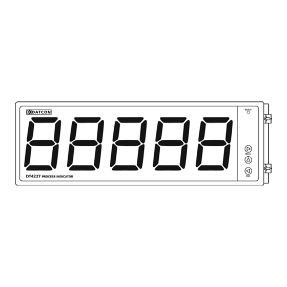
Page 16: Characters And Mnemonics Appearing On The Display
DT4227 UI (PS) 6.2. Characters and mnemonics appearing on the display DT4227 UI has a 7-segment type display. It means that maximum 7 bars are used to form each characters. The numbers can be read easily, some of the letters, marks however, looks unusual: ... - Page 17 DT4227 UI (PS) Login text DT - Datcon instrument. Type of the instrument. Voltage and current input Error messages The input signal is more than the specified input range. The instrument can not measure it. ...
- Page 18 DT4227 UI (PS) During code writing Code? (Code) - type in the code! Bad code (Bad Code) A User login took place (User) A Supervisor login took place (Supervisor) During setting The typed number is lower than allowed (Low Limit) ...
-
Page 19: Functions Of The Push-Buttons During Measurement
DT4227 UI (PS) 6.3. Functions of the push-buttons during measurement The following figure shows the push buttons: (1) ► Menu button: Entering the menu. When you push this button, the instrument will ask for a password (code) in accordance with Chapter 7.1. Functions of the push-... -
Page 20: Setting-Up
DT4227 UI (PS) 7. Setting-up 7.1. Functions of the push-buttons during navigation in the menu ► Menu button: You can enter the actual menu item or the actual submenu item by pressing this button. During typing/editing a number: You can select the next digit. If this button is held on over 1 sec, the left digit of display is selected. -
Page 21: Typing The Code (Password) In
DT4227 UI (PS) 7.2. Typing the code (password) in The importance of the You may enter the menu only after you have typed your code in. The code code is made from 4 numeric characters. This solution prevents unauthorised persons from changing the settings of the instrument. -
Page 22: The Menu Structure
DT4227 UI (PS) 7.3. The menu structure The following figure shows the menu structure. The detailed description is on next pages. Comment: The menu items shown in grey appear only in the case of a supervisor-level login. 20200205-V0... -
Page 23: The Menu Structure (Detailed Description)
DT4227 UI (PS) 7.4. The menu structure (detailed description) The menu items 01. brightness - Display brightness * 02. input - Input selection * 03. decimal point - Decimal point position * 04. low - Low value of scale *... -
Page 24: Menu Item 01: Display Brightness
DT4227 UI (PS) 7.5. Menu item 01: Display brightness Function The brightness can be set between 10%-100%, in 10% steps. [factory default: 100%] Sequence of operations Read the chapter 7.1. Functions of the push-buttons during navigation in the menu for learning the buttons handle. -
Page 25: Menu Item 03: Decimal Point Position
DT4227 UI (PS) 7.7. Menu item 03: Decimal point position Function Setting the position of the decimal point on the display, or switching the decimal point off. [Default factory setting: 2 decimals] Sequence of operations Read the chapter 7.1. Functions of the push-buttons during navigation in the menu for learning the buttons handle. -
Page 26: Menu Item 05: High Value Of Scale
DT4227 UI (PS) 7.9. Menu item 05: High value of scale Function Any optional display range can be assigned to the input signal range (scaling). Here you can set the high value of the desired display range. [Factory default: 100.00] Note! For scaling the displayed value you should set the low value also. -
Page 27: Menu Item 07: Rounding Displayed Value
DT4227 UI (PS) 7.11. Menu item 07: Rounding displayed value Function In some case it can be useful to round the displayed value. E.g. the measured physical quantity is noisy. In this menu item you can select a rounding value. -
Page 28: Menu Item 21: Changing The User Code
DT4227 UI (PS) 7.13. Menu item 21: Changing the user code Function You can define new codes instead of the factory-defined user code. The code is an optional number within the range between 0000 and 9999. [Default factory setting: 0000] Sequence of operations Read the chapter 7.1. -
Page 29: Menu Item 23: Resetting The Default Settings
DT4227 UI (PS) 7.15. Menu item 23: Resetting the default settings Function In this case all the settings are deleted, and the default factory setting is restored. Using this function makes sense in that case, when the settings of the instrument have changed so much, that it is easier to start the setting- up process from the default factory setting. -
Page 30: Fault Rectification
8.2. Repairing In accordance with Point 2.1..: For safety and warranty reasons, any internal work on the instrument must be carried out by DATCON personnel. In the case of errors, it is recommended to notice of the displayed error message, as well as of the phenomenon seen. -
Page 31: Dismounting
DT4227 UI (PS) 9. Dismounting 9.1. Dismounting procedure The following figure shows the dismounting procedures: Dismounting Before put off power supply and disconnect all wires. 1. Slip the tip of the screwdriver into the hole of the mounting clamp (A) (Figure step 1). -
Page 32: Appendix
DT4227 UI (PS) 10. Appendix 10.1. Technical specifications * = default settings Input parameters Input signal: DC current / DC voltage Measuring range: 0-20 mA / *4-20 mA 0-10 V / 2-10 V / 0-5 V Input resistance: 12 Ω (current input) 55 kΩ... - Page 33 DT4227 UI (PS) Power supply Supply voltage: DT4227 UI 24 VDC ±10%, 3 W DT4227 UI PS 230 V AC/DC ±10%, 5 VA (3.5 W) Overvoltage class: CAT II. The overcurrent protection in installation: 4 A (B) Ambient conditions Operating temperature range: 0-60 °C *...
-
Page 34: Application Example
DT4227 UI (PS) 10.2. Application example 20200205-V0... - Page 35 DT4227 UI (PS) 20200205-V0...
Need help?
Do you have a question about the DT4227 UI and is the answer not in the manual?
Questions and answers