Table of Contents
Advertisement
Quick Links
Advertisement
Table of Contents

Related Manuals for Datcon DT9000


Summary of Contents for Datcon DT9000
- Page 1 DT9000 Intrinsically Safe Process Indicator Operating Instructions...
-
Page 2: Table Of Contents
DT9000 Contents 1. About this document .............4 1.1. Function ................... 4 1.2. Target group................4 1.3. Symbolism used............... 4 2. For your safety ...............5 2.1. Authorised personnel ............... 5 2.2. Appropriate use................ 5 2.3. Warning about misuse ............. 5 ... - Page 3 DT9000 7. Setting-up ..............28 7.1. Typing the code (password) in ..........28 7.2. The menu ................30 7.3. Display modes of limit output status (01. menu item) .... 31 7.4. Setting up the limit outputs (02. and 03. menu items).... 33 ...
-
Page 4: About This Document
1. About this document 1.1. Function This operating instructions manual has all the information you need for quick set-up and safe operation of DT9000. Please read this manual before you start setup. 1.2. Target group This operating instructions manual is directed to trained personnel. -
Page 5: For Your Safety
2.5. EU conformity The DT9000 is in conformity with the provisions of the following standards: MSZ EN 60079-0:2013 (ATEX) MSZ EN 60079-0:2013/A11:2014 (ATEX) -
Page 6: Safety Information For Ex Areas
DT9000 2.6. Safety information for Ex areas Please note the Ex-specific safety information for installation and operation in Ex areas. These safety instructions are part of the operating instructions manual and come with the Ex-approved instruments. 2.7. Environmental instructions Protection of the environment is one of our most important duties. -
Page 7: Product Description
DT9000 3. Product description 3.1. Delivery configuration Delivered items The scope of delivery encompasses: • DT9000 • 2 pcs. of srew clamps (only panel mounting version) • 2 pcs. Pg 11 cable entries • instrument sealing (only panel mounting version) •... -
Page 8: Principle Of Operation
4-20 mA transmitters in engineering units. The transmitter signal may come up to zone 0 also. Due to the function of DT9000 it can be placed in zone 1 or zone 2. Two isolated outputs are available with different operating modes for limit signaling or for simple control purposes. -
Page 9: Adjustment
DT9000 3.3. Adjustment DT9000 can be adjusted through the 3 button front panel keypad. All configuration parameters are stored in the instrument EEPROM for unlimited period of time, even when the loop current beeng switched off. In factory setting the DT9000 displays the 4-20 mA loop current with a resolution of three decimals. -
Page 10: Mounting
DT9000 4. Mounting 4.1. General instructions Use the enclosed seal when mounting DT9000 on panel to assure IP 65 protection between the instrument and the panel from the front side (only panel mounting version). Electrostatic hazard! Clean only a moist cloth and detergent. -
Page 11: Mounting As A Wall-Instrument
DT9000 4.3. Mounting as a wall-instrument Removing the front cover In order to remove the front cover, first remove the four fixing screws as shown in the drawing. A screwdriver of appropriate head-size only should be used. Using screwdrivers with inappropriate head-size may cause a damage in the screws’... - Page 12 DT9000 Preparatory steps There are four through-holes, shown by arrows in the following drawing, for the fastening of the housing. The diameters of the holes are made for M3 screws. Holes for mounting 1. Mark the places of the holes in accordance with the drawing.
- Page 13 DT9000 Mounting the instrument Four M3 threaded screws are needed for mounting the instrument (these are not accessories). The type of the screws depends on the wall-material, while the dimensions cross recessed depend on the wall-thickness. The use of pan head screws is recommended to make the mounting easier.
-
Page 14: Mounting As A Panel-Instrument
DT9000 4.4. Mounting as a panel-instrument Preparatory steps 1. Cut-out the panel according to the figure shows below. The cut-out needs spetial tools, it must be carried out by trained specialist personnel. Cut-out dimensions 20171205-V2... - Page 15 DT9000 Mounting by the screw clamps 2. Put on the enclosed seal onto the instrument case from the rear side and fit it to the instrument holding frame (Figure step 2). 3. Put the instrument into the prepared cut-out until it possible and check the fitting of the seal between case and mounting surface.
-
Page 16: Connecting
There are two different cases for the current loop to be connected: • The DT9000 acts as a terminal device of the current loop. In this case the signal comes via a pair of wires, and it does not have to go to other devices. - Page 17 DT9000 Connecting the cables • The DT9000 is situated in the „middle” of the current loop. In this case one cable comes from the signal source and another cable goes to the processing unit(s). The following Wiring plan, connecting figure shows this case.
- Page 18 DT9000 Select connection cable Take note the suitability of the connecting cable. We recommend the use of screened twisted pair cable. The wire cross-section should be 0.25-1.5 mm Select connection cable Take note of the corresponding installation regulations for for Ex applications Ex applications.
- Page 19 DT9000 Connecting the cables Make sure before connection that the current loop is into the terminal switched off. assemblies The push-in direct connector assemblies used allow a fast connection of the cables. Their proper usage is shown by the following figure: 1.
- Page 20 1.5 and 2.2 V, while pin 6 is the positive one, if the connection is correct. In the case of reverse polarity, the voltage value is less than 1 V, and 5 is the positive pin. With this you have completed the connection of DT9000. 20171205-V2...
-
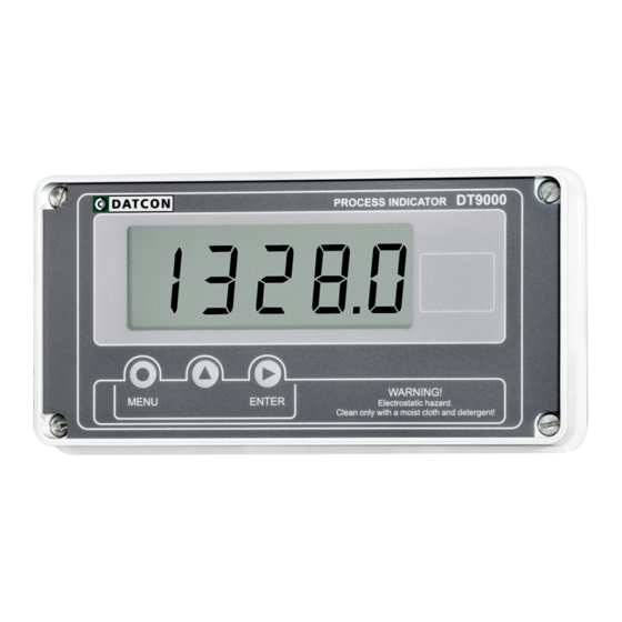
Page 21: Display And Manual Controls
DT9000 6. Display and manual controls 6.1. The first start-up The display The display is indicated by the arrow (1) After the instrument has been installed and connected into the current loop, first you see on the display the type of ... -
Page 22: Characters And Mnemonics Appearing On The Display
DT9000 6.2. Characters and mnemonics appearing on the display DT9000 has a 7-segment type display. It means that maximum 7 bars are used to form each characters. The numbers can be read easily, some of the letters, marks however, looks unusual: ... - Page 23 DT9000 Messages of critical errors A/D failure (Service: AD Hardware) EEPROM failure (Service: EEPROM Hardware) EEPROM write error (Service: EEPROM Protected) Calibration error (Service: Calibration) Default factory settings (Service: Default Factory Settings) The last saving was not successful (Error: Last Save) ...
- Page 24 DT9000 During setting up The instrument is making calculations, please wait (Busy) The requested operation has been completed (Ready) The saving of the settings is being done (Save) No, I don’t want this menu (No) Yes, the menu can be started (Yes) ...
-
Page 25: Manual Controls
DT9000 6.3. Manual controls DT9000 can be adjusted by the membrane push-buttons indicated by (1), (2), and (3) in the drawing. Functions of the push-buttons during measurement (1) MENU button: Entering the menu When you push this button, the device will ask for a password (code) in accordance with Chapter 7.1. - Page 26 DT9000 Using this function: 1. Press the ▲ button as long as you see this: This mnemonic indicates that it will be displayed the minimum value measured after the last clear. 2. Keeping the button pressed down, after 1.5 sec the minimum value will be displayed as long as the button is pressed down.
- Page 27 DT9000 (3) ENTER button: displaying the status of the limit output and clearing the alarm (alarm acknwledgement). It’s functionality depends on the operating mode of displaying the limits. In default factory setting this function is switched off, therefore pushing the button does not cause any changes.
-
Page 28: Setting-Up
DT9000 7. Setting-up 7.1. Typing the code (password) in The importance of the You may enter the menu only after you have typed your code code in. The code is made from 3 numeric characters. This solution prevents unauthorised persons from changing the settings of the instrument. - Page 29 DT9000 Automatic exit from If no buttons are pressed, the instrument displays the the request for the code mnemonic (Auto Escape) after 1 minute has passed from the last pressing of a button, and it RESTARTS, i. e. goes back to the measuring mode.
-
Page 30: The Menu
DT9000 7.2. The menu The menu structure 01: Limit-value display 31. page 02: Limit value 1 03: Limit value 1 33. page 04: Decimal point 41. page 05: Scale 4 mA 42. page 06: Scale 20 mA 44. page 07: Averaging number 46. -
Page 31: Display Modes Of Limit Output Status (01. Menu Item)
DT9000 7.3. Display modes of limit output status (01. menu item) Function The state of the limit outputs (whether they are switched on or off) can be displayed. Here you can define the conditions, on which displaying should depend. [Default factory setting: OFF] Sequence of operations 1. - Page 32 DT9000 Sequence of operations • : Always on (ON) It always displays the states of limit outputs. If you keep the ENTER button pressed down, the measurement results are displayed. (This operating mode is useful when the states of limit outputs is more important than the measured value.)
-
Page 33: Setting Up The Limit Outputs (02. And 03. Menu Items)
DT9000 7.4. Setting up the limit outputs (02. and 03. menu items) Function The instrument has two limit outputs. They are identical with each other, and work independently. Operation: the instrument keeps comparing the displayed physical value with the (adjustable) limit value. It switches the output ON depending whether the displayed value is higher than the limit value. - Page 34 DT9000 Setting the operating 5. Keep stepping by pressing the ▲ button you can select mode the desired limit-output operating mode. Sequence of operations • : the output is always in switched off condition. [default factory setting] ...
- Page 35 DT9000 Low limit value 8. Keep stepping by pressing the ▲ button as long as you Sequence of operations see this sub-menu item: . LL (Low Limit) means: the low limit value. Here you can define the numerical value by which the device will compare the measured physical values.
- Page 36 DT9000 Hysteresis of the low 16. Keep stepping by pressing the ▲ button as long as you limit see this sub-menu item: . LH (Low Hysteresis) Sequence of operations means: the hysteresis of the low limit value. Here you can...
- Page 37 DT9000 High limit value Setting the high limit value and It’s hysteresis is necessary Sequence of operations in that case only, if you had selected the or the operating mode. 23. Pressing the ▲ button keep stepping as long as you ...
- Page 38 DT9000 Hysteresis of the high 33. Keep stepping by pressing the ▲ button as long as you limit see this sub-menu item: . HH (High Hysteresis) Sequence of operations means: the hysteresis of the high limit value. Here you can...
-
Page 39: Limit Output Alarm Mode
DT9000 7.5. Limit output alarm mode Function In alarm mode, the limit output is switching on when the limit condition exist. But the output stays switched on (independent from the limit condition) until the ENTER button is pressed (alarm acknowledge). (All these information are described in detail in Chapter 7.4. - Page 40 DT9000 Exit from the menu item 1. After finishing the settings, press the MENU button to exit from the menu item, and you see this: 2. Press the MENU button to exit from the menu item, and you see this: (3.
-
Page 41: Decimal Point Position (04. Menu Item)
DT9000 7.6. Decimal point position (04. menu item) Function Setting the position of the decimal point on the display, or switching the decimal point off. [Default factory setting: 3 decimals] Sequence of operations 1. Enter the menu by typing the supervisor code. -
Page 42: The Physical Value Assigned To 4 Ma (05. Menu Item)
DT9000 7.7. The physical value assigned to 4 mA (05. menu item) Function Defining the physical value that should be assigned to the loop current value 4 mA, this can be any numerical value within the range that can be displayed (-20000 - 20000). - Page 43 DT9000 Exit from the menu item 1. After finishing the setting, press the MENU button, to exit from the menu item, and you see this: (2. If you want to change the setting you have done just now, or if you just want to check what you have typed in, go on with the operation from point 3 of the Sequence of operations.)
-
Page 44: The Physical Value Assigned To 20 Ma (06. Menu Item)
DT9000 7.8. The physical value assigned to 20 mA (06. menu item) Function Defining the physical value that should be assigned to the loop current value 20 mA, which can be any numerical value within the range that can be displayed (-20000 - 20000). - Page 45 DT9000 Sequence of operations 6. Pressing the ► button you can select the next digit. 7. Pressing the ▲ button you can increase the value of the blinking digit: , etc.
-
Page 46: The Number Of Averaged Measurements (07. Menu Item)
DT9000 7.9. The number of averaged measurements (07. menu item) Function The instrument performs cca. 15 measurements in each seconds. The displayed measurement result is generated as the average of several measurements. Here you can define the number of measurements that should be used for calculating the averaged numerical value. - Page 47 DT9000 Sequence of operations • : The displayed value is the same as the last measurement result; the previous measurements do not influence this value. (The display settling time after the stabilisation of the input signal: 0.1 second.) ...
-
Page 48: Display Refresh Time (08. Menu Item)
DT9000 7.10. Display refresh time (08. menu item) Function The instrument performs cca. 15 measurements in each seconds. It’s too fast to see the changing of the measurement value. Here you can define the time periods by which the instrument displays the new measurement values. - Page 49 DT9000 Exit from the menu item 1. After finishing the setting, press the MENU button, to exit the menu item, and you see this: (2. If you want to change the setting you have done just now, or if you just want to check what you have typed in, go on with the operation from point 3 of the Sequence of operations.)
-
Page 50: Tests (09. Menu Item)
DT9000 7.11. Tests (09. menu item) Function Checking the display and the limit outputs. Sequence of operations 1. Enter the menu by typing either the user code or the supervisor code. The way the code should be type in is described in Chapter ... - Page 51 DT9000 Sequence of operations Comment: the status you have selected here remains unchanged as long as you exit the menu, and the instrument starts measuring. 10. You can exit from the display test by pressing the MENU button. You see the blinking mnemonic.
-
Page 52: Changing The User Code (10. Menu Item)
DT9000 7.12. Changing the user code (10. menu item) Function You can define new codes instead of the factory-defined user code. The code is an optional number within the range between 000 and 999. [Default factory setting: 000] Sequence of operations 1. Enter the menu by typing either the user code or the supervisor code. - Page 53 DT9000 Sequence of operations 9. If the codes written in for the first and second time are identical with each other, the device exits from the menu item. You see this on the display. Do not forget the user code you have specified. If you forget it, defining another one is possible only by using a supervisor code for entering into the menu.
-
Page 54: Changing The Supervisor Code (11. Menu Item)
DT9000 7.13. Changing the supervisor code (11. menu item) Function You can define new codes instead of the factory-defined supervisor code. The code is an optional number within the range between 000 and 999. [Default factory setting: 100] Sequence of operations 1. Enter the menu by typing the supervisor code. - Page 55 DT9000 Sequence of operations 9. If the codes type in for the first and second time are identical with each other, the instrument exits from the menu item. You see this on the display. Do not forget the supervisor code you have specified. If you forget it, defining another one is possible in the service only.
-
Page 56: Display Operating Modes (12. Menu Item)
DT9000 7.14. Display operating modes (12. menu item) Function The instrument has a 4-and-a-half-digit display. It is possible to switch it into a 3-and-a-half-digit display mode. In this case the display behaves like a 3-and-a-half-digit display during measurement. (The mnemonics are displayed in four digits). - Page 57 DT9000 Exit from the menu item 1. After finishing the setting, press the MENU button, to exit from the menu item, and you see this: (2. If you want to change the setting you have performed just now, or if you just want to check what you have typed in, continue the operation from Point 3 of the Sequence of operations.)
-
Page 58: Disable Displaying The Leader Zeros (13. Menu Item)
DT9000 7.15. Disable displaying the leader zeros (13. menu item) Function Leader zero: the zeros that stand before an integer of no value. E.g. the instrument displays the value 5.2 together with the leader zeros: (default factory setting), or without the leader ... - Page 59 DT9000 Exit from the menu item 1. After you have performed the setting, press the MENU button. This takes you out from the menu item, and you see this: (2. If you want to change the setting you have done just...
-
Page 60: Clear Minimum And Maximum Values (14. Menu Item)
DT9000 7.16. Clear minimum and maximum values (14. menu item) Function To clear the measured and stored mimimum and maximum values. Sequence of operations 1. Enter the menu by typing the supervisor code. The way the code should be type in is described in Chapter 7.1. -
Page 61: Resetting The Default Settings (15. Menu Item)
DT9000 7.17. Resetting the default settings (15. menu item) Function In this case all the settings are deleted, and the default factory setting is restored. Using this function makes sense in that case, when the settings of the instrument have changed so much, that it is easier to start the setting-up process from the default factory setting. -
Page 62: Fault Rectification
DATCON personnel. In the case of errors, it is recommended to notice of the displayed error message, as well as of the phenomenon seen. These information please communicate to the Datcon service personnel. 9. Dismounting 9.1. Dismounting procedure The steps described in Chapter 4. -
Page 63: Appendix
DT9000 10. Appendix 10.1. Technical specifications Intrinsical safety data Certification: BKI 15 ATEX 0027 X, BKI 15 ATEX 0027 X/1 Marking: II 1G Ex ia IIC T6 Ga (-20 ºC < Ta < 60 ºC) Ex safety data Input safety data: 0... - Page 64 DT9000 Accuracy: 4 mA: typical 1 μA max. 3 μA (23 ˚C ±2 ˚C) 4 mA: typical 2 μA max. 7 μA (-20 - +60 ˚C) 20 mA: typical 2 μA max. 5 μA (23 ˚C ±2 ˚C) 20 mA: typical 8 μA max.
-
Page 65: Application Example
DT9000 10.2. Application example 20171205-V2... -
Page 66: Error Messages
DT9000 10.3. Error messages The instrument has a sophisticated self-testing function; it is capable of detecting the majority of the errors. All mnemonics (code words) presented on the display comes from English expressions in abbreviated form. A/D overflow (Error: A/D Overflow) ... -
Page 67: Messages Of Critical Errors
10.4. Messages of critical errors Such errors are caused normally by structural injuries or damages. Repair is done by the service of Datcon. In case of error it is recommended to notice of the displayed error message, as well as of the phenomenon seen and communicate to the Datcon service personnel. -
Page 68: Description Of The Menu Items
DT9000 10.5. Description of the menu items You find a description of the menu items in the following part. A description on the handling of the menu is in Chapter 7. Settings. Display modes of limit output status (Limit Displaying) ... - Page 69 DT9000 Physical value assigned to 4 mA The physical value to be assigned to the 4 mA loop current. Access is possible Any values can be defined for it within the minimum- by supervisor code only maximum interval that can be displayed . [Default factory...
- Page 70 DT9000 Changing the User Code (User Code) The new User Code must be typed in twice, in order to avoid any typing errors. The mnemonic (Re-Type) warns you to type the code for the second time, after you have typed it once.
-
Page 71: Messages And Error Messages During Setting Up
DT9000 10.6. Messages and error messages during setting up The following mnemonics may displayed when the settings are being performed. The value you have defined is lower than permissible (Low Limit) The instrument has replaced the value you have defined to the permitted lowest value. -
Page 72: Setting Up The Instrument (Example)
10.7. Setting up the instrument (Example) Exercise There is a pressure transmitter with a measurement range of 5-150 bar corresponds to 4-20 mA. Let the settings of DT9000 be the following: • Number of decimals: 2. • The physical value assigned for the 4 mA current: 5.00 •... - Page 73 DT9000 Setting the physical 1. Pressing the ▲ button keep stepping as long as you see value assigned to 20 mA this menu item: 2. Enter the menu item by pressing the ENTER button. 3. Pressing the ▲ button you can increase the value of the blinking number: 4.
-
Page 74: The Limit Outputs (Training Material)
DT9000 10.8. The limit outputs (training material) Outputs The DT9000 has two optically isolated limit outputs that work independently from each other. The two outputs are equivalent. The following information and examples relate to output No.1. All these, however, are applicable for output No.2 too, without modification. - Page 75 DT9000 Limit output sub-menu In the menu, the second menu-item ( ) contains all the parameters that relate to the limit output No.1. When you enter the menu, you get into a sub-menu. The menu structure is presented by the figure 7.2. Menu structure.
- Page 76 DT9000 Detailed description of The operating modes define the conditions under which the the operating mode limit output should switch ON depending on the value of the measured and displayed physical signal. Switched OFF The output is always switched OFF. [default factory setting] ≥...
- Page 77 DT9000 Example: Comment: the precondition for the following examples is Hysteresis > 0 that the output is in mode, that is, it switches ON when the measured value ≥ L1.LL (low limit). The input signal has an increasing characteristic, but rippled.
- Page 78 DT9000 Example: If you want the output to switch ON only once in the case Hysteresis > 0 of the signal presented by the previous example, then set the value of the hysteresis higher than 0. In practice the hysteresis value could be depend from two aspects: •...
- Page 79 DT9000 Detailed description of the limit value operating modes • : Switched OFF [this is the default factory setting] Independent of the measured value, the limit output is always switched OFF. • : It switches ON, when: measured value ≥ low limit The output switches ON, if the displayed value ≥...
- Page 80 DT9000 • : It switches ON, when the measured value < low limit The output switches ON, if the displayed value is lower . than the numerical value defined as the parameter. . In this operating mode the value of the...
- Page 81 DT9000 • : It switches ON, when (measured value ≥ low limit) AND (measured value ≤ high limit) The output switches ON, when the displayed value ≥ . numerical value defined as the parameter AND, . besides, it is ≤ numerical value defined as the...
- Page 82 DT9000 • : It switches ON, when (measured value < low limit) OR (measured value > high limit) The output switches ON, when the displayed value is lower than the numerical value defined as the parameter ...
- Page 83 DT9000 Alarm Mode The limit output may work in Alarm mode too. This mode is switched ON by the parameter. According to the default factory setting it is switched off ( ). When the Alarm mode is ON (...
- Page 84 DT9000 Example for the practical usage of the limit outputs There is a 100-litre tank, whose liquid level is indicated by the instrument DT9000 in 0-100 litres, without decimals. Task: The limit output No.1 should control a pump, that switches ON when the liquid-level goes lower than 70 litres, and switches OFF when it goes higher than 90 litres.
-
Page 85: Atex Certification
DT9000 10.9. ATEX Certification 20171205-V2... - Page 86 DT9000 20171205-V2...
- Page 87 DT9000 20171205-V2...
- Page 88 DT9000 20171205-V2...
- Page 89 DT9000 20171205-V2...
- Page 90 DT9000 20171205-V2...
- Page 91 DT9000 20171205-V2...
- Page 92 DT9000 20171205-V2...
- Page 93 DT9000 20171205-V2...
- Page 94 DT9000 20171205-V2...
- Page 95 DT9000 20171205-V2...
Need help?
Do you have a question about the DT9000 and is the answer not in the manual?
Questions and answers