Table of Contents
Advertisement
Quick Links
Advertisement
Table of Contents

Related Manuals for Datcon DT4260 Series


Summary of Contents for Datcon DT4260 Series
- Page 1 DT4260 xx xx xx xx AC Current Meter Operating Instructions...
-
Page 2: Table Of Contents
DT4260 xx xx xx xx Contents 1. About this document.............4 1.1. Function..................4 1.2. Target group................4 1.3. Symbolism used................4 2. For your safety..............5 2.1. Authorized personnel..............5 2.2. Appropriate use.................5 2.3. Warning about misuse...............5 2.4. General safety instructions............5 2.5. CE conformity................5 2.6. Environmental instructions............5 3. - Page 3 DT4260 xx xx xx xx 6. Display and manual controls........21 6.1. The first start-up...............21 6.2. Characters and mnemonics appearing on the display....22 6.3. Manual controls, display, indicators........25 Setting-up..............28 7.1. Typing the code (password) in..........28 7.2. The menu structure..............30 7.3. Display brightness (01. menu item).........31 7.4.
-
Page 4: About This Document
DT4260 xx xx xx xx 1. About this document 1.1. Function This operating instructions manual has all the information you need for quick set-up and safe operation of DT4260 xx xx xx xx. Please read this manual before you start setup. 1.2. -
Page 5: For Your Safety
For safety and warranty reasons, any internal work on the instruments must be carried out only by DATCON personnel. 2.2. Appropriate use A DT4260 xx xx xx xx AC Current Meter measure AC current in 0-1 A or 0-5 A ranges. -
Page 6: Product Description
DT4260 xx xx xx xx 3. Product description 3.1. Delivery configuration Delivered items The scope of delivery encompasses: • DT4260 xx xx xx xx • 1 pc panel sealing (1) • 2 pc mounting clamps (enclosed in a nylon bag) •... -
Page 7: Principle Of Operation
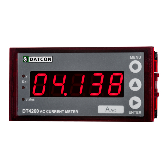
DT4260 xx xx xx xx 3.3. Principle of operation Area of application The DT4260 xx xx xx xx AC Current Meter enable 0-1 AAC / 0-5 AAC current ranges to be displayed on the control panel. Large 14.2 mm height LED display make process value easily visible at a distance. -
Page 8: Adjustment
DT4260 xx xx xx xx Operating principle The measuring current flows through the input shunt resistor. The voltage drop on the shunt resistor is lead to the signal conditioner and TRMS / DC converter stage. The DC voltage output of this stage is converted by a 21 bit A/D converter into digital value. -
Page 9: Display, Indicators
DT4260 xx xx xx xx 3.5. Display, indicators The following figure shows the front panel of the instrument: 1. 5 digit LED display displaying the measured value and the mnemonic messages. 2. „Rel1” yellow indicator for indicating that limit output 1 is in “on-state”... -
Page 10: Mounting
DT4260 xx xx xx xx 4. Mounting 4.1. General instructions Use the enclosed seal between the instrument and the panel when mounting the instrument to assure IP 65 from the front. Mounting positions Select a mounting position you can easily read the display reach for mounting and connecting the instrument and that minimises the hazard of water, dust or dump getting into the instrument. -
Page 11: Mounting
DT4260 xx xx xx xx 4.3. Mounting Preparatory steps The instrument is housed in a DIN standard 96 x 48 mm ABS case. It can be fix in the panel with the two enclosed mounting clamps. Dimensions of panel cutout 1. - Page 12 DT4260 xx xx xx xx Mounting with the mounting clamps 2. Put on the enclosed seal onto the instrument case from the rear side and fit it to the instrument holding frame (Figure step 2). 3. Put the instrument into the prepared cut-out until it possible and check the fitting of the seal between case and mounting surface.
-
Page 13: Connecting
DT4260 xx xx xx xx 5. Connecting 5.1. Preparing the connection Always observe the following safety instructions: • Connect or disconnect only in the complete absence of line voltage • You should take note the data concerning on the overcurrent protection in installation. •... -
Page 14: Connecting The Mains
DT4260 xx xx xx xx 5.2. Connecting the mains The following figure shows the wiring plan, connecting the DT4260 xx xx xx PS type instrument to the mains: Wiring plan, connecting the instrument to the mains (see also “Application example”) In case of DC supply the polarity is indifferent The following figure shows the wiring plan, connecting the... -
Page 15: Connecting The Input
DT4260 xx xx xx xx 5.3. Connecting the input The following figure shows the wiring plan, connecting the input to the current transformer: Wiring plan, connecting the input (see also “Application example”) 1. Loosen terminal screws. 2. Insert the wire ends into the open terminals according to the wiring plan. -
Page 16: Connecting The Limit Relay Outputs (Option)
DT4260 xx xx xx xx 5.4. Connecting the limit relay outputs (option). The following figure shows the wiring plan, connecting the limit relay outputs: Wiring plan, connecting the limit relay outputs (see also “Application example”) 1. Loosen terminal screws. 2. Insert the wire ends into the open terminals according to the wiring plan. -
Page 17: Connecting The Analogue Output (Option)
DT4260 xx xx xx xx 5.5. Connecting the analogue output (option). The following figure shows the wiring plan, connecting analogue output in case of active (DT4260 xx xx IA xx) or in case of passive (DT4260 xx xx IP xx) output: Wiring plan, connecting the analogue output (see also “Application... -
Page 18: Connecting The Rs232 Modbus Communication Output (Option)
DT4260 xx xx xx xx 5.6. Connecting the RS232 Modbus communication output (option). The following figure shows the wiring plan, connecting the RS232 Modbus communication output (DT4260 xx xx RS2 xx): Wiring plan, connecting the RS232 output (see also “Application example”) Be careful the polarity of the cables. -
Page 19: Connecting The Rs485 Modbus Communication Output (Option)
DT4260 xx xx xx xx 5.7. Connecting the RS485 Modbus communication output (option). The following figure shows the wiring plan, connecting the RS485 Modbus communication output (DT4260 xx xx RS4 xx): Wiring plan, connecting the RS485 output (see also “Application example”) Be careful the polarity of the cables. - Page 20 DT4260 xx xx xx xx Checking the Check if the cables are connected properly (have you connections connected all the cables, have you connected to the right place, do not the cable-ends touch each other). Put the instrument Put the instrument under supply voltage under supply voltage After you have completed the connections, put the instrument under supply voltage.
-
Page 21: Display And Manual Controls
DT4260 xx xx xx xx 6. Display and manual controls 6.1. The first start-up The display The display is indicated by the arrow (1) After the instrument has been installed and connected to the power supply, first you see on the display the value of the input current. -
Page 22: Characters And Mnemonics Appearing On The Display
Login text DT - Datcon instrument, 4260 - Type of the instrument 1 A - measuring range = 1 A, 5 A - measuring range = 5 A 20111006-V020111006... - Page 23 DT4260 xx xx xx xx Login text No output option is installed. (No Option = no option) - the text is blinking. RS-232 output option is installed. RS-485 output option is installed. Passive analogue option is installed. (Analog, Passive) ...
- Page 24 DT4260 xx xx xx xx During code writing Code? (Code) - type in the code! Bad code (Bad Code) A User login took place (User), A Supervisor login took place (Supervisor) During setting The typed number is lower than allowed (Low Limit) ...
-
Page 25: Manual Controls, Display, Indicators
DT4260 xx xx xx xx 6.3. Manual controls, display, indicators DT4260 xx xx xx xx can be adjusted by the membrane push-buttons indicated by (1), (2), and (3) in the drawing. Functions of the push-buttons during measurement (1) MENU button: Entering the menu When you push this button, the instrument will ask for a password (code) in accordance with Chapter 7.1. - Page 26 DT4260 xx xx xx xx 3. Press the ▲ button second time as long as you see this: The mnemonic indicates that it will be displayed the maximum value measured after the last clear. 4. Keeping the button pressed down, after 1.5 sec the maximum value will be displayed as long as the button is pressed down.
- Page 27 DT4260 xx xx xx xx indicators The following figure shows the 3 yellow indicator on the left side of DT4260 xx xx xx xx front panel: (1) Rel 1: limit output indicator (yellow) indicates that the limit output 1 is in “on-state” (LIMIT1). (2) Rel 2: limit output indicator (yellow) indicates that the limit output 1 is in “on-state”...
-
Page 28: Setting-Up
DT4260 xx xx xx xx 7. Setting-up 7.1. Typing the code (password) in The importance of the You may enter the menu only after you have typed your code code in. The code is made from 3 numeric characters. This solution prevents unauthorised persons from changing the settings of the instrument. - Page 29 DT4260 xx xx xx xx Automatic exit from If no buttons are pressed, the instrument displays the the request for the code mnemonic (Auto Escape) after 1 minute has passed from the last pressing of a button, and it RESTARTS, i.
-
Page 30: The Menu Structure
DT4260 xx xx xx xx The menu structure 7.2. 01: Display brightness 31. page 03: Current transform. ratio (IX) 32. page 06: Leading zeros enable/disab. 33. page 08: Averaging number 34. page 09: Display refresh time 36. page 10: #1 Limit output 11: #2 Limit output 37. -
Page 31: Display Brightness (01. Menu Item)
DT4260 xx xx xx xx 7.3. Display brightness (01. menu item) Function The brightness can be set between 10%-100%, in 10% steps. [factory default: 100%] Sequence of operations 1. Enter the menu by the user or the supervisor code. Chapter 7.1. Typing the code in describes how you can type the code in. -
Page 32: Current Transformer Ratio (Ix) (03. Menu Item)
DT4260 xx xx xx xx 7.4. Current transformer ratio (IX) (03. menu item) Function The instrument measures the current through a current transformer. Here you can set the current transformer ratio IX, so the display will show the current flows at the transformer primary coil. -
Page 33: Leading Zero(S) Enable / Disable (06. Menu Item)
DT4260 xx xx xx xx 7.5. Leading zero(s) enable / disable (06. menu item) Function Leading zero(s): valueless zero(s) prior number. E.g. the 0.123 A current value the instrument able to display in two different format: [factory default] or without leading zero: In this menu item can set this two display modes. -
Page 34: The Number Of Averaged Measurements (08. Menu Item)
DT4260 xx xx xx xx 7.6. The number of averaged measurements (08. menu item) Function The instrument performs cca. 12 measurements in each seconds. The displayed measurement result is generated as the average of several measurements. Here you can define the number of measurements that should be used for calculating the averaged numerical value. - Page 35 DT4260 xx xx xx xx Exit from the menu item 1. After finishing the setting, press the MENU button, to exit from the menu item, and you see this: (2. If you want to change the setting you have done just now, or if you just want to check what you have typed in, go on with the operation from point 3 of the Sequence of operations.)
-
Page 36: Display Refresh Time (09. Menu Item)
DT4260 xx xx xx xx 7.7. Display refresh time (09. menu item) Function The instrument performs cca. 12 measurements in each seconds. It’s too fast to see the changing of the measurement value. Here you can define the time periods by which the instrument displays the new measurement values. -
Page 37: Setting Limit Outputs (10., 11. Menu Item)
DT4260 xx xx xx xx 7.8. Setting limit outputs (10., 11. menu item) Function The instrument has two optional limit outputs. They are identical with each other, and work independently. Operation: the instrument keeps comparing the displayed physical value with the (adjustable) limit value. It switches the output ON or outpot OFF depending whether the displayed value is higher or lower than the limit value. - Page 38 H.LI, than the state of limit output doesn’t change. This operating mode is used in other DATCON instruments. Here you can use it at any control task where the AC current is the process value and you can control the process through the limit outputs.
- Page 39 DT4260 xx xx xx xx Low limit value 8. Keep stepping by pressing the ▲ button as long as you Sequence of operations see this sub-menu item: (Limit1 Low Limit = = limit 1, low limit value). Here you can define the numerical value by which the device will compare the measured physical values.
- Page 40 DT4260 xx xx xx xx View of the used terms The figure shows the limit output change vs. input signal, where the value of hysteresis is > 0. Remark: this operation is working in the mode: Setting the hysteresis 17.
- Page 41 DT4260 xx xx xx xx High limit value 23. Keep stepping by pressing the ▲ button as long as you Sequence of operation see this sub-menu item: (Limit1 High Limit = limit 1, high limit value). Here you can define a second numerical value with which the instrument will compare the displayed ...
- Page 42 DT4260 xx xx xx xx Limit output hold mode In case of basic operating mode the limit output is switching on or switching off when the conditions are exist. In limit output hold mode the output is kept in switched state and only by pressing ENTER button can be reset (limit signaling acknowledge).
-
Page 43: Limit Output State Display Mode (12. Menu Item)
DT4260 xx xx xx xx 7.9. Limit output state display mode (12. menu item) Function The state of limit outputs may present on the display. Here you can set the condition of presenting the states. [Factory default: dynamic] Sequence of operations 1. Enter the menu by typing the user or supervisor code. The way the code should be type in is described in Chapter ... - Page 44 DT4260 xx xx xx xx Sequence of operations • (On = switched on) It displays the limit output state continuously. Keeping the ENTER button pressed it displays the measuring value. • (Off = switched off) There is no limit output display. Remark: Independent from the limit output state display mode the front panel indicators always signal the limit output states.
-
Page 45: Clear Minimum And Maximum Values (13. Menu Item)
DT4260 xx xx xx xx 7.10. Clear minimum and maximum values (13. menu item) Function To clear the measured and stored mimimum and maximum values. Sequence of operations 1. Enter the menu by typing the supervisor code. The way the code should be type in is described in Chapter 7.1. -
Page 46: Analoge Output Signal Setting (14. Menu Item)
DT4260 xx xx xx xx 7.11. Analoge output signal setting (14. menu item) Function In this menu item you can choose between 4-20 mA and 0-20 mA output current. [Factory default: 4-20 mA] Sequence of operations 1. Enter the menu by typing a supervisor code. The way the code should be type is described in Chapter ... -
Page 47: Assignment Analog Output Low Value To Display Value (Scaling) (15. Menu Item)
DT4260 xx xx xx xx 7.12. Assignment analog output low value to display value (scaling) (15. menu item) Function Here you can assigne analog output low value (0 mA or 4 mA) to the display (AC current) value. This way you can assigne any phisical range to any output range. - Page 48 DT4260 xx xx xx xx Exit from the menu item 1. After finishing the setting, press the MENU button, to exit from the menu item, and you see this: (2. If you want to change the setting you have performed just now, or if you just want to check what you have typed in, continue the operation from Point 3 of the Sequence of operations.)
-
Page 49: Assignment Analog Output High Value To Display Value (Scaling) (16. Menu Item)
DT4260 xx xx xx xx 7.13. Assignment analog output high value to display value (scaling) (16. menu item) Function Here you can assigne analog output high value (20 mA) to the display (AC current) value. This way you can assigne any phisical range to any output range. - Page 50 DT4260 xx xx xx xx Exit from the menu item 1. After finishing the setting, press the MENU button, to exit from the menu item, and you see this: (2. If you want to change the setting you have performed just now, or if you just want to check what you have typed in, continue the operation from Point 3 of the Sequence of operations.)
-
Page 51: Modbus Communication Settings (17. Menu Item)
DT4260 xx xx xx xx 7.14. MODBUS communication settings (17. menu item) Function Communication output with MODBUS RTU slave protocol. The instrument can be connected to the PLC or to the computer. Here you can find how to set communication parameters. Note 1: When no communication option is installed than these parameters are indifferent. - Page 52 DT4260 xx xx xx xx MODBUS bit/sec setting 9. Keep stepping by pressing the ▲ button as long as you Sequence of operations see this menu item: (MODBUS Baud Rate = MODBUS bit / seconds rate). 10. Enter the menu item by pressing the ENTER button. ...
- Page 53 DT4260 xx xx xx xx MODBUS respons delay 18. Keep stepping by pressing the ▲ button as long as you time setting (ms) see this menu item: (MODBUS Wait = MODBUS Sequence of operations wait). 19. Enter the menu item by pressing the ENTER button. ...
-
Page 54: Tests (18. Menu Item)
DT4260 xx xx xx xx 7.15. Tests (18. menu item) Function Testing the display, the digital outputs and the analog output. Display test 1. Enter the menu by typing either the user code or the Sequence of operations supervisor code. The way the code should be type in is described in Chapter ... - Page 55 DT4260 xx xx xx xx Digital output test 8. Keep stepping by pressing ▲ button as long as you see Sequence of operations this menu item: (Test: Digital Output = digital output test). 9. Enter the menu item by pressing the ENTER button. ...
- Page 56 DT4260 xx xx xx xx Exit from menu item 1. Press the MENU button, to exit from the menu item, and you see this: (2. If you want to make further testing, continue the operation from Point 3 of the Sequence of operations.) (3.
-
Page 57: Changing The User Code (19. Menu Item)
DT4260 xx xx xx xx 7.16. Changing the user code (19. menu item) Function You can define new codes instead of the factory-defined user code. The code is an optional number within the range between 0000 and 9999. [Default factory setting: 0000] Sequence of operations 1. - Page 58 DT4260 xx xx xx xx Sequence of operations Do not forget the user code you have specified. If you forget it, defining another one is possible only by using a supervisor code for entering into the menu. Exit from the menu item 1. As you have already left the menu item there is no need further settings.
-
Page 59: Changing The Supervisor Code (20. Menu Item)
DT4260 xx xx xx xx 7.17. Changing the supervisor code (20. menu item) Function You can define new codes instead of the factory-defined supervisor code. The code is an optional number within the range between 0000-9999. [Default factory setting: 1000] Sequence of operations 1. - Page 60 DT4260 xx xx xx xx Sequence of operations Do not forget the supervisor code you have specified. If you forget it, defining another one is possible in the service only. Exit from the menu item 1. As you have already left the menu item there is no need further settings.
-
Page 61: Resetting The Default Settings (21. Menu Item)
DT4260 xx xx xx xx 7.18. Resetting the default settings (21. menu item) Function In this case all the settings are deleted, and the default factory setting is restored. Using this function makes sense in that case, when the settings of the instrument have changed so much, that it is easier to start the setting-up process from the default factory setting. -
Page 62: Fault Rectification
DATCON personnel. In the case of errors, it is recommended to notice of the displayed error message, as well as of the phenomenon seen. These information please communicate to the Datcon service personnel. 20111006-V020111006... -
Page 63: Dismounting
DT4260 xx xx xx xx 9. Dismounting 9.1. Dismounting procedure Before dismounting take note the warnings written in Chapter 5.1. The following figure shows the dismounting procedures: Dismounting The dismounting procedure needs a screwdriver for slotted screws. Before dismounting disconnect all wires. 1. -
Page 64: Appendix
DT4260 xx xx xx xx 10. Appendix 10.1. Technical specifications Safety data: The connection terminals of the inputs, the outputs and the supply voltages are galvanic isolated from each other. The isolation is in compliance with the standard EN 61010-1, taking into consideration the following: Pollution level: Measurement category: Overcurrent protection in installation:... - Page 65 DT4260 xx xx xx xx Measuring parameters Characteristic: linear Display accuracy: 0.2% @ Ta = 23˚C ±2˚C, (after 20 min warm up time) Temperature-dependency: 25 ppm / ˚C Measuring frequency: 12 measurements / sec Number of averaged samples: 1 / 2 / 4 / 8 / 16 / 32 / 64 (adjustable) Limit outputs (optional) Output type: 2 x SPDT relays...
- Page 66 DT4260 xx xx xx xx Communication interface (optional) Type: RS232 or RS485, (isolated) Isolation voltage: 0.5 kV RS485 termination resistance: 135 ohm, you can switch on by using a short on the terminals Baud rate: 300 / 600 / 1200 / 2400 / 4800 / 9600 Baud Parity: even / odd / none Protocol:...
- Page 67 DT4260 xx xx xx xx General data Housing: panel instrument Dimensions [mm]: 96 x 48 x 45 (width x height x depth) Panel cut off: 91 x 44 (width x height) Weight: 0.15 kg Protection: IP 65 (front) IP 30 (rear) Mounting position: optional Connection cable:...
-
Page 68: Application Example
DT4260 xx xx xx xx 10.2. Application example Analog output option: 20111006-V020111006... - Page 69 DT4260 xx xx xx xx RS232 communication interface option: 20111006-V0...
- Page 70 DT4260 xx xx xx xx RS484 communication interface option: 20111006-V020111006...
- Page 71 DT4260 xx xx xx xx RS485 bus topology: 20111006-V0...
-
Page 72: Setting Up The Instrument (Example)
DT4260 xx xx xx xx 10.3. Setting up the instrument (example) Remarks It is an additional example for Chapter 7. Setting-up. It helps to understand the setting of values through a practical example. The steps of the whole setting you will find in Chapter 7.. -
Page 73: Modbus Settings
DT4260 xx xx xx xx 10.4. MODBUS settings Codes before register addresses: R = Read only W = Write only RW = Read and Write Register addresses are in decimal numerical system. R1000: Displayed AC current value high 16 bit R1001: Displayed AC current value low 16 bit Remark: the displayed value is 32 bit, signed, integer.
Need help?
Do you have a question about the DT4260 Series and is the answer not in the manual?
Questions and answers