Sign In
Upload
Manuals
Brands
Datcon Manuals
Measuring Instruments
PQRM5300 33 U I Series
Datcon PQRM5300 33 U I Series Manuals
Manuals and User Guides for Datcon PQRM5300 33 U I Series. We have
1
Datcon PQRM5300 33 U I Series manual available for free PDF download: Instruction Manual
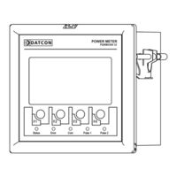
Datcon PQRM5300 33 U I Series Instruction Manual (92 pages)
Three-phase Power Meter
Brand:
Datcon
| Category:
Measuring Instruments
| Size: 5.52 MB
Table of Contents
Power Network with Neutral Conductor
1
Table of Contents
2
Phase Measurement with Neutral Conductor
3
About this Document
5
Function
5
Target Group
5
Symbolism Used
5
For Your Safety
6
Authorized Personnel
6
Appropriate Use
6
Warning about Misuse
6
General Safety Instructions
6
CE Conformity
6
Environmental Instructions
6
Product Description
7
Delivery Configuration
7
Type Designation
7
Operating Principle
8
Display, Indicators, Keyboard
10
Storage and Transport
11
Mounting
12
General Instructions
12
Main Dimensions of the Instrument
12
Mounting
13
Connecting
15
Preparing the Connection
15
Connecting the Measuring Inputs to Power Network. Three
16
Measuring)
16
Connecting the Measuring Inputs to Power Network. Three Phase Measurement Without Neutral Conductor. (3 Phase, 3 Wire, 3 Measuring)
17
Connecting the Measuring Inputs Trough Transformer to Power Network. Three Phase Measurement with Neutral Conductor. (3 Phase, 4 Wire, 3 Measuring)
18
Connecting the Measuring Inputs to Medium Voltage Power
19
Phase, 3 Wire, 3 Measuring)
19
Measuring)
20
Connecting the Measuring Inputs to Symmetrical Three-Phase Power Network Without Neutral Conductor. (3 Phase, 3 Wire, 1 Measuring)
21
Aron Mode (3 Phase, 3 Wire, 2 Measuring)
22
Connecting the Measuring Inputs to Three-Phase Power Network Trough Three-Phase Voltage Transformers Without Common Connection Point (3 Phase, 3 Wire, 3 Measuring, 3Fmv)
23
Connecting the Digital Outputs
24
Connecting to MODBUS RS485 Network
26
Connecting to ETHERNET Network
27
Connecting the Analog Output to Signal Processing Unit
28
Connecting the Power Supply
29
Setting - up
30
First Steps
30
Main Menu, Measured Data
31
Main Menu, Energy Menu
33
Main Menu, Harmonics Menu
33
Main Menu, Errors Menu
33
Main Menu, Power Limit
34
Main Menu, User Settings Menu
35
Main Menu, Configurations Menu
35
Settings
36
General Information
36
Required Settings
37
Entering Numbers (Editing Numbers)
38
Enter to User Settings Menu
39
Language Selection
39
Setting the Brightness of Displaybacklight
40
Editing the User Displays
41
Configurations Menu
42
Measure Input Settings
43
Measure Configuration
43
Voltage Transformers (VT) and Current Transformers (CT) Ratio Settings
45
Phase Lag of CT Settings
46
Sampling Time Setting
47
Current Threshold
48
Setting the Optional Modules
49
Digital Inputs and Outputs Settings
49
Digital Output, Energy Pulse Output Settings
50
Digital Output, Energy Sign Output Settings
52
Digital Output, Limit Output Settings
53
Digital Output, Alarm Output Settings
56
Digital Output, Demand Control Function Setting
57
Digital Output, Digital Output Test
59
Analogue Output Settings
60
Analogue Output Testing
61
Communication Interface
63
MODBUS RS485 Interface Setting
63
MODBUS TCP Ethernet Interface Setting
64
MODBUS Registers Format
65
Error LED Settings
80
Clear Errors
81
Clear the Energyregisters
82
Change the Password
82
Fault Rectification
83
Fault Finding
83
Repairing
83
Dismounting
84
Dismounting Procedure
84
Disposal
85
Appendix
86
Technical Specification
86
MODBUS RS485 Bus Topology
90
Ethernet Network Topology
91
Advertisement
Advertisement
Related Products
Datcon PQRM5100 11 U I Series
Datcon DT1102 V
Datcon DT4120 PS Series
Datcon DT4120 Series
Datcon DT4200
Datcon DT4220 E Series
Datcon DT4227 UI
Datcon DT4240 Series
Datcon DT4260 Series
Datcon DT7000
Datcon Categories
Measuring Instruments
Transmitter
Clock
Industrial Equipment
Power Supply
More Datcon Manuals
Login
Sign In
OR
Sign in with Facebook
Sign in with Google
Upload manual
Upload from disk
Upload from URL