Table of Contents
Advertisement
Quick Links
Advertisement
Table of Contents

Related Manuals for Datcon DT1102 V


Summary of Contents for Datcon DT1102 V
- Page 1 DT1102 V (PS) Fully Configurable Galvanic Isolator Operating Instructions...
-
Page 2: Table Of Contents
DT1102 V Contents . About this document..............4 1.1. Function....................4 1.2. Target group..................4 1.3. Symbolism used .................. 4 2. For your safety................5 2.1. Authorized personnel................5 2.2. Appropriate use ................... 5 2.3. Warning about misuse ................. 5 2.4. General safety instructions ..............5 2.5. - Page 3 DT1102 V 6. The first start-up, indicators ..........19 6.1. The first start-up ................19 6.2. Indicator LED-s......... Hiba! A könyvjelző nem létezik. Setting-up................21 7.1. First steps..................21 7.2. Analogue input type setting ............... 23 7.3. Analogue input range setting ............. 24 7.4.
-
Page 4: About This Document
1.1. Function This operating instructions manual has all the information you need for quick set-up and safe operation of DT1102 V (PS). Please read this manual before you start setup. 1.2. Target group This operating instructions manual is directed to trained personnel. -
Page 5: For Your Safety
2.5. CE conformity The DT1102 V (PS) is in conformity with the provisions of the following standards: MSZ EN 61326-1 (EMC) MSZ EN 61010-1 (Safety) 2.6. -
Page 6: Product Description
DT1102 V 3. Product description 3.1. Delivery configuration Delivered items The scope of delivery encompasses: • DT1102 V (PS) • documentation: this operating instructions manual certification warranty 3.2. Type designation 20230127-V0... -
Page 7: Operating Principle
DT1102 V 3.3. Operating principle Area of application The DT1102 V (PS) Fully Configurable Galvanic Isolator provide signal transmission and conversion between DC current or DC voltage signal source and signal processing units. The instruments feature complete 3-way isolation: the input, the output and the power supply are isolated from each other. -
Page 8: Adjustment
Power Supply: 230 V AC/DC ±10% 3.4. Adjustment After connecting the DT1102 V is ready to work with the factory default parameters are written in chapter 6.1. The first start-up. For working with the default parameters there is no need any adjustment. -
Page 9: Indicators, Usb Connector
10.1. Technical specification, as described under the title: Ambient conditions. The packaging of DT1102 V consist of environment-friendly, recyclable cardboard is used to protect the instrument against the impacts of normal stresses occurring during transportation. The corrugated cardboard box is made from environment-friendly, recyclable paper. -
Page 10: Mounting
DT1102 V 4. Mounting 4.1. General instructions The instrument should be installed in a cabinet with sufficient IP protection, where the operating conditions are in accordance with chapter 10.1. Technical specification, as described under the title: Ambient conditions. Mounting position The instruments are designed in a housing for mounting on TS-35 rail. -
Page 11: Mounting Procedure
DT1102 V 4.3. Mounting procedure The following figure shows the mounting procedures (fixing on the rail): Mounting on the rail The mounting doesn’t need any tool. 1. Tilt the instrument according to the figure; put the instrument’s mounting hole onto the upper edge of the rail (figure step 1.). -
Page 12: Connecting
DT1102 V 5. Connecting 5.1. Preparing the connection Always observe the following safety instructions: • The connection must be carried out by trained and authorized personnel only! • Connect or disconnect only in the complete absence of supply voltage •... -
Page 13: Connecting The Dc Current Signal Source
DT1102 V 5.2. Connecting the DC current signal source The following figure shows the wiring plan, connecting the DC current signal source: Wiring plan, connecting the DC current signal source (see also “Application example”) Be careful the polarity of the cables 1. -
Page 14: Connecting A -2.5 - +2.5 Vdc Voltage Signal Source
DT1102 V 5.3. Connecting a -2.5 - +2.5 VDC voltage signal source The following figure shows the wiring plan, connecting the DC voltage signal source: Wiring plan, connecting the DC voltage signal source (see also “Application example”) Be careful the polarity of the cables 1. -
Page 15: Connecting A -125 - +125 Vdc Voltage Signal Source
DT1102 V 5.4. Connecting a -125 - +125 VDC voltage signal source The following figure shows the wiring plan, connecting the DC voltage signal source: Wiring plan, connecting the DC voltage signal source (see also “Application example”) Be careful the polarity of the cables 1. -
Page 16: Connecting The Signal Processing Unit And The Power Supply
DT1102 V 5.5. Connecting the signal processing unit and the power supply The following figure shows the wiring plan, connecting the signal processing unit and the power supply: Wiring plan, connecting the signal processing unit and the power supply (see also “Application example”) - Page 17 DT1102 V 5.6. A tápellátás csatlakoztatása a készülékhez Az alábbi ábra mutatja a tápegység bekötését: Bekötési rajz, tápegység csatlakoztatás (lásd még “Alkalmazási példa”) DC tápellátás esetén a polaritás tetszőleges. 1. Lazítsa meg a sorkapocs csavarjait. 2. Helyezze az előkészített kábelvégeket a nyitott sorkapcsokba a bekötési rajz szerint.
-
Page 18: Connecting To Pc Via Usb Cable
DT1102 V 5.7. Connecting to PC via USB cable The following figure shows the USB connector on front of the instruments. 1. For the communication between PC and instruments plug the accessory USB cable (USB-B mini, 5 pins) to USB connector (1). -
Page 19: The First Start-Up, Indicators
DT1102 V 6. The first start-up, indicators 6.1. The first start-up After connecting the DT1102 V is ready to work with the factory default parameters. When you are going to use other parameters you should set-up the instrument according to chapter 7. Setting-up. -
Page 20: Indicator Led-S
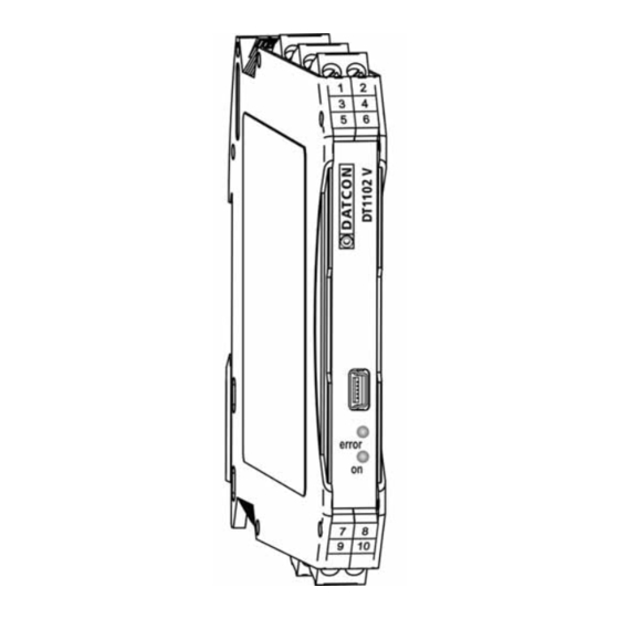
DT1102 V 6.2. Indicator LED-s The following figure shows the indicators and USB connector on the DT1102 V front panel. (2) The blinking light of „error” red indicator indicates different error states. (3) The continuous light of „on” green indicator indicates that the instrument is working. -
Page 21: Setting-Up
- Connect the instrument with the USB cable to the PC USB port. - If the windows runs the device installer application then browse and select the file “DT1102 V\USB Driver\MCP2200_v1.2.inf” and install it. Another method (if the first method failed): run the application"DT1102 V\USB Driver\Driver Installation... - Page 22 DT1102 V The virtual serial port setting panel (for USB communication): The all perspective of configuration program: 20230127-V0...
-
Page 23: Analogue Input Type Setting
DT1102 V 7.2. Analogue input type setting Function The instrument has two different inputs. The selectable input signal can be current or voltage. [Factory default: Current input] Sequence of operations 1. Select the appropriate input mode by clicking the button. -
Page 24: Analogue Input Range Setting
DT1102 V 7.3. Analogue input range setting Selectable input ranges: Function -25 - +25 mA @ current input Terminals: Common (7) and Iin (8). -2.5 - +2.5 V @ voltage 1 input Terminals: Common (7) and Uin1 (9). -125 - +125 V @ voltage 2 input Terminals Common (7) and Uin2 (10). -
Page 25: Analogue Output Type Setting
DT1102 V 7.4. Analogue output type setting Function The instrument has two output connectors: current output and voltage output. The selected output must be current or voltage, can not use both. The unused connector must be unconnected. [Factory default: Current output] Sequence of operations 1. -
Page 26: Analogue Output Range Setting
DT1102 V 7.5. Analogue output range setting Function Selectable output ranges: 0-22 mA @ current output Terminals: -Iout (5) and +Iout (6). 0-10.5 V @ voltage output Terminals: -Uout (3) and +Uout (4). The initial value and the end value can be set arbitrary within this range. -
Page 27: Resetting Default Setting
DT1102 V 7.6. Resetting default setting Function In this case all the settings are deleted, and the default settings are restored. Using this function makes sense in that case, when the settings of the instrument have changed so much, that it is easier to start the setting- up process from the default factory setting. -
Page 28: Display Measured Data
DT1102 V 7.7. Display measured data The program can read out and display the measured input and output values when the serial port is open. Function 7.8. Display system information The program can read out and display the system information when the serial port is open. -
Page 29: Display Errors
DT1102 V 7.9. Display errors The program can read out and display the error messages when the serial port is open. When the error occurs, the error message and the error code are visible. The figure shows how visible the “Output range error” status. -
Page 30: Fault Rectification
There is no output signal check the device connected to the input. When the result of fault finding is that the DT1102 V is defective call the manufacturer service department. 8.2. Repairing There is no user repairable part inside the instrument. -
Page 31: Dismounting
DT1102 V 9. Dismounting 9.1. Dismounting procedure Before dismounting take note the warnings written in chapter 5.1. Preparing the connection. The following figure shows the dismounting procedures. Dismounting from the rail The dismounting procedure needs a screwdriver for slotted screws. -
Page 32: Appendix
DT1102 V 10. Appendix 10.1. Technical specification Input parameters Input signal: DC current / DC voltage Maximum of input ranges: -125 - +125 V @Uin2 -2.5 - +2.5 V @ Uin1 -25 - +25 mA @ Iin Overload: 150 V... - Page 33 500 VDC (between output-power supply terminals) Power supply Power supply: DT1102 V 24 VDC ±10%, 1,2 W DT1102 V PS 230 V AC/DC ±10%, 1,9 VA (1,3 W) Overvoltage category: CAT II. Overcurrent protection: 4 A (B) Ambient conditions Operating temperature range: 0-60 °C...
- Page 34 DT1102 V General data Housing: TS-35 rail mounting housing material: polyamide PA6.6 Fireproof class: V2-V0 / UL94 Connection: Pluggable screw-terminal Connecting cable: 1.5 mm (max.) Dimensions: 12.5 x 108 x 114 mm (width x height x depth) Mass: 0.15 kg...
-
Page 35: Application Example
DT1102 V 10.2. Application example 20230127-V0...
Need help?
Do you have a question about the DT1102 V and is the answer not in the manual?
Questions and answers