Table of Contents
Advertisement
Quick Links
Advertisement
Table of Contents

Subscribe to Our Youtube Channel
Related Manuals for Norton clipper CM 352


Summary of Contents for Norton clipper CM 352
- Page 1 CM 352 OPERATING INSTRUCTIONS Translation of the original instructions...
- Page 2 VERS. 04.04.2019 MAN CM 352 EN...
- Page 3 VERS. 04.04.2019 MAN CM 352 EN Declaration of conformity The undersigned manufacturer: SAINT - GOBAIN ABRASIVES S.A. 190, BD J.F. KENNEDY L- 4930 BASCHARAGE Declares that this product: CM 352 115V UK 70184607385 Masonry Saws: Code: CM 352 230V 70184607386 is in conformity with the following Directives: ...
- Page 4 VERS. 04.04.2019 MAN CM 352 EN...
-
Page 5: Table Of Contents
VERS. 04.04.2019 MAN CM 352 EN CM 352 OPERATING INSTRUCTIONS TABLE OF CONTENTS 1 BASIC SAFETY INSTRUCTIONS 1.1 Symbols 1.2 Machine plate 1.3 Safety instructions for particular operating phases 2 MACHINES DESCRIPTION 2.1 Short description 2.2 Purpose of use 2.3 Layout 2.4 Technical data 2.5 Statement regarding the vibration emission 2.6 Statement regarding noise emission... -
Page 6: Basic Safety Instructions
MAN CM 352 EN 1 BASIC SAFETY INSTRUCTIONS The CM 41 is exclusively designed for the cutting of construction products, with NORTON diamond blades, mainly on construction sites. Uses other than the manufacturer's instructions shall be considered as contravening the regulations. The manufacturer shall not be held responsible for any resulting damage. -
Page 7: Machine Plate
Immediately remove damaged or badly worn blades, as they endanger the operator whilst rotating. Only fit NORTON diamond blades to the machine! The use of other tools can damage the machine! Please wear safety goggles and a dust mask when cutting dry to minimize the effects of dust. -
Page 8: Machines Description
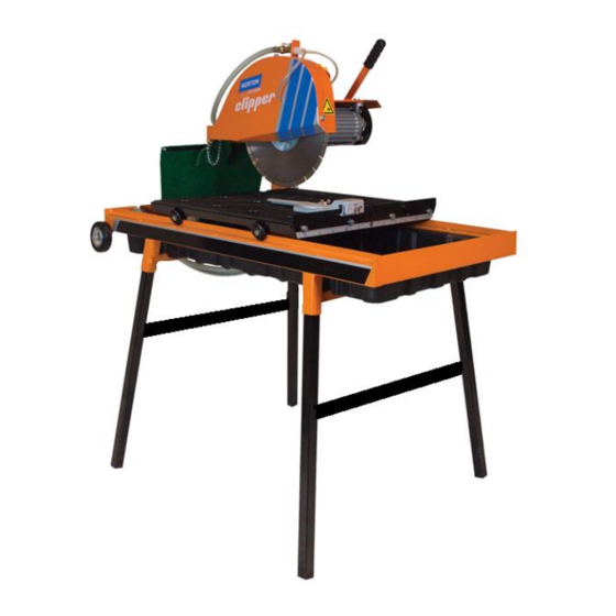
It can be used on construction or industrial site. Combined with NORTON diamond blades, it offers high performance and quality cuts of materials used in construction. The machine and its component parts are assembled to high standards assuring long life and minimum maintenance. - Page 9 VERS. 04.04.2019 MAN CM 352 EN Frame and feet (1) The frame is made of a jig-welded reinforced steel construction to ensure perfect rigidity. The machine is mounted on four removable legs 4 locked with screws and equipped of wheels for transportation. Cutting head (2) The pivot is jig-machined with precision.
-
Page 10: Technical Data
VERS. 04.04.2019 MAN CM 352 EN 2.4 Technical data Machines CM 352 2.2KW - 230V CM 352 1.8KW - 115V 2.2 kW 230V 1.8 kW 115V Motor With thermal overload With thermal overload protection protection Electric motor protection IP54 Max. blade diameter 350 mm Bore 25,4 mm... -
Page 11: Statement Regarding The Vibration Emission
VERS. 04.04.2019 MAN CM 352 EN 2.5 Statement regarding the vibration emission Declared value of vibration emission following EN 12096. Machine Measured value of vibration Uncertainty K Tool used Model / code emission at m/s Model / code CM 352 115V UK 70184607385 Clipper ALFA... -
Page 12: Statement Regarding Noise Emission
VERS. 04.04.2019 MAN CM 352 EN 2.6 Statement regarding noise emission Declared value of noise emission following EN ISO 11201 and NF EN ISO 3744. Machine Sound Uncertainty K Sound power Uncertainty K Model / code Pressure level (Sound level (Sound power level Pressure level EN ISO 11201... -
Page 13: Assembly And Commissioning
Mount the feet and tighten them with the locking screws. 3.2 Tool assembly Only NORTON blades with a maximum diameter of 350mm can be used. All tools used must be selected with regard to their maximum permitted cutting speed for the machine’s maximum permitted rotation speed. -
Page 14: Water Cooling System
VERS. 04.04.2019 MAN CM 352 EN 3.4 Water cooling system Fill the water tray with clean water (to approximately 3cm from top) to ensure that bottom of the pump is fully immersed in its decanting basket). The blade must be well cooled on both sides. You can adjust the water flow by the means of the water tap. -
Page 15: Transport And Storing
VERS. 04.04.2019 MAN CM 352 EN 4 TRANSPORT AND STORING 4.1 Securing for transport Before transporting the machine, please follow the following instructions: Always dismount the blade. Empty the water tray and remove it. Tighten the screws of the two water tray supports. ... -
Page 16: Operating The Machine
VERS. 04.04.2019 MAN CM 352 EN 5 OPERATING THE MACHINE Please find in this chapter advices to use the machine safely and correctly. 5.1 Installation 5.1.1 Information concerning the working site Remove from the site anything, which might hinder the working procedure. ... - Page 17 VERS. 04.04.2019 MAN CM 352 EN In full depth or fixed cutting, the cutting head is locked in a fixed position and the material is pushed into it as shown. Lower the cutting head to the desired cutting depth (in “through cutting”, lower cutting head until blade periphery reaches max.
- Page 18 VERS. 04.04.2019 MAN CM 352 EN 5.2.3 45° bevel cuts With the CM 352 it is possible to make fixed or multiple step bevel cuts. To tilt the cutting head to 45°, please follow the following instructions: Clear the conveyor cart in the front of the machine to give space to the pivot. ...
-
Page 19: Maintenance And Service
VERS. 04.04.2019 MAN CM 352 EN 6 MAINTENANCE AND SERVICE To ensure a long-term quality from the cutting and a safe functioning of the machine without any problem, please follow the maintenance plan below: Visual control general aspect, water Whole machine tightness Clean Flange and blade fixing devices... -
Page 20: Breakdown - Causes And Cures
VERS. 04.04.2019 MAN CM 352 EN 7 BREAKDOWN – CAUSES AND CURES 7.1 Breakdown-finding procedures Should any breakdown occur during the use of the machine, turn it off, and isolate it from the electrical supply. Any works dealing with the electrical system or supply of the machine can only be carried out by a qualified electrician. -
Page 21: Circuit Diagram 230V
VERS. 04.04.2019 MAN CM 352 EN 7.3 Circuit diagram 230V... -
Page 22: Customer Service
Spare parts for the motor can be ordered with the manufacturer of the motor or with their dealer, which is often quicker and cheaper! This machine has been manufactured by: Saint-Gobain Abrasives S.A.: 190, Bd. J. F. Kennedy L-4930 BASCHARAGE Grand-duché de Luxembourg Tel. : 00352 50 401 1 Fax. : 00331 83717792 http://www.construction.norton.eu Email : sales.nlx@saint-gobain.com... -
Page 23: Spare Parts
VERS. 04.04.2019 MAN CM 352 EN Spare parts In order to consult the spare parts lists, we invite you to visit the after-sales website of Norton Clipper by using the following address: https://spareparts.nortonabrasives.com For a quick access, you can also use the QR Code shown below using your mobile phone: This electronic catalogue provides exploded views and spare parts lists for different machines designed by Norton Clipper so you can find references you need. - Page 24 168 66 BROMMA • SVERIGE GERMANY SAINT-GOBAIN HPM POLSKA SP. Z O.O. SWEDEN TEL: +49 (0) 2236 703-1 UL. NORTON 1, TEL: +46 8 580 881 00 +49 (0) 2236 8996-0 62-600 KOŁO • POLAND FAX: +46 8 580 881 30...
Need help?
Do you have a question about the clipper CM 352 and is the answer not in the manual?
Questions and answers