
Subscribe to Our Youtube Channel
Related Manuals for Norton C1316


Summary of Contents for Norton C1316
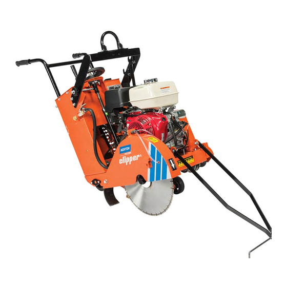
- Page 1 OWNERS MANUAL MEDIUM CONCRETE SAWS MODELS: C1316 C1316ES C2016 PC2016 C1320 C132ES C2020 PC2020 C2024 PC2024 FORM C2020 rev 9-07...
- Page 2 In no event shall Norton be liable for consequential or incidental damages arising out of the failure of any product to operate properly. Integral units such as gasoline engines, electric motors, batteries, tires, transmissions, etc., are excluded from this warranty and are...
-
Page 3: Table Of Contents
Table of Contents CONTENTS PAGE I. Preparation A. Safety Precautions B. Assembly C. Concrete Saw Specifications II. Operation A. Blade Installation 9-11 B. Changing the Blade Side 12-14- C. Starting The Engine D. Water Supply 14-15 E. Controls 15-17 F. Operating The Saw 17-19 G. -
Page 4: Preparation
I. PREPARATION A. Safety Precautions Important! The following safety precautions must always be observed. Hazard Symbols Fuel (gasoline) is extremely flammable and its vapors can explode if ignited. Store gasoline only in approved containers, in well ventilated, unoccupied areas approved, and away from sparks or flames. -
Page 5: Dust And Silica Warning
Dust and Silica Warning Grinding/cutting/drilling of masonry, concrete, metal and other materials can generate dust, mists and fumes containing chemicals known to cause serious or fatal injury or illness, such as respiratory disease, cancer, birth defects or other reproductive harm. If you are unfamiliar with the risks associated with the particular process and/or material being cut or the composition of the tool being used, review the material safety data sheet and/or consult your employer, the material manufacturer/supplier, governmental agencies such as OSHA and... - Page 6 1. Before mounting any blade on the saw, the blade should be inspected for any damage which might have occurred during shipment, handling or previous use. The blade collars and arbors should be cleaned and examined for damage before mounting the blade. 3.
-
Page 7: Assembly
Inspect the saw for shipping damage. If any damage is found, contact the shipper immediately and file a freight claim. The Norton Company is not responsible for any freight-related damages. Remove the saw from the pallet. Reverse the position of the handlebars so that the handle bar sticks out towards the operator. -
Page 8: Concrete Saw Specifications
C. C13xx/C20xx/PC20xx Concrete Saw Specifications Dimensions/Weight C1316 C1316ES C2016 PC2016 C1320 C1320ES C2020 PC2020 C2024 PC2024 56 inch (1142 mm) 56 inch (1142 mm) 56 inch (1142 mm) Length (Transport) 26 inch (660 mm) 26 inch (600 mm) 26 inch (600 mm) -
Page 9: Operation
II. OPERATION Read and understand this manual before running or using the machine! A. Installing the Blade 1. Insure that the Ignition Power Key Switch is in the OFF position and then disconnect the spark plug. 2. Remove the blade shaft nut, (NOTE: Operator’s Right side is a left hand thread and the Operator’s Left side is right hand thread), and remove the outside collar. -
Page 10: Blade Installation
4. Inspect the blade for any damage, cracks, burnt or blue areas, missing segments, and roundness of blade. Also inspect the arbor hole and drive pin hole to insure both are round. If any problems are found do not use the blade. In addition check that the blade is the correct specification for the application. - Page 11 Observe rotation arrow on blade and do not exceed maximum RPM stamped on blade. NOTE: Organic bonded blades (A) must have a blotter. The blotter (B) must extend past the blade collar contact area as shown. Blades Use Only Norton Clipper Diamond Blades...
-
Page 12: Changing The Blade Side
B. Changing the Blade Side: 1. Insure that the Ignition Power Key Switch is in the OFF position and then disconnect the spark plug. 2. Remove the blade shaft nut, (NOTE: Operator’s Right side is a left hand thread and the Operator’s Left side is right hand thread), and remove the outside collar. - Page 13 6. Remove the Blade Shaft Guard by removing the Blade Shaft Guard retaining bolts. See Blade Shaft Guard Removal diagram below. Blade Shaft Guard Blade Shaft Guard Removal 7. Place the blade on the blade shaft, lining up the drive pin hole in the blade with the drive pinhole in the inside collar.
-
Page 14: Starting The Engine
12. Remove the Pointer and reattach it to the Operators Left hand side of the machine. NOTE: Reverse the orientation of the Pointer 13. Reconnect the spark plug. C. Engine Operation Prior to attempting to operate the engine, read the information contained in the engine owner's manual. -
Page 15: Controls
during the cutting process, aids in the cooling of the blade, and provides additional stability. • Use Only Water In The Water Tank • Do Not Drink From The Tank E. Controls Depth Control Emergency Kill Hand Wheel Switch Tachometer/Hour Meter Raise Levantar Blade Speed Chart... - Page 16 Tank remove the Fuel Cap slowly, fill tank to approximately 1-½” below the bottom of the Fuel Tank Neck and reattach the Fuel Cap. Do not over fill the tank. Avoid fuel spills and contact with fuel. Only re-fuel in well ventilated areas and way from sparks and open flames.
-
Page 17: Operating The Saw
Engine Throttle: The Engine Throttle Control allows the operator to adjust the Engine Speed while starting and operating the machine. To increase the Engine Speed push the Engine Throttle Control forward. To decrease the Engine Speed pull the Engine Throttle Control to the rear. Engine Ignition Switch: The Engine Ignition Switch allows the operator to start and stop the engine. - Page 18 8. If wet cutting turn on the water supply at the source and then open the water valves on the saw. Make sure that there is a minimum of two gallons per minute of water flow!! 9. Be sure that the engine is running at full throttle!!! Check Engine Speed on the Tachometer to that listed on the Blade Speed Chart located on the Console is correct for the diameter of Blade being used.
-
Page 19: Cutting Technique
15. To disengage the transmission, place the Speed Control in the Neutral position and then slide the Transmission Engage/Disengage lever fully to the “Disengage” position. Caution: Do Not Engage Or Disengage The Transmission While The Machine Is In The Forward Or Reverse Positions! G. -
Page 20: Lead-Off Adjustment
• Go slowly with a new blade until it opens up, that is, until the diamonds can be seen and felt. • If the saw leads off excessively check the contact between the drive rollers and the rear wheels. Small steering corrections may be made by applying slight pressure to the right or left side of the handle bar. -
Page 21: Maintenance
If the charts have any differences, follow the chart in the Honda Engine Manual. The Norton Company does not warranty the engine. If any warranty or service of the engine is required contact your nearest Honda service center, or from the Internet: http://www.honda-engines.com/home.htm... - Page 22 Always refer to the engine manual for more detailed information on checking the oil, changing oil, and oil capacity, air filter changes, and fuel type to use. Use only Honda air filters. Do not clean the air filter with gasoline or other flammable solvents.
-
Page 24: Bearings
B. Bearings Re lubrication type bearings must be relubricated daily to assure long life. The grease used should conform to the NLGI grade two consistencies and be free of any chemical impurities such as free acid or free alkali, dust rust, metal particles or abrasives. -
Page 25: V-Belts
C. V-Belts Warning: Never make adjustments to belts or pulleys while engine is running! 1. The best tension for a belt drive is the lowest tension at which the belts will not slip under full load. 2. Simply take up the drive until the belts are snug in the grooves. -
Page 26: Depth Control
D. Depth Control The depth control (raising screw) consists of a threaded rod which feeds into a brass nut. In order to keep the two parts working smoothly it is necessary to keep the rod free from dirt and sludge as much as possible. Cleaning the threaded rod with a rag after each use will prevent sludge from collecting in the tube assembly and protect the threads. -
Page 27: Self-Propelling Unit
F. Self-Propelling System Raise Levantar Blade Speed Chart Tabla de Velocidad 3600 RPM Del Disco Blade Shaft Pulley Dia Eng Pulley Blade Shaft Blade Dia Eng rpm Lower Diámetro en Diameter Diametro de Flecha Disco Polea de Bajar Motor rpm Diámetro en Disco Flecha Disco RPM/Hours (RPM/Horas) - Page 28 5. Tighten the set screw the Speed Control Cable to the Transmission Control Lever. Do not move the transmission control lever. 6. Replace the number one cylinder spark plug. 7. Start and test the machine. 8. If any problems are found repeat steps 1 to7. Transmission Engage/Disengage Lever: Transmission Engage/Disengage lever has two (2) positions onto which it can be moved: Engaged position (Down) allows the transmission to...
-
Page 29: Electrical Diagram 13Hp Manual Start
G. ELECTRICAL DIAGRAM C1316 & C1320: 13HP Manual Start Models Only Honda Engine Honda Part# 36100-ZE1-015 Kill SGA# 227115 Switch (BL) (BL) BL (238038) BL (238039) Oil Alert Transistorized Oil Level Unit Ignition Switch Spark Plug Unit... -
Page 30: Electrical Diagram 13Hp Electric Start
G. ELECTRICAL DIAGRAM C1316ES & C1320ES: 13HP Electric Start Models only Circuit Rectifier G (238020) (GR) Breaker 15 Amp Change Honda Switch Fuse White Wire Ring Terminal To Female Bullet Kill Connector 0.156" Switch R (238031) (BL/R) (BL) R (238032) O (238033) BL (238035) Oil Alert... -
Page 31: Electrical Diagram 20Hp Electric Start
G. ELECTRICAL DIAGRAM C2016, C2020, C2024, PC2016, PC2020, & PC2024: 20HP Electric Start Models Only Charge Coil (GR*) (GR*) (BL/Y) Regulator/ Rectifier (W/BU) (W/BU) - Not Used (BL) (BL) 25 Amp Inline Fuse (BL/R*) Inside Motor (BL/Y*) Connect to BL/R Kill Switch Left... -
Page 32: Parts List Section
IV. PARTS LIST SECTION A. Ordering Information 1. List model number and serial number of machine. 2. List part number and serial number of part not the item number. 3. Wherever alternate parts are shown due to product improvement, inspect the part you have and provide additional description as necessary. -
Page 33: Assembly Drawings/Service Parts Listing
C13xx, C20xx, PC20xx Frame Common... - Page 34 C13xxx ,C20xx, & PC20xx Frame Common Req Part No. Item Description LIFT FRAME 238171 LIFT FRAME HOOK 238175 SCR 3/8-16 X 1 1/4 HEX HD CAP 8041051 WASHER 3/8 SPRING LOCK 8177012 WASHER 3/8 SAE 8172009 FRONT POINTER FRAME 238177 SCR 5/16-18 X 2 1/2 8041034 WASHER 5/16 SAE...
-
Page 35: Raise Axle Group
C13xxx ,C20xx, & PC20xx Raise Axle... - Page 36 C13xx, C20xx, &PC20xx Raise Axle Req PART No. ITEM DESCRIPTION RAISE AXLE MOUNT 238134 REAR AXLE BUSHING 238129 REAR WHEEL SPACER 238124 WASHER 3/4 SAE 8172015 WHEEL 6 X 2 X 3/4 W/ROLLER BEARING 238005 (REAR WHEEL SOLD EACH) WHEEL 5 X 2 X 3/4 W/ROLLER BEARING 238004 (FRONT WHEEL SOLD EACH) RAISE AXLE WELDMENT...
-
Page 37: Transmission Group
C13xxx ,C20xx, & PC20xx Transmission... - Page 38 C13xxx ,C20xx, & PC20xx Transmission Req PART No. ITEM DESCRIPTION SPROCKET 35B12 x 17mm 229144 SCR 1/4-20 X 1/4 SET CUP 407035 ROLLER (1) 238150 BEARING FLANGE 3/4 B 210071 SPROCKET 35B48X3/4 238152 MASTER LINK 238145 CHAIN # 35 238146 KEY 3/16 X 2 9201086 TRANSMISSION JACKSHAFT...
-
Page 39: Blade Shaft And Engine Group
22 23 C13xxx ,C20xx, & PC20xx Blade Shaft & Engine Group... - Page 40 C13xxx ,C20xx, & PC20xx Blade Shaft & Engine Group ITEM DESCRIPTION PART No. BLADE SHAFT 238179 TIGHT COLLAR RIGHT SIDE 227159 (LEFT HAND THREADS) TIGHT COLLAR LEFT SIDE 227190 (RIGHT HAND THREADS) LOOSE COLLAR OUTER FLANGE 227247 (INCLUDES DRIVE PIN) NUT BLADE SHAFT 3/4-16 LH x 1”...
-
Page 41: Blade Guard Group
C13xxx ,C20xx, & PC20xx Blade Guard and Water System Group... - Page 42 C13xx, C20xx, &PC20xx Blade Guard and Water System Group Req PART No. ITEM DESCRIPTION 1 HOSE SWIVEL N1D0082 2 WATER VALVE 1/2" N1C0021 3 HOSE BARB 1/2" N1D0100 4 HOSE CLAMP N1C0113 5 SCR 1/4-20 X 1 HEX HD CAP 8041006 6 WASHER 1/4 SAE 8172007...
-
Page 43: Controls And Console Group
C13xxx ,C20xx, & PC20xx Controls and Console Group... - Page 44 C13xx, C20xx, &PC20xx Controls and Console Group Req PART No. ITEM DESCRIPTION HANDLE BAR 238120 HANDLE BAR GRIP N1C0004 SCR 3/8-16 X 1 1/4 HEX HD CAP 8041051 WASHER 3/8 SAE ZN PLT 8172009 NUT 3/8-16 HEX LOCK 8162003 SCR 1/4-20 X 1 HEX HD CAP 8041006 WASHER 1/4 SPRING LOCK 8177010...
-
Page 45: Depth Adjustment Group
19 21 C13xxx ,C20xx, & PC20xx Depth Adjustment Group... - Page 46 C13xxx ,C20xx, & PC20xx Depth Adjustment Group Req PART No. ITEM DESCRIPTION DEPTH SCREW TUBE 238164 GREASE ZERK 1/8 238234 SCR 1/4-20 X 1/4 SET CUP 407035 NUT 3/4-10 HEX HEAD 227136 RAISE SCREW 238165 DEPTH STOP BUSHING 238166 BEARING FLANGE 3/4 B 210071 NUT 1/2-13 HEX HEAD 8143005...
-
Page 47: Optional Water Tank Group
To Blade Guard C13xxx ,C20xx, & PC20xx Optional Water Tank Group... - Page 48 C13xxx ,C20xx, & PC20xx Optional Water Tank Group PART ITEM DESCRIPTION WATER TANK KIT -NA- (INCLUDES: Items 1, and 3 to 10) 238001 WATER TANK W/CAP 83357 CAP FOR WATER TANK 82794 BRACKET FOR WATER TANK 238174 SCR 3/8-16 UNC x 1-1/4 HEX HEAD CAP 8041051 8177012 WASHER 3/8 SPRING LOCK...
- Page 49 NOTES...
- Page 50 Saint-Gobain Abrasives, Inc. 2270 West Washington Street Stephenville, TX 76401-3798 Phone: 800-554-8003 254-918-2310 Fax: 800-443-1092 254-918-2312...
Need help?
Do you have a question about the C1316 and is the answer not in the manual?
Questions and answers