Table of Contents
Advertisement
Quick Links
Advertisement
Table of Contents

Subscribe to Our Youtube Channel
Related Manuals for Norton clipper CMR 351


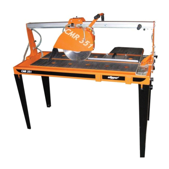
Summary of Contents for Norton clipper CMR 351
- Page 1 CMR 351 OPERATING INSTRUCTIONS...
- Page 3 Declaration of conformity The undersigned manufacturer: SAINT - GOBAIN ABRASIVES S.A. 190, BD J.F. KENNEDY L- 4930 BASCHARAGE Declares that this product: CMR 351230V 70184630429 Masonry Saws: Code: CMR 351 230V U.K. 70184630636 is in conformity with the following Directives: •...
-
Page 5: Table Of Contents
CMR 351 OPERATING INSTRUCTIONS AND SPARE PARTS LIST Basic Safety Instructions Symbols Machine plate Safety instructions for particular operating phases Machine description Short description Purpose of use Layout Technical Data Assembly and commissioning Feet and side extension assembly Tool assembly Electrical connections Starting the machine Water cooling system... -
Page 6: Basic Safety Instructions
1 Basic Safety Instructions The CMR 351 is exclusively designed for the cutting of construction products mainly on construction sites. Uses other than the manufacturer's instructions shall be considered as contravening the regulations. The manufacturer shall not be held responsible for any resulting damage. Any risk shall be borne entirely by the user. -
Page 7: Machine Plate
Immediately remove damaged or badly worn blades, as they endanger the operator whilst rotating. • Only fit NORTON diamond blades to the machine! The use of other tools can damage the machine! • Attention is drawn to the use of BS2092 safety goggles in conformity with specified Processes No.8 of the Protection of Eyes Regulation 1974, Regulation 2(2) Part 1. -
Page 8: Machine Description
As with all other NORTON products, the operator will immediately appreciate the attention given to detail and quality of materials used in construction. The machine and its component parts are assembled to high standards assuring long life and minimum maintenance. - Page 9 ensure that the rail (4) is parallel to the table (8). The rail assembly can also be tilted to 45º to make bevel cuts. The rail guides the cutting head (6) over the table. Blade guard (5) Jig-welded steel construction with 350mm-diameter blade capacity, which offers maximum operator protection and increased visibility of the work piece.
-
Page 10: Technical Data
3.2 Tool assembly Only NORTON blades with a maximum diameter of 350 mm can be used with the CMR 351. All tools used must be selected with regard to their maximum permitted cutting speed for the machine’s maximum permitted rotation speed. -
Page 11: Electrical Connections
• Remove the outer flange. • Clean the flanges and blade shaft and inspect for wear. • Mount the blade on the shaft ensuring that direction of rotation is correct. Wrong direction of rotation blunts the blade quickly. • Replace outer blade flange. •... -
Page 12: Transport And Storing
4 Transport and storing 4.1 Securing for transport Before transporting or lifting the machine, always remove the blade and empty the water pan. Also lock the cutting head on the rail. To do so, move the head in the middle of the rail and tighten the knob screw until the cutting head is secured on the rail. -
Page 13: General Advice For The Cutting
• Lower the cutting head to the desired cutting depth (in “through cutting”, lower cutting head until blade periphery reaches max. 3mm under the surface of the conveyor cart) by means of the handle over the cutting head • Fix position by tightening the clamping device over the blade guard •... -
Page 14: Maintenance And Servicing
6 Maintenance and servicing To ensure a long-term quality from the cutting with the CMR 351, please follow the maintenance plan below: Whole machine Visual control (general aspect, watertightness) Clean Flange and blade fixing devices Clean Motor cooling fans Clean Water pump Clean Water pan... -
Page 15: Faults: Causes And Cures
Faults: causes and cures Fault-finding procedures Should any fault occur during the use of the machine, turn it off, and isolate it from the electrical supply. Any works dealing with the electrical system or supply of the machine can only be carried out by a qualified electrician. -
Page 16: Circuit Diagram
Circuit diagram... -
Page 17: Customer Service
Holland: 0 8000 22 02 70 Tel : 0845 602 6222 e-mail: sales.nlx@saint-gobain.com Free fax : 0800 622 385 e-mail : nortondiamonduk@saint-gobain.com Czech Republic Norton Diamantove Nastroje Sro Austria Vinohrdadska 184 Saint-Gobain Abrasives GmbH CS-13000 PRAHA 3 Telsenberggasse, 37 Tel: 0042 0267 13 20 21... - Page 18 Tel: 0034 948 30 3000 Tel: 0048 22 868 29 36 Fax: 0034 948 30 6042 Tel/Fax: 0048 22 868 29 27 e-mail:Comercial.sga-apa@saint-gobain.com e-mail: norton-diamond@wp.pl Italy Saint-Gobain Abrasivi S.p.A. Via per Cesano Boscone, 4 I-20094 CORSICO-MILANO Tel: 0039 02 44 851...
- Page 20 SAINT-GOBAIN ABRASIVES 190, Bd. J. F. Kennedy L-4930 BASCHARAGE LUXEMBOURG Tel.: ++352 50401-1 Fax: ++352 501633 e-mail: sales.nlx@saint-gobain.com www.construction.norton.eu 28.04.2009...
Need help?
Do you have a question about the clipper CMR 351 and is the answer not in the manual?
Questions and answers