Table of Contents
Advertisement
Quick Links
Advertisement
Table of Contents

Subscribe to Our Youtube Channel
Related Manuals for Norton C1320P


Summary of Contents for Norton C1320P
- Page 1 OWNERS MANUAL MEDIUM CONCRETE SAWS MODEL: C1320P FORM C1320P rev 9-2010...
-
Page 2: Warranty Information
In no event shall Norton be liable for consequential or incidental damages arising out of the failure of any product to operate properly. Integral units such as gasoline engines, electric motors, batteries, tires, transmissions, etc., are excluded from this warranty and are... -
Page 3: Table Of Contents
Table of Contents CONTENTS PAGE Warranty Information I. Preparation A. Safety Precautions B. Assembly C. Concrete Saw Specifications II. Operation A. Blade Installation 9-11 B. Changing the Blade Side 12-14- C. Engine Operation 12-14 D. Starting The Engine 14-16 E. Water Supply F. -
Page 4: Preparation
I. PREPARATION A. Safety Precautions Important! The following safety precautions must always be observed. Hazard Symbols Fuel (gasoline) is extremely flammable and its vapors can explode if ignited. Store gasoline only in approved containers, in well-ventilated, unoccupied approved areas, and away from sparks or flames. -
Page 5: Dust And Silica Warning
Dust and Silica Warning Grinding/cutting/drilling of masonry, concrete, metal and other materials can generate dust, mists and fumes containing chemicals known to cause serious or fatal injury or illness, such as respiratory disease, cancer, birth defects or other reproductive harm. If you are unfamiliar with the risks associated with the particular process and/or material being cut or the composition of the tool being used, review the material safety data sheet and/or consult your employer, the material manufacturer/supplier, governmental agencies such as OSHA and... - Page 6 1. Before mounting any blade on the saw, the blade should be inspected for any damage which might have occurred during shipment, handling or previous use. 2. The blade collars and arbors should be cleaned and examined for damage before mounting the blade. 3.
-
Page 7: Assembly
Inspect the saw for shipping damage. If any damage is found, contact the shipper immediately and file a freight claim. Norton Clipper is not responsible for any freight-related damages. Remove the saw from the pallet. Reverse the position of the handlebars so that the handle bar sticks out towards the operator. -
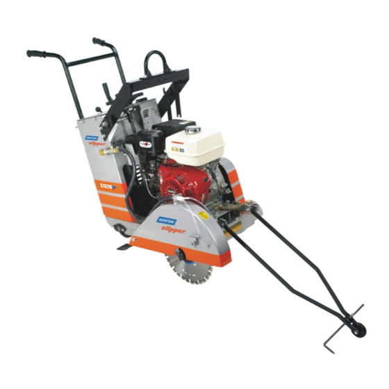
Page 8: Concrete Saw Specifications
C. C1320P Concrete Saw Specifications Dimensions/Weight C1320P 56 inch (1142 mm) Length (Transport) 26 inch (660 mm) Width 40 inch (1016 mm) Height 310 (141kg) Weights Engine Honda Engine Mfg. GX390 Model GX390K1QXC9 Spec No. Single Cylinder 4 Cycle Engine Type 13 hp (9.5kW) @ 3,600 rpm... -
Page 9: Operation
II. OPERATION Read and understand this manual before running or using the machine! A. Installing the Blade 1. Insure that the Ignition Power Key Switch is in the OFF position and then disconnect the spark plug. 2. Remove the blade shaft nut, (NOTE: Operator’s Right side is a left hand thread and the Operator’s Left side is right hand thread), and remove the outside collar. -
Page 10: Blade Installation
In addition check that the blade is the correct specification for the application. For Best Performance Use Only Norton Diamond Blades Specified For the Material Being Cut. 5. Place the blade on the blade shaft, lining up the drive pin hole in the blade with the drive pinhole in the inside collar. - Page 11 Observe rotation arrow on blade and do not exceed maximum RPM stamped on blade. NOTE: Organic bonded blades (A) must have a blotter. The blotter (B) must extend past the blade collar contact area as shown. Blades Use Only Norton Diamond Blades...
-
Page 12: Changing The Blade Side
B. Changing the Blade Side: 1. Insure that the Ignition Power Key Switch is in the OFF position and then disconnect the spark plug. 2. Remove the blade shaft nut, (NOTE: Operator’s Right side is a left hand thread and the Operator’s Left side is right hand thread), and remove the outside collar. - Page 13 6. Remove the Blade Shaft Guard by removing the Blade Shaft Guard retaining bolts. See Blade Shaft Guard Removal diagram below. Blade Shaft Guard Blade Shaft Guard Removal 7. Place the blade on the blade shaft, lining up the drive pin hole in the blade with the drive pinhole in the inside collar.
-
Page 14: Engine Operation
12. Remove the Pointer and reattach it to the Operators Left hand side of the machine. NOTE: Reverse the orientation of the Pointer 13. Reconnect the spark plug. C. Engine Operation Prior to attempting to operate the engine, read the information contained in the engine owner's manual. -
Page 15: F. Controls
Before starting, insure that the blade is properly installed, all guards are in place and in safe operating condition, and that the Blade is not in contact with any surface or object. Also verify that the area where the work is to be preformed is clean, safe, and has proper ventilation and lighting. -
Page 16: Water Supply
As the engine warms up, gradually move the choke Pull the starter grip lightly until you feel resistance, lever to the OPEN position. Position the throttle then pull briskly. CAUTION: Do not allow the starter control lever for the maximum engine speed (full grip to snap back against the engine. - Page 17 Engine Ignition Switch: The Engine Ignition Switch allows the operator to start and stop the engine. The C1320P is equipped with a manual start engine. The engine will not start unless the Ignition Key is in the On position, Emergency Kill...
-
Page 18: Operating The Saw
Tachometer/Hour Meter: The Tachometer/Hour Meter shows the engine RPM only when the Engine is running. The total Engine operating hours (run time) are shown when the Engine is turned off. Emergency Kill Switch: The Emergency Kill Switch will stop the engine when depressed. The engine will not restart until the Emergency Kill Switch is pulled out. -
Page 19: Cutting Technique
11. Slowly lower the blade by rotating the hand wheel clockwise until the desired depth of cut is reached. Use a reasonable rate of feed. A reasonable rate of feed will depend on depth of cut, material, and blade. Normal cutting speeds should be between 2 ft/min in very hard material and up to 10 ft/min in softer materials. -
Page 20: Lead-Off Adjustment
Additional Guide Lines For Sawing: Understand and follow all of the instructions in this owner’s manual. If wet cutting, turn on the water supply so that there is a minimum of 4-6 gallons per minute of water flow!! ... -
Page 21: Maintenance
If the charts have any differences, follow the chart in the Honda Engine Manual. Norton does not warranty the engine. If any warranty or service of the engine is required contact your nearest Honda service center, or from the Internet: http://www.honda-engines.com/home.htm... - Page 22 Always refer to the engine manual for more detailed information on checking the oil, changing oil, and oil capacity, air filter changes, and fuel type to use. Use only Honda air filters. Do not clean the air filter with gasoline or other flammable solvents.
-
Page 23: Engine Warranty
HONDA TECHNICAL & CONSUMER INFORMATION Warranty Service Information Servicing dealership personal are trained professionals. They should be able to answer any questions you may have. If you encounter a problem that your dealer does not solve to your satisfaction, please discuss it with the dealership’s management. -
Page 24: Bearings
B. Bearings Re lubrication type bearings must be relubricated daily to assure long life. The grease used should conform to the NLGI grade two consistencies and be free of any chemical impurities such as free acid or free alkali, dust rust, metal particles or abrasives. -
Page 25: V-Belts
C. V-Belts Warning: Never make adjustments to belts or pulleys while engine is running! 1. The best tension for a belt drive is the lowest tension at which the belts will not slip under full load. 2. Simply take up the drive until the belts are snug in the grooves. -
Page 26: Depth Control
Main Causes of Belt Failures: Premature Belt failure can be attributed to the following issues: Tension (too much or too little), Pulley Misalignment, Damaged Pulleys, Improper Handling or Storage, Incorrect Blade Specification for Material Being Cut, and Cutting Too Deep. Symptom Possible Cause Corrective Action... - Page 27 The bearing used to support the raising screw should be checked after each use to make sure it is turning freely and lubricated. If the bearing requires re lubrication lithium base grease is recommended. Over tightening the Hand Wheel during the raising or lowering the Saw will damage the raise screw or Bearing.
-
Page 28: Electrical Diagram 13Hp Manual Start
E. ELECTRICAL DIAGRAM C1320P: 13HP Manual Start Models Only Honda Engine Honda Part# 36100-ZE1-015 Kill SGA# 227115 Switch (BL) (BL) BL (238038) BL (238039) Oil Alert Transistorized Oil Level Unit Ignition Switch Spark Plug Unit... -
Page 29: Parts List Section
Wear Parts (W). For best performance and life Genuine Norton Clipper replacement parts should always be used. Changes to part specifications, are subject to change with out notice.. -
Page 30: Assembly Drawings/Service Parts Listing
C1320P Frame Group... - Page 31 C1320P Frame Group Item Part No UPC No Description Type NOTES 238171 70184628065 LIFT FRAME 238175 LIFT FRAME HOOK 70184628066 8041051 SCR 3/8-16 X 1 1/4 HEX HD CAP 70184649901 8177012 WASHER 3/8 SPRING LOCK 70184650149 8172009 WASHER 3/8 SAE...
-
Page 32: Raise Axle Group
C1320P Raise Axle Group... - Page 33 C1320P Raise Axle Group Item Part No UPC No Description Type NOTES 238134 70184628082 RAISE AXLE MOUNT Sold as Each. 238129 REAR AXLE BUSHING 70184628085 238124 REAR WHEEL SPACER 70184628272 8172015 WASHER 3/4 SAE 70184650129 WHEEL 6 X 2 X 3/4 W/ROLLER Sold as Each.
-
Page 34: Blade Shaft And Engine Group
C1320P Blade Shaft & Engine Group... - Page 35 C1320P Blade Shaft & Engine Group Item Part No UPC No Description Type NOTES 238179 70184628084 BLADE SHAFT 227159 TIGHT COLLAR RIGHT SIDE 70184673904 LEFT HAND THREAD 227190 TIGHT COLLAR LEFT SIDE 70184674352 RIGHT HAND THREAD 227247 LOOSE COLLAR OUTER FLANGE...
- Page 36 C1320P Blade Guard and Water System Group...
-
Page 37: Blade Guard And Water System Group
C1320P Blade Guard and Water System Group Item Part No UPC No Description Type NOTES N1D0082 70184659115 HOSE SWIVEL N1C0021 70184659097 WATER VALVE 1/2" 9602012 70184626501 HOSE BARB 1/2" x ½”MPT N1C0113 70184659232 HOSE CLAMP 8041006 70184649879 SCR 1/4-20 X 1 HEX HD CAP... -
Page 38: Controls And Console Group
C1320P Controls and Console Group... - Page 39 C1320P Controls and Console Group Item Part No UPC No Description Type NOTES 238120 70184627887 HANDLE BAR N1C0004 70184659110 HANDLE BAR GRIP 8041006 70184649879 SCR 1/4-20 X 1 HEX HD CAP 8177010 70184650144 WASHER 1/4 SPRING LOCK 8172007 70184650120 WASHER 1/4 SAE...
-
Page 40: Depth Adjustment Group
19 21 C1320P Depth Adjustment Group... - Page 41 C1320P Depth Adjustment Group Item Part No UPC No Description Type NOTES 238164 70184628181 DEPTH SCREW TUBE 238234 70184628182 GREASE ZERK 1/8 407035 70184682129 SCR 1/4-20 X 1/4 SET CUP 238163 70184628265 NUT 3/4-10 HEX HEAD 238165 70184628183 RAISE SCREW...
-
Page 42: Optional Water Tank Group
To Blade Guard C1320P Optional Water Tank Group... - Page 43 C1320P Optional Water Tank Group Item Part No UPC No Description Type NOTES INCLUDES: Items 1, and 3 -NA- 238001 70184628014 WATER TANK KIT to 10 83357 00310007011 WATER TANK W/CAP 82794 CAP FOR WATER TANK 00310006560 238174 BRACKET FOR WATER TANK...
-
Page 44: Contact Information
Saint-Gobain Abrasives 2770 West Washington Stephenville, TX 76401 Phone: 254-918-2310 Fax: 254-918-2312...
Need help?
Do you have a question about the C1320P and is the answer not in the manual?
Questions and answers