
Related Manuals for Norton Clipper C1418P


Summary of Contents for Norton Clipper C1418P
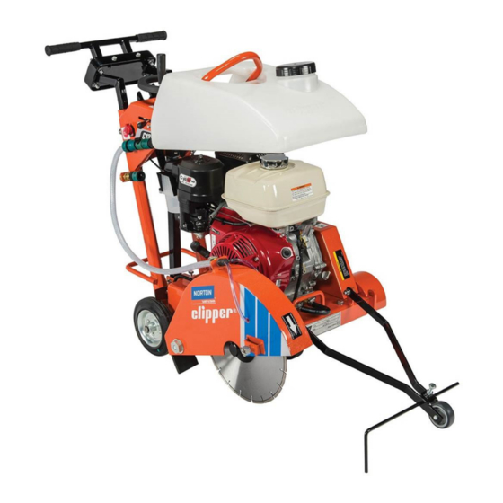
- Page 1 OWNERS MANUAL Small Concrete Saw MODEL: C1318P C1418P FORM: C1318P-C1418P rev 2-2022...
- Page 2 In no event shall Norton be liable for consequential or incidental damages arising out of the failure of any product to operate properly.
-
Page 3: Table Of Contents
Blade Shaft Group 30-31 Belt Tensioning Group Engine Mount Group Main Frame Group Water Control Group 35-36 Front Pointer Group Decals 38-42 Read Owner’s Manual Before Use Safety Alert Symbol: Information Following This Symbol Is Very Important Use Only Norton Diamond Blades... -
Page 4: Preparation
I. PREPARATION A. Safety Precautions Important! The following safety precautions must always be observed. Hazard Symbols Fuel (gasoline) is extremely flammable and its vapors can explode if ignited. Store gasoline only in approved containers, in well-ventilated, unoccupied approved areas, and away from sparks or flames. -
Page 5: Dust And Silica Warning
Dust and Silica Warning Grinding/cutting/drilling of masonry, concrete, metal and other materials can generate dust, mists and fumes containing chemicals known to cause serious or fatal injury or illness, such as respiratory disease, cancer, birth defects or other reproductive harm. If you are unfamiliar with the risks associated with the particular process and/or material being cut or the composition of the tool being used, review the material safety data sheet and/or consult your employer, the material manufacturer/supplier, governmental agencies such as OSHA and... - Page 6 1. Before mounting any blade on the saw, the blade should be inspected for any damage which might have occurred during shipment, handling or previous use. 2. The blade collars and arbors should be cleaned and examined for damage before mounting the blade. 3.
-
Page 7: Assembly
Inspect the saw for shipping damage. If any damage is found, contact the shipper immediately and file a freight claim. Norton Clipper is not responsible for any freight-related damages. Remove the saw from the pallet. Reverse the position of the handlebars so that the handle bar sticks out towards the operator. -
Page 8: C1318P And C1418P Series Concrete Saw Specifications
C. C1318P and C1418P Series Concrete Saw Specifications Dimensions/Weight C1318P C1418P Length (Working) 45.66” (1160 mm) Length (Transport) 33.50” (850 mm) Width 39.50” (1003 mm) Height 39” (990 mm) Weight 220 lbs (100 kg) Engine Engine Mfg. Honda Kohler Model GX390 CH440 Manufacturers Spec No. -
Page 9: Engine
D. Engine Prior to attempting to operate the engine, read the information contained in the engine owner's manual. An engine owner’s manual is supplied with every gasoline powered concrete saw. 1. Check Oil: Add oil if low. Refer to the engine owner's manual for the recommended SAE viscosity grades. -
Page 10: Starting The Engine
4. Place the blade on the blade shaft, lining up the drive pin hole in the blade with the drive pinhole in the inside collar. For Best Performance Use Only Norton Diamond Blades Specified for the Material Being Cut. 5. Slide the outside blade shaft collar onto the blade shaft. The drive pin on the outside collar must project through the drive pin hole in the blade and into the inside collar. -
Page 11: C1418P 14Hp Kohler
Pull The Throttle Control Slightly to the Rear to Place the Console ON/OFF switch to the ON provide some engine throttle. position C1318P Honda Powered C1318P Honda Powered As the engine warms up, gradually move the choke lever to the OPEN position. Position the throttle Pull the starter grip lightly until you feel resistance, control lever for the maximum engine speed (full then pull briskly. - Page 12 6. Verify that the air cleaner components, all shrouds, machine blade guard, machine belt guard are in place and securely fastened. Before starting, insure that the blade is properly installed, all guards are in place and in safe operating condition, and that the Blade is not in contact with any surface or object.
-
Page 13: Water Supply
Place the engine ON/OFF switch to the ON position and NOTE: The Engine ON/OFF Switch is located Move the Engine Throttle Slightly to the Left on the front of the Engine. C1418P Kohler Powered C1418P Kohler Powered Pull the starter grip lightly until you feel resistance, then pull briskly. -
Page 14: Operating The Saw
Water Tank on saw: This supply is designed for use with dry blades to keep the dust levels down. The tank will not supply the proper water flow rates when used with wet cut only blades. Do not drink the water from this tank. -
Page 15: Cutting Technique
10. When the end of the cut is reached, slowly raise the blade out of the cut by rotating the Hand Wheel counter-clockwise until the blade is at least one (1) inch above the ground. 11. Only move the saw in reverse with the blade in the raised position. 13. -
Page 16: Maintenance
Or visit the engine manufacturer’s web site for details. If the charts have any differences, follow the chart in the Engine Manual. Norton does not warranty the engine. If any warranty or service of the engine is required contact your nearest Engine Service Center, or from the Internet: http://www.honda-engines.com... - Page 17 Honda Engine Oil Viscosity vs. Ambient Temperature. Honda Engines Only. Always refer to the engine manual for more detailed information on checking the oil, changing oil, and oil capacity, air filter changes, and fuel type to use. Use only Honda air filters. Do not clean the air filter with gasoline or other flammable solvents.
-
Page 18: C1418P Kohler Powered
C1418P Kohler engine (refer to Kohler Engine Owner's manual for complete maintenance.) Check the engine oil level before each use when the engine is cool and the engine is level. Add oil if the level is low. The oil level should be within the operating range (see the engine owner’s manual for details). -
Page 19: Dry Cutting Engine Maintenance (Honda And Kohler)
Kohler Engine Oil viscosity vs. ambient Temperature. Kohler Engines Only. Dry Cutting Engine Maintenance (Honda and Kohler) When operating the engine in dry cutting or dusty environments the following is required: Engine oil changed more often. Every 50 hours (or more often if conditions require) clean all of the engine cooling fins. -
Page 20: V-Belts
Shaft Size Maximum Grease Capacity of Bearing Chamber in Ounces 1/2"' to 3/4" 7/8" to 1-3/16" 1-1/4" to 1-1/2" Improper Maintenance Of Bearings Is Not Covered By Any Warranty. Over Lubrication Will Damage A Bearing. Grease Protruding From The Sides Of The Bearing Is A Sign Of Over Lubrication. - Page 21 Engine M10 Mounting Bolt, Belt Guard qty =4. Note one (1) per corner of engine. Belt Tensioning Assembly M10 Belt Guard Retaining Hardware, qty=3. NOTE: One (1) Bolt is on the front of the Belt Guard Figure: C1318P/C1418P Belt Tensioning System 1.
- Page 22 6. To apply tension to the Belts, tighten (turn clockwise) the rear M10 Jam Nut until the required Belt Tension is achieved. To loosen the Belts, turn the front M10 Jam Nut counter clockwise until the required Belt Tension is achieved. (See Figure: C1318P/C1418P Belt Tensioning Jam Nut Directions).
- Page 23 To align the Pulleys: 1. Review the locations of the C1318P/C1418P Belt Tensioning system before proceeding. (See Figure: C1318P/C1418P Belt Tensioning System on page 15). 2. Remove the Belt Guard by loosening and removing the three M10 Belt Guard Retaining Bolts.
-
Page 24: Depth Control
D. Depth Control The depth control (raising screw) consists of a threaded rod, which feeds into a steel nut. In order to keep the two parts working smoothly it is necessary to keep the rod free from dirt and sludge as much as possible. Cleaning the threaded rod with a rag after each use will prevent sludge from collecting in the tube assembly and protect the threads. -
Page 25: Wiring Diagrams: C1318P And C1418P
F. Wring Diagram: C1318P and C1418P C1318P 13 HP GX390 Honda Only C1418P 14 HP CH440 Kohler Only... -
Page 26: Parts List Section
Any wear due to normal use of the machine will not be considered as a case of warranty for items designated as Wear Parts (W). For best performance and life Genuine Norton Clipper replacement parts should always be used. Changes to part specifications,... -
Page 27: Parts Drawing And Service Parts List
Depth Control and Depth Lock Group Front Of Machine Item UPC No Part No Description Type NOTES 00310004840 HANDWHEEL AND HANDLE Includes: Handle and Hardware 076357 00310004966 NUT HANDWHEEL Includes: Acorn Nut, and Washers 076843 70184643370 SPACER 28x22x22 048620 00310327609 WHEEL HOOK + SPRING CS 501 Includes: Hook, Spring, and Nut 232349... -
Page 28: Handle Bar Group
Handle Bar Group Item UPC No Part No Description Type NOTES Includes: Handle Bar Frame (Upper HANDLE BAR ASSEMBLY 70184643284 and Lower), Hand Grips (2), Vibration 232313 C1318P/C1418P Absorber Kit (4), and Hardware 00310004190 GRIP HANDLE Sold As Each. Appearance May Vary 072097 70184600809 SCR M10 X 25 8.8 DIN933... -
Page 29: Blade Guard Group
Blade Guard Group Front Of Machine Item UPC No Part No Description Type NOTES BLADE GUARD ASSEMBLY Includes: Items 2 (2x), 3 (2x), 4 (2x), 5 70184643285 232317 C1318P/C1418P (2x), 6, 7. 8, and 9 70184628500 PIN GUARD LOCK 238222 70184628501 RING GUARD LOCK 238223... - Page 30 Blade Shaft Group Front Of Machine...
-
Page 31: Blade Shaft Group
Blade Shaft Group Item UPC No Part No Description Type NOTES Includes: Pulley, Bushing, Set 70184643291 232352 PULLEY ENGINE KIT C1318P/C1418P Screws, and Key 70184643371 232344 BELT POLY-V 10 PK 698MM Includes: Items 4, 5 (2x), 6, 7, 8, 9 SHAFT BLADE ASSEMBLY 70184643372 232357... -
Page 32: Belt Tensioning Group
Belt Tensioning Group Item UPC No Part No Description Type NOTES ENGINE MOUNTING KIT Includes: Front, Rear Motor Mounts, 70184643374 232330 W/HARDWARE C1318P/C1418P and Hardware Type: S = Service Part, W = Wear Part, All Parts Are Sold As Individual (each) Unless Noted Otherwise... -
Page 33: Engine Mount Group
Engine Mount Group Front Of Machine Item UPC No Part No Description Type NOTES 00310007025 GUARD BELT ASSY Includes: Belt Guard and Hardware 083371 BLADE SHAFT GUARD ASSMEBLY Includes: Blade Shaft Guard and 70184643375 232358 C1318 Hardware FRAME WELD MOTOR 00310007023 Includes: Engine Mount Only 083369... -
Page 34: Main Frame Group
Main Frame Group Front Of Machine Item UPC No Part No Description Type NOTES 70184643376 MAIN FRAME WELDMENT C318P Frame Only 232323 Includes Items: 3 (2x), 5 (6x), 6 (2x), 7 00310006550 AXLE REAR COMPLT W/WHEELS 082784 (2x), and 11 00310005129 080297 BUSH INNR MOT PIVOT (2) -
Page 35: Water Control Group
Water Control Group Front Of Machine... - Page 36 Water Control Group Item UPC No Part No Description Type NOTES WATER TANK COMPLETE Includes: Water Tank and Stopper 00310351798 232356 C1318P/C1418P/CS451 (Cap) STOPPER WATER TANK 00310006560 082794 C13/C13P18/C1318P/C1418P Includes: Valve Assembly w/Hose Adapter (1), Male Quick Detach x 3/4" Garden Hose (1), Female Quick Detach (1) x ¾”...
-
Page 37: Front Pointer Group
Front Pointer Group Front Of Machine Item UPC No Part No Description Type NOTES POINTER ASSY Includes: Front Pointer Rod, Pointer 00310024051 232127 C13PC18/C13P18/C1318P/C1418P Frame, Wheel, and Hardware WHEEL POINTER W/HARDWARE 00310004622 Front Wheel and Hardware 232126 C13P18/C1318P/C1418P POINTER ROD 00310004244 Front Pointer Rod Only 232125... -
Page 38: Decals
PN: 233460 C1418P Operator’s DECAL MODEL C1418P 70184631618 RIGHT OPERATOR RIGHT PN: 233904 Operators Right and Left DECAL NORTON CLIPPER LOGO Sides of Blade Guard ALL 70184631637 8.93x4.79” Machines. PN: 233455 Blade Guard Nose DECAL NOSE STRIPE Operator’s RIGHT Side... - Page 39 C1318P and C1418P Decals Operator’s Left Side Operator’s Left Side Description NOTES Image DECAL MODEL C1318P C1318P Operator’s LEFT 70184608607 OPERATOR LEFT PN: 233461 DECAL MODEL C1418P C1418P Operator’s LEFT 70184631619 OPERATOR LEFT PN: 233905 DECAL NOSE STRIPE Blade Guard Nose Operator’s 70184632231 OPERATOR'S LEFT LEFT Side ALL Models...
- Page 40 C1318P and C1418P Decals Front and Rear Front Rear Front Description NOTES Image Front of Blade Guard ALL DECAL DIRECTIONAL ARROW 70184632232 Models BLADE GUARD PN: 233462 Front of Blade Guard ALL 70184653268 DECAL GUARD LIFT CAUTION Models PN: 108850 -NA- -NA- PLATE SERIAL NUMBER...
- Page 41 C1318P and C1418P Decals Console Console Description NOTES Image Lifting Bale Brace 70184674481 DECAL SAFETY GEAR CAUTION ALL Models PN: 227234 Console Top 70184680834 DECAL CONSOLE C1318P/C1418P ALL Models PN: 232070 Console Top Above Throttle 70184632233 DECAL THROTTLE C1318P C1318P Console Top Above Throttle 70184631617 DECAL THROTTLE C1418P...
- Page 42 ALL Models PN: 227237 Rear of Belt Guard 70184674633 DECAL CAUTION BELTS ALL Models PN: 227238 Center of Belt Guard ALL DECAL NORTON CLIPPER LOGO 70184632228 Machines. 8.93x4.79” PN: 233384 Front of Belt Guard 70184674634 DECAL CAUTION DISCONNECT ALL Models PN: 227239 Top Operator’s Right Side of...
- Page 43 NOTES:...
- Page 44 Saint-Gobain Abrasives 2770 West Washington Stephenville, TX 76401 Phone: 254-918-2310 Fax: 254-918-2312...
Need help?
Do you have a question about the Clipper C1418P and is the answer not in the manual?
Questions and answers