Table of Contents
Advertisement
Quick Links
Advertisement
Table of Contents

Related Manuals for Pepperl+Fuchs PGV F200A R4-V19 Series


Summary of Contents for Pepperl+Fuchs PGV F200A R4-V19 Series
- Page 1 PGV...-F200/-F200A...-R4- Incident Light Positioning System Manual...
- Page 2 Phone: +49 621 776 - 0 E-mail: info@de.pepperl-fuchs.com North American Headquarters Pepperl+Fuchs Inc. 1600 Enterprise Parkway Twinsburg, Ohio 44087 Phone: +1 330 425-3555 E-mail: sales@us.pepperl-fuchs.com Asia Headquarters Pepperl+Fuchs Pte. Ltd. P+F Building 18 Ayer Rajah Crescent Singapore 139942 Phone: +65 6779-9091 E-mail: sales@sg.pepperl-fuchs.com https://www.pepperl-fuchs.com...
-
Page 3: Table Of Contents
PGV...-F200/-F200A...-R4-V19 Contents Safety .......................... 5 Introduction ....................5 1.1.1 Content of this Document ....................5 1.1.2 Manufacturer ........................5 1.1.3 Target Group, Personnel ..................... 5 1.1.4 Symbols Used ........................6 Product Description ....................7 Use and Application ..................7 The RS-485 Interface ..................9 LED Indicators and Controls .............. - Page 4 PGV...-F200/-F200A...-R4-V19 Contents Code Cards for External Parameterization..........50 6.1.1 Code Cards with Special Functions .................. 51 6.1.2 Code Cards for Setting the Read Head Address............... 53 6.1.3 Code Cards for Adjusting the Resolution ................55 6.1.4 Code cards for setting the transfer rate ................57 6.1.5 Code cards for adjusting the terminator ................
-
Page 5: Safety
Control drawings • Instruction manual • Other documents 1.1.2 Manufacturer Pepperl+Fuchs Group Lilienthalstraße 200, 68307 Mannheim, Germany Internet: www.pepperl-fuchs.com 1.1.3 Target Group, Personnel Responsibility for planning, assembly, commissioning, operation, maintenance, and dismount- ing lies with the plant operator. Only appropriately trained and qualified personnel may carry out mounting, installation, com- missioning, operation, maintenance, and dismounting of the product. -
Page 6: Symbols Used
PGV...-F200/-F200A...-R4-V19 Safety 1.1.4 Symbols Used This document contains symbols for the identification of warning messages and of informative messages. Warning Messages You will find warning messages, whenever dangers may arise from your actions. It is mandatory that you observe these warning messages for your personal safety and in order to avoid prop- erty damage. -
Page 7: Product Description
(AGV) are to be positioned pre- cisely at marked positions along a given lane. The read head forms part of the positioning system in the Pepperl+Fuchs incident light pro- cess. The read head's features include a camera module and an integrated illumination unit. - Page 8 PGV...-F200/-F200A...-R4-V19 Product Description Tag Mode In addition to the tracking, you can use the read head in tag mode. The read head detects Data Matrix tags, which are typically glued onto the floor in a grid. The individual Data Matrix tags are numbered consecutively and include position information.
-
Page 9: The Rs-485 Interface
PGV...-F200/-F200A...-R4-V19 Product Description The RS-485 Interface The read head is equipped with an RS-485 interface for communication purposes, i.e., param- eterizing the read head functions or reading out current process data during operation. This interface is operated in 8-E-1 mode and fitted with a terminator that can be activated or deacti- vated by parameterizing the sensor head accordingly. -
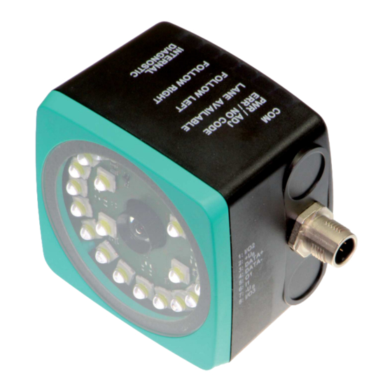
Page 10: Led Indicators And Controls
PGV...-F200/-F200A...-R4-V19 Product Description LED Indicators and Controls The read head is equipped with seven indicator LEDs for carrying out visual function checks and rapid diagnostics. The read head is equipped with two buttons at the back for activating parameterization mode. Button 1 is labeled ADJUST. Button 2 is labeled CONFIG. ADJUST CONFIG Figure 2.3... - Page 11 = 2 Hz for 1 sec flash Time lock for buttons disabled Lights up Internal error Return to Pepperl+Fuchs Table 2.1 1. LED status has no meaning 2. No lane selected, for example. .see table "Error Codes" on page 40 3. See chapter 4...
-
Page 12: Accessories
If products are used in harsh ambient conditions, appropriate Pepperl+Fuchs accessories can be used to extend the service life of these products. -
Page 13: Installation
PGV...-F200/-F200A...-R4-V19 Installation Installation Mounting the Read Head Mount the PGV... read head on the automated guided vehicle using the four screws on the mounting adapter on the read head. Mount the read head in such a way that the lens with the ring light and camera module are directed toward the colored tape. - Page 14 PGV...-F200/-F200A...-R4-V19 Installation Read Head Dimensions M6 x 9 (4x) 13.8 12.5 Figure 3.1 Housing *-F200-* 94.5 M6 x 9 (4x) Figure 3.2 Housing *-F200A-*...
-
Page 15: Mounting The Colored Tape And Code Tape
Due to the integrated lighting of the read head, some floor colors appear to be different in the camera. If you have problems with the color selection of the colored tapes, please consult your contact at Pepperl+Fuchs. Mounting the Colored Tape Clean the surface of any greasy or oily deposits and dust. - Page 16 PGV...-F200/-F200A...-R4-V19 Installation Cleaning Colored Tape/Code Tape Significant contamination on the colored or code tapes can impair the detection by the read head. Clean the colored and code tapes with isopropanol if necessary. If the contamination is severe, you can use a non-corrosive plastic cleaner, e.g., Caramba®. Note To avoid polishing the surface, do not apply strong pressure when cleaning.
- Page 17 PGV...-F200/-F200A...-R4-V19 Installation Angle Output Note Angles are specified as absolute values. The respective value is calculated from the resolution selected under "Angle Resolution". With a resolution of 0.1°, an angle of 60° is output as 60°/0.1° = 600. The read head detects a change of the angle of the colored tape and the Data Matrix code tape and outputs this value to the controller.
- Page 18 PGV...-F200/-F200A...-R4-V19 Installation Data Matrix code tape The read head detects the absolute angle in relation to the tracked lane with a maximum reso- lution of 0.1°. The angle is specified absolutely relative to the tracked lane, since a Data Matrix code contains tape direction information.
- Page 19 PGV...-F200/-F200A...-R4-V19 Installation Data Matrix code tape The read head indicates the vertical distance of the zero point in relation to the Data Matrix code tape. Figure 3.8 Distance A for Data Matrix code tape Branches The read head detects one lane at the lower edge of the field of vision and two lanes at the upper edge of the field of vision;...
- Page 20 PGV...-F200/-F200A...-R4-V19 Installation The read head can make the following direction decisions based on the lane and possible branches: • Follow left-hand lane • Straight ahead • Follow right-hand lane The direction decision is signaled to the read head via the controller. If there is no direction decision, the read head displays an error message.
- Page 21 PGV...-F200/-F200A...-R4-V19 Installation Figure 3.10 Separate lane branches off/converges Figure 3.11 Same lane branches off/converges Note Direction Decision The direction decision at a branch of a Data Matrix code tape remains in effect until the read head has moved more than 50 cm from the branch. It is not possible to change the direction decision within a branch!
- Page 22 PGV...-F200/-F200A...-R4-V19 Installation Note Priority Data Matrix code tapes and Data Matrix tags have priority over colored tapes or colored lanes. If the read head detects a Data Matrix code tape or Data Matrix tags in the field of view, colored tapes or colored lanes in the field of view are ignored.
- Page 23 PGV...-F200/-F200A...-R4-V19 Installation Note Loss of Information Ensure that Data Matrix codes are not positioned over one another at a branch, as otherwise data may be lost. It is not permitted to create a mixture of lanes made from colored tape and Data Matrix codes at branches or intersections.
- Page 24 PGV...-F200/-F200A...-R4-V19 Installation Distances To ensure that the read head can clearly detect and assign colored tapes and Data Matrix codes, minimum and maximum distances must be observed when creating the lanes. Offset V between position codes of a lane must not be greater than 5 mm. Figure 3.15 Offset: 0 mm ...
- Page 25 PGV...-F200/-F200A...-R4-V19 Installation The distance between the Data Matrix code tapes at a branch or intersection as a separate lane must be between 0 mm and 5 mm. Figure 3.17 Distance: 0 mm D 5 mm The distance between a colored tape and a Data Matrix control code must be between 0 mm and 5 mm.
- Page 26 PGV...-F200/-F200A...-R4-V19 Installation The distance between a Data Matrix position code and a Data Matrix control code must be between 0 mm and 5 mm. 25 mm 25 mm 25 mm Figure 3.19 0 mm D 5 mm A lane can switch from a colored tape to a Data Matrix code tape and back again as often as required.
- Page 27 PGV...-F200/-F200A...-R4-V19 Installation Caution! Alignment The Data Matrix code is not on the center line of the code tape. The code tape is made of silicone-free polyester film. A position marker appears every 100 mm along the lower edge of the code tape (see "Code Tape Dimensions"). This position marker is used for various functions, including precise positioning of the code tape during installation.
- Page 28 PGV...-F200/-F200A...-R4-V19 Installation Data Matrix Code Tapes with a Starting Position of 0 m Order designation Description PGV10M-CA25-0 Code tape, length: 10 m PGV100M-CA25-0 Code tape, length: 100 m Table 3.1 See also data sheet PGV*-CA25-* at www.pepperl-fuchs.com Data Matrix control codes Order designation Description PGV-CC25-001...
- Page 29 PGV...-F200/-F200A...-R4-V19 Installation Data Matrix Tag A Data Matrix tag contains position information in addition to a specific number. A cross in the center of the Data Matrix tag marks the zero point. The X and the Y axes are marked starting from the zero point.
-
Page 30: Electrical Connection
Main Figure 3.24 Color assignment Pepperl+Fuchs female cordsets are manufactured in accordance with EN60947-5-2. When using a type V19-... () female cordset with an open cable end on the Main connection, the col- ors are assigned as follows: Connection pin... - Page 31 PGV...-F200/-F200A...-R4-V19 Installation Shielding Cables The shielding of connection lines is required to suppress electromagnetic interference. Estab- lishing a low resistance or low impedance connection with the protective conductor or equipo- tential bonding circuit is a particularly important factor in ensuring that these interference currents do not become a source of interference themselves.
-
Page 32: Commissioning
PGV...-F200/-F200A...-R4-V19 Commissioning Commissioning Specifying the First Direction Decision To ensure that the read head does not report any error messages after being switched on, a direction decision must be specified. You can control the direction decision via the INPUT_SE- LECTION_DIR_RIGHT and INPUT_SELECTION_DIR_LEFT inputs. See chapter 3.3. Direction decision Error 5 Left... - Page 33 PGV...-F200/-F200A...-R4-V19 Commissioning Following Lane with Better Quality You can parameterize the read head so that it follows the better quality color lane. Example Figure 4.2 1 - Better color lane 2 - Worse color lane Following Lane with More Detailed Position Information You can parameterize the read head so that it follows the Data Matrix code tape that continues the current location information.
-
Page 34: Parameter Assignment
PGV...-F200/-F200A...-R4-V19 Commissioning Parameter assignment The reading head can be adapted to specific requirements through parameterization. The reading head can be parameterized via the interface itself (internal parameterization) or via an optical parameterization code (external parameterization). 4.3.1 Internal Parameterization Using Parameterization Software Internal parameterization of the reader via the USB interface must be started within 10 minutes of the reader being switched on. -
Page 35: External Parameterization Using Code Cards
PGV...-F200/-F200A...-R4-V19 Commissioning 4.3.2 External Parameterization Using Code Cards During external parameterization, the reader scans special code cards optically and configures the relevant parameters. Simply hold the corresponding code cards at the correct distance in front of the lens on the reader. The standard code cards are in the appendix. The following parameters can be configured using code cards: •... -
Page 36: The Code Cards "Cancel", "Use", And "Default
PGV...-F200/-F200A...-R4-V19 Commissioning Note Press button 2 briefly to exit parameterization mode. Any parameter changes that are made but have not yet been saved are discarded. The reader then operates with the last valid parameters that were saved. 4.3.2.1 The code cards "CANCEL", "USE", and "DEFAULT" Holding one of these cards in front of the reading head exits parameterization mode with the following consequences: •... -
Page 37: Operation And Communication
PGV...-F200/-F200A...-R4-V19 Operation and communication Operation and communication Communication via the RS-485 Interface The controller and read head communicate via the RS-485 interface during operation. Make sure that the basic communication settings have been made on the read head, such as setting the read head address and baud rate. -
Page 38: Position Response Telegram
PGV...-F200/-F200A...-R4-V19 Operation and communication 5.1.2 Position Response Telegram A response telegram is 21 bytes long. Bytes 1 and 2 contain the read head address and status information. Response telegram from the read head – lane tracking Bit 8 Bit 7 Bit 6 Bit 5 Bit 4 Bit 3... - Page 39 PGV...-F200/-F200A...-R4-V19 Operation and communication Response telegram from the read head - Data Matrix tag Bit 8 Bit 7 Bit 6 Bit 5 Bit 4 Bit 3 Bit 2 Bit 1 Bit 0 Byte 1 Parity 0 Byte 2 Parity 0 TAG [1] Byte 3 Parity 0...
- Page 40 Warning Messages table. Absolute position in the X direction, unsigned Absolute position in the X direction, signed Absolute position in the Y direction, signed Table 5.3 1. Should you have any questions, please contact Pepperl+Fuchs Error Codes Error code Description Priority No clear position can be determined, e.g., difference between...
- Page 41 1. Unsigned: Fill in the missing upper bits with "0". 2. Signed: Fill in the missing upper bits with the highest bit of the response telegram. Should you have any questions about this, please contact Pepperl+Fuchs.
-
Page 42: Number Of Lanes Lc (Lane Count)
PGV...-F200/-F200A...-R4-V19 Operation and communication 5.1.2.1 Number of Lanes LC (Lane Count) The lane count, LC, indicates the number of found fab or Data Matrix tracks in the reading win- dow. A variety of causes may be responsible if the lane count does not match the expected number of lanes: LC <... -
Page 43: Orientation O
PGV...-F200/-F200A...-R4-V19 Operation and communication 5.1.2.2 Orientation O The orientation O indicates the orientation of the control codes in the reading window. Meaning of Bits Meaning Control code has the same orientation as ascending Data Matrix lane Orientation of control code rotated 90° clockwise in relation to ascending Data Matrix lane Orientation of control code rotated 180°... -
Page 44: Side S
PGV...-F200/-F200A...-R4-V19 Operation and communication 5.1.2.3 Side S Side S specifies the side of the Data Matrix lane on which the control codes are present. Meaning of Bits Meaning No control code is present or found Reserved Control code to the right of the Data Matrix or color lane Control code to the left of the Data Matrix or color lane Not detectable 1. -
Page 45: Position/Lane
PGV...-F200/-F200A...-R4-V19 Operation and communication 5.1.2.4 Position/Lane You can use the following table to draw conclusions on the current section in the reading win- dow from the feedback of the read head regarding Data Matrix TAG, No Lane NL, No X Posi- tion NP, absolute X position XP and the Y position and angle YPS/ANG. -
Page 46: Color Choice Request Telegram
PGV...-F200/-F200A...-R4-V19 Operation and communication Meaning of Bits Meaning Error code 5 Follow right-hand lane Follow left-hand lane Straight ahead Table 5.6 See chapter 4.2 Example Request telegram when read head address = 0 Request Response Description Example 0xE8, 0x17 See "Response Tele- Follow left-hand lane --"0x02"-- gram for Direction... - Page 47 PGV...-F200/-F200A...-R4-V19 Operation and communication Response telegram for color choice Byte/bi Bit 8 Bit 7 Bit 6 Bit 5 Bit 4 Bit 3 Bit 2 Bit 1 Bit 0 Byte 1 Parity Byte 2 Parity Meaning of Bits Meaning Choice of color blue Choice of color green Choice of color red Example...
-
Page 48: Operation Using Control Codes
PGV...-F200/-F200A...-R4-V19 Operation and communication Operation Using Control Codes In numerous positioning system applications, defined processes (= event) must be started at specific positions. This means that the exact positions must be defined via code tapes for posi- tioning, instead of simple colored tapes. In the context of lane tracking, it is advisable to mark branches using control codes to facilitate the control of the direction decision. -
Page 49: Operation Using Repair Tape
PGV...-F200/-F200A...-R4-V19 Operation and communication Operation Using Repair Tape The repair tape is a short code tape one meter in length. The repair tape is used to bridge defective or damaged areas of an existing code tape. 1. Cut the repair tape to the required length 2. -
Page 50: Appendix
PGV...-F200/-F200A...-R4-V19 Appendix Appendix Code Cards for External Parameterization Here, you can find the code cards that enable you to parameterize some basic read head func- tions step by step. For the exact external parameterization procedure . Note When performing external parameterization with code cards, we recommend copying and printing out the relevant pages in this manual and cutting out the code cards. -
Page 51: Code Cards With Special Functions
PGV...-F200/-F200A...-R4-V19 Appendix 6.1.1 Code Cards with Special Functions The following code cards have special functions: • ENABLE • STORE • CANCEL • • DEFAULT Enable Figure 6.1 The code card "ENABLE" is used to activate external parameterization operating mode. Store Store Figure 6.2 The "STORE"... - Page 52 PGV...-F200/-F200A...-R4-V19 Appendix Cancel Cancel Figure 6.3 The "CANCEL" code card discards the modified parameterization and terminates external parameterization operating mode. The read head switches to normal mode and adopts the last valid configuration that was saved. Figure 6.4 The "USE" code card takes over the set configuration volatile in the read head working memory and terminates the external parameterization operating mode.
-
Page 53: Code Cards For Setting The Read Head Address
PGV...-F200/-F200A...-R4-V19 Appendix 6.1.2 Code Cards for Setting the Read Head Address A unique address must be assigned to the read head so that it can be activated via the inter- face. The address range extends from 0 ... 3. Read Head Address 0 Adresse 0 Figure 6.6 The code card assigns address 0 to the read head. - Page 54 PGV...-F200/-F200A...-R4-V19 Appendix Read Head Address 3 Adresse 3 Figure 6.9 The code card assigns address 3 to the read head.
-
Page 55: Code Cards For Adjusting The Resolution
PGV...-F200/-F200A...-R4-V19 Appendix 6.1.3 Code Cards for Adjusting the Resolution Parameterization enables you to assign a position data resolution of 0.1 mm / 1 mm / 10 mm to the read head. Resolution: 0.1 mm Resolution 0.1 mm Figure 6.10 The code card assigns a position data resolution of 0.1 mm to the read head. Resolution: 1 mm Resolution 1 mm... - Page 56 PGV...-F200/-F200A...-R4-V19 Appendix Maximum Length of the Code Tape Resolution of the read head [mm] Maximum length of the code tape [km]...
-
Page 57: Code Cards For Setting The Transfer Rate
PGV...-F200/-F200A...-R4-V19 Appendix 6.1.4 Code cards for setting the transfer rate Parameterization allows you to assign various transfer rates to the reading head for communi- cation via the interface. The following transfer rates are available: • 38400 bit/s • 57600 bit/s •... - Page 58 PGV...-F200/-F200A...-R4-V19 Appendix Transfer rate: 76800 bit/s 76800 Bit/s Figure 6.15 The transfer rate of the read head for communication via the interface is preset to 76800 bit/s. Transfer rate: 115200 bit/s 115200 Bit/s Figure 6.16 The transfer rate of the read head for communication via the interface is preset to 115200 bit/s.
-
Page 59: Code Cards For Adjusting The Terminator
PGV...-F200/-F200A...-R4-V19 Appendix 6.1.5 Code cards for adjusting the terminator Parameterization enables you to switch a terminator on and off in the read head: Terminator: OFF Termination Figure 6.18 The terminator is deactivated. Terminator: ON Termination Figure 6.19 The terminator is connected. -
Page 60: Code Cards For Adjusting Input/Output 3
PGV...-F200/-F200A...-R4-V19 Appendix 6.1.6 Code Cards for Adjusting Input/Output 3 Parameterization enables you to assign various functions to input/output 3 on the read head. The following input/output functions are available: • Input: none • Output: Overspeed • Output: Warning • Output: Fault •... - Page 61 PGV...-F200/-F200A...-R4-V19 Appendix Output 3: Warning Output 3 Warning Figure 6.22 Input/output 3 is defined as an output. This output carries the potential +U as long as a warning message is present in the read head. Output 3: Fault Output 3 Error Figure 6.23 Input/output 3 is defined as an output.
- Page 62 PGV...-F200/-F200A...-R4-V19 Appendix Output 3: No position Output 3 No position Figure 6.25 Input/output 3 is defined as an output. This output carries the potential +U as long as the read head is not reading any position information.
- Page 63 Pepperl+Fuchs Quality Download our latest policy here: www.pepperl-fuchs.com/quality www.pepperl-fuchs.com © Pepperl+Fuchs · Subject to modifications Printed in Germany / DOCT-3707D...
Need help?
Do you have a question about the PGV F200A R4-V19 Series and is the answer not in the manual?
Questions and answers