Table of Contents
Advertisement
Quick Links
Advertisement
Table of Contents

Related Manuals for Pepperl+Fuchs PGV100R-F200-B16 Series


Summary of Contents for Pepperl+Fuchs PGV100R-F200-B16 Series
- Page 1 PGV100R-F200-B16* Incident Light Positioning System Manual...
- Page 2 Phone: +49 621 776 - 0 E-mail: info@de.pepperl-fuchs.com North American Headquarters Pepperl+Fuchs Inc. 1600 Enterprise Parkway Twinsburg, Ohio 44087 Phone: +1 330 425-3555 E-mail: sales@us.pepperl-fuchs.com Asia Headquarters Pepperl+Fuchs Pte. Ltd. P+F Building 18 Ayer Rajah Crescent Singapore 139942 Phone: +65 6779-9091 E-mail: sales@sg.pepperl-fuchs.com https://www.pepperl-fuchs.com...
-
Page 3: Table Of Contents
PGV100R-F200-B16* Contents Introduction........................ 4 Content of this Document ................4 Target Group, Personnel ................4 Symbols Used ....................5 Product Description ....................6 Use and Application ..................6 CANopen Interface ..................7 LED Indicators ....................8 Accessories....................9 Installation........................ 10 Mounting the Read Head................ -
Page 4: Introduction
PGV100R-F200-B16* Introduction Introduction Content of this Document This document contains information required to use the product in the relevant phases of the product life cycle. This may include information on the following: • Product identification • Delivery, transport, and storage •... -
Page 5: Symbols Used
PGV100R-F200-B16* Introduction Symbols Used This document contains symbols for the identification of warning messages and of informative messages. Warning Messages You will find warning messages, whenever dangers may arise from your actions. It is mandatory that you observe these warning messages for your personal safety and in order to avoid prop- erty damage. -
Page 6: Product Description
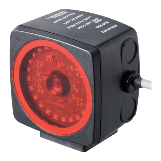
Auto-Guided Transport Systems are to be positioned precisely at marked positions along a given track. The read head forms part of the positioning system in the Pepperl+Fuchs incident light pro- cess. The read head's features include a camera module and an integrated illumination unit, which the read head uses to detect a strip of Data Matrix code tape stuck to the floor to track the lane. -
Page 7: Canopen Interface
PGV100R-F200-B16* Product Description Tag Mode In addition to the lane tracking, you can use the read head in tag mode. The read head detects Data Matrix tags, which are typically glued onto the floor in a grid. The individual Data Matrix tags are numbered consecutively and include position information. -
Page 8: Led Indicators
PGV100R-F200-B16* Product Description LED Indicators The read head is equipped with two indicator LEDs for carrying out visual function checks and quick diagnostics. ADJUST CONFIG Figure 2.3 Display Elements LEDs Color Label Meaning Green/yellow COM STATE Communication active COM ERROR Communication error Green/red POWER ON... -
Page 9: Accessories
If products are used in harsh ambient conditions, appropriate Pepperl+Fuchs accessories can be used to extend the service life of these products. Model number... -
Page 10: Installation
PGV100R-F200-B16* Installation Installation Mounting the Read Head Mount the read head on the auto-guided transport system using the four screws on the mount- ing adapter on the read head. Mount the read head so that the lens with ring light and camera module are aligned toward the floor. -
Page 11: Affixing The Code Tape
PGV100R-F200-B16* Installation Affixing the Code Tape Dimensions of the Code Tape Figure 3.2 Dimensions of the Data Matrix code tape Caution! Alignment The Data Matrix code is not on the center line of the code tape. Caution! Stop edges If you attach another code tape at the end of a previous code tape, the code pattern of 20 mm must be retained. - Page 12 PGV100R-F200-B16* Installation Data Matrix Control Codes Model number Description PGV-CC25-001 Code tape, Control Code 001, length: 1 m PGV-CC25-999 Code tape, Control Code 999, length: 1 m Table 3.2 Data Matrix control codes Affixing the Code Tape Clean the surface of any greasy or oily deposits and dust. Ensure that the surface is dry, clean, and stable.
- Page 13 PGV100R-F200-B16* Installation Cleaning the Code Tape Significant contamination on code tapes can impair detection by the read head. Clean the code tapes with isopropanol if necessary. If the contamination is severe, you can use a non-corrosive plastic cleaner, e.g., Caramba®. Note To avoid polishing the surface, do not apply strong pressure when cleaning.
- Page 14 PGV100R-F200-B16* Installation Distance Output The read head detects the distance from the zero point in the Y direction a Data Matrix code tape and transmits this value to the control panel. The reader indicates the vertical distance of the zero point in relation to the Data Matrix code tape.
- Page 15 PGV100R-F200-B16* Installation Figure 3.6 Distances Behavior of the Read Head at Branches and Curves The read head behaves differently depending on the type of branch and the specified lane. The read head must know the upcoming direction decision. A second lane branches off to the left from the straight lane: The read head follows the straight lane if the direction decision "follow right-hand lane"...
- Page 16 PGV100R-F200-B16* Installation Control codes can be mounted in the immediate vicinity of a branch with Data Matrix codes for positioning, but not near an intersection. The control code must be mounted directly next to the guiding lane. Figure 3.7 Branch with control code Distances To ensure that the read head can clearly detect and assign Data Matrix codes, minimum and maximum distances must be observed when creating the lanes.
- Page 17 PGV100R-F200-B16* Installation The distance between the Data Matrix code tapes at a branch or intersection as a separate lane must be between 0 mm and 5 mm. Figure 3.9 Distance: 0 mm D 5 mm The distance between a Data Matrix position code and a Data Matrix control code must be between 0 mm and 5 mm.
- Page 18 PGV100R-F200-B16* Installation Data Matrix Tag (8 digit number) A Data Matrix tag contains position information and a specific 8 digit number. A cross in the center of the Data Matrix tag marks the zero point. The X and the Y axes are marked starting from the zero point.
- Page 19 PGV100R-F200-B16* Installation Data Matrix Tag — Extended (14 digit number) A Data Matrix tag contains position information and a specific 14 digit number. A cross in the center of the Data Matrix tag marks the zero point. The X and the Y axes are marked starting from the zero point.
-
Page 20: Electrical Connection
PGV100R-F200-B16* Installation Electrical Connection The read head is connected electrically via a fixed cable with open cores on the side of the housing. The power is supplied via this connection. The configurable inputs and outputs on the read head are located at this connection. - UB + UB CAN H... - Page 21 PGV100R-F200-B16* Installation Shielding Cables The shielding of connection lines is required to suppress electromagnetic interference. Estab- lishing a low resistance or low impedance connection with the protective conductor or equipo- tential bonding circuit is a particularly important factor in ensuring that these interference currents do not become a source of interference themselves.
-
Page 22: Commissioning
PGV100R-F200-B16* Commissioning Commissioning Direction Decision The read head has several ways of following Data Matrix code tapes depending on the param- eterization. Depending on the input signal, the read head follows the right-hand lane, the left- hand lane, or the better lane. Direction Decision via Protocol Direction control via the protocol. -
Page 23: Parameterization Using Code Cards
PGV100R-F200-B16* Commissioning Parameterization Using Code Cards During parameterization, the read head scans special code cards optically and configures the relevant parameters. Simply hold the corresponding code cards at the correct distance in front of the lens on the read head. The standard code cards are in the appendix. Note Parameterization mode can be activated in the first five minutes after voltage connection. -
Page 24: The Code Cards "Cancel", "Use", And "Default
PGV100R-F200-B16* Commissioning 4.2.1 The code cards "CANCEL", "USE", and "DEFAULT" Holding one of these cards in front of the reading head exits parameterization mode with the following consequences: CANCEL: • All parameter changes that are made but have not yet been saved are discarded. The reading head operates with the last valid parameters that were saved. -
Page 25: Operation And Communication
PGV100R-F200-B16* Operation and communication Operation and communication Data Exchange in the CANopen Bus 5.1.1 General Information about CANopen CANopen is a multimaster-compliant fieldbus system based on the CAN (Controller Area Net- work). Figure 5.1 Devices on the CANopen fieldbus communicate via message identifiers rather than via addresses. -
Page 26: Basic Technical Information About Canopen
PGV100R-F200-B16* Operation and communication Process data objects (PDOs) Service data objects (SDOs) Are used for real-time data exchange Permit access to the object directory; each SDO assembles a point-to-point service com- munication channel. Typically messages with high priority Messages with lower priority Synchronous and asynchronous data transfer Typically asynchronous data transfer Cyclical and noncyclical transmission Typically noncyclical transmission... - Page 27 PGV100R-F200-B16* Operation and communication Startup Behavior After switch-on, the read head in a CANopen network passes through several operating states. 1. Initialization Startup process of the read head. 2. Preoperational Read head state on completion of the startup process. The read head reports this state to the NMT master.
- Page 28 PGV100R-F200-B16* Operation and communication "Transmission Type" parameter Transmission Description Event-driven Read head sends data when "Operational" Profile-specific state is set and in the event of changes. Table 5.2 "Transmission Type" parameter Communication Monitoring To monitor bus communication, you can configure the following procedures in the read head. Node guarding •...
-
Page 29: Canopen Object Directory
PGV100R-F200-B16* Operation and communication 5.1.3 CANopen Object Directory Note CANopen Parameter Communication This section contains the information required for the data exchange via CANopen. Data is exchanged with the reader via objects. These objects and their respective permissible functions are defined in the following SDO directory. The reader supports the identifier format 2.0A (11-bit identifier) according to the CAN specification. - Page 30 PGV100R-F200-B16* Operation and communication An entry in the object list is identified via a 16-bit index and an 8-bit subindex. Access to device parameters and process data, such as input signals and output signals, device functions, and network variables, is provided via the assignment within the object list in standardized form over the CANopen network.
- Page 31 PGV100R-F200-B16* Operation and communication Hardware Version Number of the Bus Node PDO map- Index Subindex Description Data type Attribute ping possible Default value 0x1009 Manufacturer visible string Hardware Ver- sion Software Version Number of the Bus Node PDO map- Index Subindex Description Data type...
- Page 32 PGV100R-F200-B16* Operation and communication 1. Always 0 Producer Heartbeat Time PDO map- Index Subindex Description Data type Attribute ping possible Default value 0x1017 Producer unsigned16 Heartbeat Time 1. Time [ms] between two sent heartbeat telegrams Identify Object PDO map- Index Subindex Description Data type...
- Page 33 PGV100R-F200-B16* Operation and communication Communication Parameter 1 RxPDO PDO map- Index Subindex Description Data type Attribute ping possible Default value 0x1400 Number of unsigned8 Subsequent Parameters COB ID unsigned32 0x00000200 + Node ID Transmission unsigned8 Type COB ID: Bit 29 ... 11 10 ...
- Page 34 PGV100R-F200-B16* Operation and communication Communication Parameter 2 TxPDO PDO map- Index Subindex Description Data type Attribute ping possible Default value 0x1801 Number of unsigned8 Subsequent Parameters COB ID unsigned32 0x00000280 + Node ID Transmission unsigned8 Type Repeat delay unsigned16 [value x 100 µs] Not used Event Timer...
- Page 35 PGV100R-F200-B16* Operation and communication Communication Parameter 4 TxPDO PDO map- Index Subindex Description Data type Attribute ping possible Default value 0x1803 Number of unsigned8 Subsequent Parameters COB ID unsigned32 0x00000480 + Node ID Transmission unsigned8 Type Repeat delay unsigned16 [value x 100 µs] Not used Event Timer...
- Page 36 PGV100R-F200-B16* Operation and communication Mapping 1 RxPDO PDO map- ping possi- Default Index Subindex Description Data type Attribute value Meaning 0x1600 Number of unsigned8 Number of Subsequent mapped Parameters objects 0x22000108 Input Data 1. Mapped unsigned32 rw Object Data = 0x2200, byte 1 2.
- Page 37 PGV100R-F200-B16* Operation and communication Mapping 1 TxPDO Sub- Attri- mapping Default Index index Description Data type bute possible value Meaning 0x1A00 0 Number of unsigned8 Number of mapped objects Subsequent Parameters 0x20000108 Y position data YP24-YP31 1. Mapped unsigned32 rw Object Data = 0x2000, byte 1 1.
- Page 38 PGV100R-F200-B16* Operation and communication Mapping 2 TxPDO Sub- Attribute mapping Default Index index Description Data type possible value Meaning 0x1A01 0 Number of unsigned8 Number of mapped objects Subsequent Parameters X position data XP24-XP31 1. Mapped unsigned32 rw 0x20000908 Object Data = 0x2000, byte 9 0x20000A08 X position data XP16-XP23 2.
- Page 39 PGV100R-F200-B16* Operation and communication Mapping 3 TxPDO Sub- mapping Default Index index Description Data type Attribute possible value Meaning 0x1A02 0 Number of unsigned8 Number of mapped objects Subsequent Parameters 0x20001108 Data Matrix tag TAG54- 1. Mapped unsigned32 rw Object TAG63 Data = 0x2000, Byte 17 2.
- Page 40 PGV100R-F200-B16* Operation and communication Mapping 4 TxPDO Sub- mapping Default Index index Description Data type Attribute possible value Meaning 0x1A03 0 Number of unsigned8 Number of mapped objects Subsequent Parameters 0x20001908 Status control code 1. Mapped unsigned32 rw Object STCC1_00-STCC1_07 Data = 0x2000, byte 25 2.
- Page 41 PGV100R-F200-B16* Operation and communication Mapping 5 TxPDO Sub- mapping Default Index index Description Data type Attribute possible value Meaning 0x1A04 0 Number of unsigned8 Number of mapped objects Subsequent Parameters 0x20002108 Z distance data Z08-Z15 1. Mapped unsigned32 rw Object 0x20002208 Z distance data Z00-Z07 2.
- Page 42 PGV100R-F200-B16* Operation and communication Subin- Index 0x2000 YP31 YP30 YP29 YP28 YP27 YP26 YP25 YP24 YP23 YP22 YP21 YP20 YP19 YP18 YP17 YP16 YP15 YP14 YP13 YP12 YP11 YP10 YP09 YP08 YP07 YP06 YP05 YP04 YP03 YP02 YP01 YP00 WRN15 WRN15 WRN13 WRN12...
- Page 43 Warnings are stored in WRN00 ... WRN13. Additional information on the codes can be found in the Warning Messages table. Absolute position in the X direction, unsigned Absolute position in the X direction, signed Absolute position in the Y direction, signed Table 5.5 1. Should you have any questions, please contact Pepperl+Fuchs...
- Page 44 PGV100R-F200-B16* Operation and communication Error Codes Error code Description Priority No clear position can be determined, e.g., difference between codes is too great, code distance incorrect No direction decision available > 1000 Internal fault Warning Messages Warning Warning code message Description Priority WRN00 A code with non-PGV content was found.
-
Page 45: Number Of Lanes Lc (Lane Count)
PGV100R-F200-B16* Operation and communication 5.1.3.1 Number of Lanes LC (Lane Count) The lane count, LC, indicates the number of found Data Matrix lanes in the reading window. If the lane count does not match the expected number of lanes, it may be due to the following causes: LC <... -
Page 46: Side S
PGV100R-F200-B16* Operation and communication 5.1.3.3 Side S Side S specifies the side of the Data Matrix lane on which the control codes are present. Meaning of Bits Meaning No control code is present or found Reserved Control code to the right of the Data Matrix lane Control code to the left of the Data Matrix lane Not detectable Table 5.7... -
Page 47: Object 3001
PGV100R-F200-B16* Operation and communication 5.1.4 Object 3001 Global primary data allows you to parameterize the reader using CANopen. Global primary data is always transferred to the reader in full. Sub- Parameter index Designation Function data Data type Primary data Number of subse- unsigned8 quent parameters X resolution... -
Page 48: Operation Using Control Codes
PGV100R-F200-B16* Operation and communication Operation Using Control Codes In numerous positioning system applications, defined processes (= event) must be started at specific positions. This means that the exact positions must be defined via code tapes for posi- tioning. If an event needs to start at a particular position or a direction decision needs to be made, a control code is mounted parallel to the actual lane. -
Page 49: Operation Using Repair Tape
PGV100R-F200-B16* Operation and communication Operation Using Repair Tape The repair tape is used to bridge defective or damaged areas of an existing code tape. Cut the repair tape to the required length Cover the defective area of the existing code tape with the repair tape Note When placing a repair tape on the code tape, make sure that the repair tape continues the pattern on the code tape as accurately as possible. -
Page 50: Appendix
PGV100R-F200-B16* Appendix Appendix ASCII table ASCII hex ASCII ASCII hex ASCII Space " & < >... -
Page 51: Code Cards With Special Functions
PGV100R-F200-B16* Appendix Code Cards with Special Functions The following code cards have special functions: • ACTIVATE • USER • STORE • CANCEL • • DEFAULT Activate Activate Figure 6.1 The "ACTIVATE" code card is used to activate external parameterization operating mode. User User Figure 6.2... - Page 52 PGV100R-F200-B16* Appendix Store Figure 6.3 The "STORE" code card stores the modified parameterization in the nonvolatile memory of the read head and terminates external parameterization operating mode. Cancel Cancel Figure 6.4 The "CANCEL" code card discards the modified parameterization and terminates external parameterization operating mode.
- Page 53 PGV100R-F200-B16* Appendix Default Default Figure 6.6 The "DEFAULT" code card restores the settings of the read head to default and terminates external parameterization operating mode.
-
Page 54: Code Cards For Setting The Baud Rate
PGV100R-F200-B16* Appendix Code Cards for Setting the Baud Rate Parameterization allows you to assign various transfer rates to the reader for communication via CANopen. 10 kBaud Figure 6.7 The code card assigns the 10 kBaud baud rate to the read head 20 kBaud Figure 6.8 The code card assigns the 20 kBaud baud rate to the read head... - Page 55 PGV100R-F200-B16* Appendix 125 kBaud Figure 6.10 The code card assigns the 125 kBaud baud rate to the read head 250 kBaud Figure 6.11 The code card assigns the 250 kBaud baud rate to the read head 500 kBaud Figure 6.12 The code card assigns the 500 kBaud baud rate to the read head...
- Page 56 PGV100R-F200-B16* Appendix 1 MBaud Figure 6.13 The code card assigns the 1 MBaud baud rate to the read head Auto- Baudrate Figure 6.14 The code card assigns the auto baud rate to the read head...
-
Page 57: Code Cards To Configure The Fieldbus Address
PGV100R-F200-B16* Appendix Code cards to configure the fieldbus address With the following code cards you can assign the fieldbus adresses 001 - 125. Fieldbus address 001 Figure 6.15 The code card "Fieldbus address 001" assigns the fieldbus address 001 to the device. Fieldbus address 002 Figure 6.16 The code card "Fieldbus address 002"... - Page 58 PGV100R-F200-B16* Appendix Fieldbus address 003 Figure 6.17 The code card "Fieldbus address 003" assigns the fieldbus address 003 to the device. Fieldbus address 004 Figure 6.18 The code card "Fieldbus address 004" assigns the fieldbus address 004 to the device. Fieldbus address 005 Figure 6.19 The code card "Fieldbus address 005"...
- Page 59 PGV100R-F200-B16* Appendix Fieldbus address 006 Figure 6.20 The code card "Fieldbus address 006" assigns the fieldbus address 006 to the device. Fieldbus address 007 Figure 6.21 The code card "Fieldbus address 007" assigns the fieldbus address 007 to the device. Fieldbus address 008 Figure 6.22 The code card "Fieldbus address 008"...
- Page 60 PGV100R-F200-B16* Appendix Fieldbus address 009 Figure 6.23 The code card "Fieldbus address 009" assigns the fieldbus address 009 to the device. Fieldbus address 010 Figure 6.24 The code card "Fieldbus address 010" assigns the fieldbus address 010 to the device. Fieldbus address 011 Figure 6.25 The code card "Fieldbus address 011"...
- Page 61 PGV100R-F200-B16* Appendix Fieldbus address 012 Figure 6.26 The code card "Fieldbus address 012" assigns the fieldbus address 012 to the device. Fieldbus address 013 Figure 6.27 The code card "Fieldbus address 013" assigns the fieldbus address 013 to the device. Fieldbus address 014 Figure 6.28 The code card "Fieldbus address 014"...
- Page 62 PGV100R-F200-B16* Appendix Fieldbus address 015 Figure 6.29 The code card "Fieldbus address 015" assigns the fieldbus address 015 to the device. Fieldbus address 016 Figure 6.30 The code card "Fieldbus address 016" assigns the fieldbus address 016 to the device. Fieldbus address 017 Figure 6.31 The code card "Fieldbus address 017"...
- Page 63 PGV100R-F200-B16* Appendix Fieldbus address 018 Figure 6.32 The code card "Fieldbus address 018" assigns the fieldbus address 018 to the device. Fieldbus address 019 Figure 6.33 The code card "Fieldbus address 019" assigns the fieldbus address 019 to the device. Fieldbus address 020 Figure 6.34 The code card "Fieldbus address 020"...
- Page 64 PGV100R-F200-B16* Appendix Fieldbus address 021 Figure 6.35 The code card "Fieldbus address 021" assigns the fieldbus address 021 to the device. Fieldbus address 022 Figure 6.36 The code card "Fieldbus address 022" assigns the fieldbus address 022 to the device. Fieldbus address 023 Figure 6.37 The code card "Fieldbus address 023"...
- Page 65 PGV100R-F200-B16* Appendix Fieldbus address 024 Figure 6.38 The code card "Fieldbus address 024" assigns the fieldbus address 024 to the device. Fieldbus address 025 Figure 6.39 The code card "Fieldbus address 025" assigns the fieldbus address 025 to the device. Fieldbus address 026 Figure 6.40 The code card "Fieldbus address 026"...
- Page 66 PGV100R-F200-B16* Appendix Fieldbus address 027 Figure 6.41 The code card "Fieldbus address 027" assigns the fieldbus address 027 to the device. Fieldbus address 028 Figure 6.42 The code card "Fieldbus address 028" assigns the fieldbus address 028 to the device. Fieldbus address 029 Figure 6.43 The code card "Fieldbus address 029"...
- Page 67 PGV100R-F200-B16* Appendix Fieldbus address 030 Figure 6.44 The code card "Fieldbus address 030" assigns the fieldbus address 030 to the device. FIeldbus address 031 Figure 6.45 The code card "Fieldbus address 031" assigns the fieldbus address 031 to the device. Fieldbus address 032 Figure 6.46 The code card "Fieldbus address 032"...
- Page 68 PGV100R-F200-B16* Appendix Fieldbus address 033 Figure 6.47 The code card "Fieldbus address 033" assigns the fieldbus address 033 to the device. Fieldbus address 034 Figure 6.48 The code card "Fieldbus address 034" assigns the fieldbus address 034 to the device. Fieldbus address 035 Figure 6.49 The code card "Fieldbus address 035"...
- Page 69 PGV100R-F200-B16* Appendix Fieldbus address 036 Figure 6.50 The code card "Fieldbus address 036" assigns the fieldbus address 036 to the device. Fieldbus address 037 Figure 6.51 The code card "Fieldbus address 037" assigns the fieldbus address 037 to the device. Fieldbus address 038 Figure 6.52 The code card "Fieldbus address 038"...
- Page 70 PGV100R-F200-B16* Appendix Fieldbus address 039 Figure 6.53 The code card "Fieldbus address 039" assigns the fieldbus address 039 to the device. Fieldbus address 040 Figure 6.54 The code card "Fieldbus address 040" assigns the fieldbus address 040 to the device. Fieldbus address 041 Figure 6.55 The code card "Fieldbus address 041"...
- Page 71 PGV100R-F200-B16* Appendix Fieldbus address 042 Figure 6.56 The code card "Fieldbus address 042" assigns the fieldbus address 042 to the device. Fieldbus address 043 Figure 6.57 The code card "Fieldbus address 043" assigns the fieldbus address 043 to the device. Fieldbus address 044 Figure 6.58 The code card "Fieldbus address 044"...
- Page 72 PGV100R-F200-B16* Appendix Fieldbus address 045 Figure 6.59 The code card "Fieldbus address 045" assigns the fieldbus address 045 to the device. Fieldbus address 046 Figure 6.60 The code card "Fieldbus address 046" assigns the fieldbus address 046 to the device. Fieldbus address 047 Figure 6.61 The code card "Fieldbus address 047"...
- Page 73 PGV100R-F200-B16* Appendix Fieldbus address 048 Figure 6.62 The code card "Fieldbus address 048" assigns the fieldbus address 048 to the device. Fieldbus address 049 Figure 6.63 The code card "Fieldbus address 049" assigns the fieldbus address 049 to the device. Fieldbus address 050 Figure 6.64 The code card "Fieldbus address 050"...
- Page 74 PGV100R-F200-B16* Appendix Fieldbus address 051 Figure 6.65 The code card "Fieldbus address 051" assigns the fieldbus address 051 to the device. Fieldbus address 052 Figure 6.66 The code card "Fieldbus address 052" assigns the fieldbus address 052 to the device. Fieldbus address 053 Figure 6.67 The code card "Fieldbus address 053"...
- Page 75 PGV100R-F200-B16* Appendix Fieldbus address 054 Figure 6.68 The code card "Fieldbus address 054" assigns the fieldbus address 054 to the device. Fieldbus address 055 Figure 6.69 The code card "Fieldbus address 055" assigns the fieldbus address 055 to the device. Fieldbus address 056 Figure 6.70 The code card "Fieldbus address 056"...
- Page 76 PGV100R-F200-B16* Appendix Fieldbus address 057 Figure 6.71 The code card "Fieldbus address 057" assigns the fieldbus address 057 to the device. Fieldbus address 058 Figure 6.72 The code card "Fieldbus address 058" assigns the fieldbus address 058 to the device. Fieldbus address 059 Figure 6.73 Die Codekarte "Feldbusadresse 059"...
- Page 77 PGV100R-F200-B16* Appendix Fieldbus address 060 Figure 6.74 The code card "Fieldbus address 060" assigns the fieldbus address 060 to the device. Fieldbus address 061 Figure 6.75 The code card "Fieldbus address 061" assigns the fieldbus address 061 to the device. Fieldbus address 062 Figure 6.76 The code card "Fieldbus address 062"...
- Page 78 PGV100R-F200-B16* Appendix Fieldbus address 063 Figure 6.77 The code card "Fieldbus address 063" assigns the fieldbus address 063 to the device. Fieldbus address 064 Figure 6.78 The code card "Fieldbus address 064" assigns the fieldbus address 064 to the device. Fieldbus address 065 Figure 6.79 The code card "Fieldbus address 065"...
- Page 79 PGV100R-F200-B16* Appendix Fieldbus address 066 Figure 6.80 The code card "Fieldbus address 066" assigns the fieldbus address 066 to the device. Fieldbus address 067 Figure 6.81 The code card "Fieldbus address 067" assigns the fieldbus address 067 to the device. Fieldbus address 068 Figure 6.82 The code card "Fieldbus address 068"...
- Page 80 PGV100R-F200-B16* Appendix Fieldbus address 069 Figure 6.83 The code card "Fieldbus address 069" assigns the fieldbus address 069 to the device. Fieldbus address 070 Figure 6.84 The code card "Fieldbus address 070" assigns the fieldbus address 070 to the device. Fieldbus address 071 Figure 6.85 The code card "Fieldbus address 071"...
- Page 81 PGV100R-F200-B16* Appendix Fieldbus address 072 Figure 6.86 The code card "Fieldbus address 072" assigns the fieldbus address 072 to the device. Fieldbus address 073 Figure 6.87 The code card "Fieldbus address 073" assigns the fieldbus address 073 to the device. Fieldbus address 074 Figure 6.88 The code card "Fieldbus address 074"...
- Page 82 PGV100R-F200-B16* Appendix Fieldbus address 075 Figure 6.89 The code card "Fieldbus address 075" assigns the fieldbus address 075 to the device. Fieldbus address 076 Figure 6.90 The code card "Fieldbus address 076" assigns the fieldbus address 076 to the device. Fieldbus address 077 Figure 6.91 The code card "Fieldbus address 077"...
- Page 83 PGV100R-F200-B16* Appendix Fieldbus address 078 Figure 6.92 The code card "Fieldbus address 078" assigns the fieldbus address 078 to the device. Fieldbus address 079 Figure 6.93 The code card "Fieldbus address 079" assigns the fieldbus address 079 to the device. Fieldbus address 080 Figure 6.94 The code card "Fieldbus address 080"...
- Page 84 PGV100R-F200-B16* Appendix Fieldbus address 081 Figure 6.95 The code card "Fieldbus address 081" assigns the fieldbus address 081 to the device. Fieldbus address 082 Figure 6.96 The code card "Fieldbus address 082" assigns the fieldbus address 082 to the device. Fieldbus address 083 Figure 6.97 The code card "Fieldbus address 083"...
- Page 85 PGV100R-F200-B16* Appendix Fieldbus address 084 Figure 6.98 The code card "Fieldbus address 084" assigns the fieldbus address 084 to the device. Fieldbus address 085 Figure 6.99 The code card "Fieldbus address 085" assigns the fieldbus address 085 to the device. Fieldbus address 086 Figure 6.100 The code card "Fieldbus address 086"...
- Page 86 PGV100R-F200-B16* Appendix Fieldbus address 087 Figure 6.101 The code card "Fieldbus address 087" assigns the fieldbus address 087 to the device. Fieldbus address 088 Figure 6.102 The code card "Fieldbus address 088" assigns the fieldbus address 088 to the device. Fieldbus address 089 Figure 6.103 The code card "Fieldbus address 089"...
- Page 87 PGV100R-F200-B16* Appendix Fieldbus address 090 Figure 6.104 The code card "Fieldbus address 090" assigns the fieldbus address 090 to the device. Fieldbus address 091 Figure 6.105 The code card "Fieldbus address 091" assigns the fieldbus address 091 to the device. Fieldbus address 092 Figure 6.106 The code card "Fieldbus address 092"...
- Page 88 PGV100R-F200-B16* Appendix Fieldbus address 093 Figure 6.107 The code card "Fieldbus address 093" assigns the fieldbus address 093 to the device. Fieldbus address 094 Figure 6.108 The code card "Fieldbus address 094" assigns the fieldbus address 094 to the device. Fieldbus address 095 Figure 6.109 The code card "Fieldbus address 095"...
- Page 89 PGV100R-F200-B16* Appendix Fieldbus address 096 Figure 6.110 The code card "Fieldbus address 096" assigns the fieldbus address 096 to the device. Fieldbus address 097 Figure 6.111 The code card "Fieldbus address 097" assigns the fieldbus address 097 to the device. Fieldbus address 098 Figure 6.112 The code card "Fieldbus address 098"...
- Page 90 PGV100R-F200-B16* Appendix Fieldbus address 099 Figure 6.113 The code card "Fieldbus address 099" assigns the fieldbus address 099 to the device. Fieldbus address 100 Figure 6.114 The code card "Fieldbus address 100" assigns the fieldbus address 100 to the device. Fieldbus address 101 Figure 6.115 The code card "Fieldbus address 101"...
- Page 91 PGV100R-F200-B16* Appendix Fieldbus address 102 Figure 6.116 The code card "Fieldbus address 102" assigns the fieldbus address 102 to the device. Fieldbus address 103 Figure 6.117 The code card "Fieldbus address 103" assigns the fieldbus address 103 to the device. Fieldbus address 104 Figure 6.118 The code card "Fieldbus address 104"...
- Page 92 PGV100R-F200-B16* Appendix Fieldbus address 105 Figure 6.119 The code card "Fieldbus address 105" assigns the fieldbus address 105 to the device. Fieldbus address 106 Figure 6.120 The code card "Fieldbus address 106" assigns the fieldbus address 106 to the device. Fieldbus address 107 Figure 6.121 The code card "Fieldbus address 107"...
- Page 93 PGV100R-F200-B16* Appendix Fieldbus address 108 Figure 6.122 The code card "Fieldbus address 108" assigns the fieldbus address 108 to the device. Fieldbus address 109 Figure 6.123 The code card "Fieldbus address 109" assigns the fieldbus address 109 to the device. Fieldbus address 110 Figure 6.124 The code card "Fieldbus address 110"...
- Page 94 PGV100R-F200-B16* Appendix Fieldbus address 111 Figure 6.125 The code card "Fieldbus address 111" assigns the fieldbus address 111 to the device. Fieldbus address 112 Figure 6.126 The code card "Fieldbus address 112" assigns the fieldbus address 112 to the device. Fieldbus address 113 Figure 6.127 The code card "Fieldbus address 113"...
- Page 95 PGV100R-F200-B16* Appendix Fieldbus address 114 Figure 6.128 The code card "Fieldbus address 114" assigns the fieldbus address 114 to the device. Fieldbus address 115 Figure 6.129 The code card "Fieldbus address 115" assigns the fieldbus address 115 to the device. Fieldbus address 116 Figure 6.130 The code card "Fieldbus address 116"...
- Page 96 PGV100R-F200-B16* Appendix Fieldbus address 117 Figure 6.131 The code card "Fieldbus address 117" assigns the fieldbus address 117 to the device. Fieldbus address 118 Figure 6.132 The code card "Fieldbus address 118" assigns the fieldbus address 118 to the device. Fieldbus address 119 Figure 6.133 The code card "Fieldbus address 119"...
- Page 97 PGV100R-F200-B16* Appendix Fieldbus address 120 Figure 6.134 The code card "Fieldbus address 120" assigns the fieldbus address 120 to the device. Fieldbus address 121 Figure 6.135 The code card "Fieldbus address 121" assigns the fieldbus address 121 to the device. Fieldbus address 122 Figure 6.136 The code card "Fieldbus address 122"...
- Page 98 PGV100R-F200-B16* Appendix Fieldbus address 123 Figure 6.137 The code card "Fieldbus address 123" assigns the fieldbus address 123 to the device. Fieldbus address 124 Figure 6.138 The code card "Fieldbus address 124" assigns the fieldbus address 124 to the device. Fieldbus address 125 Figure 6.139 The code card "Fieldbus address 125"...
- Page 99 Pepperl+Fuchs Quality Download our latest policy here: www.pepperl-fuchs.com/quality www.pepperl-fuchs.com © Pepperl+Fuchs · Subject to modifications Printed in Germany / DOCT-6107...
Need help?
Do you have a question about the PGV100R-F200-B16 Series and is the answer not in the manual?
Questions and answers