
Related Manuals for Pepperl+Fuchs PGV Series


Summary of Contents for Pepperl+Fuchs PGV Series
- Page 1 FACTORY AUTOMATION MANUAL PGV...-F200/-F200A...- B17-V1D Incident Light Positioning System...
- Page 2 PGV...-F200/-F200A...-B17-V1D With regard to the supply of products, the current issue of the following document is ap- plicable: The General Terms of Delivery for Products and Services of the Electrical Indus- try, published by the Central Association of the Electrical Industry (Zentralverband Elektrotechnik und Elektroindustrie (ZVEI) e.V.) in its most recent version as well as the supplementary clause: "Expanded reservation of proprietorship"...
-
Page 3: Table Of Contents
PGV...-F200/-F200A...-B17-V1D Safety ................... 4 Introduction ..................4 1.1.1 Content of this Document ..............4 1.1.2 Manufacturer..................4 1.1.3 Target Group, Personnel ..............4 1.1.4 Symbols Used..................5 Product Description ..............6 Use and Application................6 LED Indicators and Controls............... 8 Accessories .................. -
Page 4: Safety
Attestation of conformity Certificates Control drawings Instruction manual Other documents 1.1.2 Manufacturer Pepperl+Fuchs GmbH Lilienthalstraße 200, 68307 Mannheim, Germany Internet: www.pepperl-fuchs.com 1.1.3 Target Group, Personnel Responsibility for planning, assembly, commissioning, operation, maintenance, and dismounting lies with the plant operator. Only appropriately trained and qualified personnel may carry out mounting, installation, commissioning, operation, maintenance, and dismounting of the product. -
Page 5: Symbols Used
PGV...-F200/-F200A...-B17-V1D Safety 1.1.4 Symbols Used This document contains symbols for the identification of warning messages and of informative messages. Warning Messages You will find warning messages, whenever dangers may arise from your actions. It is mandatory that you observe these warning messages for your personal safety and in order to avoid property damage. -
Page 6: Product Description
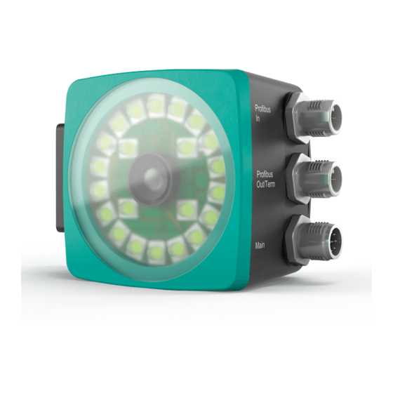
(AGV) are to be positioned precisely at marked positions along a given lane. The read head forms part of the positioning system in the Pepperl+Fuchs incident light process. The read head's features include a camera module and an integrated illumination unit. - Page 7 PGV...-F200/-F200A...-B17-V1D Product Description Tag Mode In addition to the tracking, you can use the read head in tag mode. The read head detects Data Matrix tags, which are typically glued onto the floor in a grid. The individual Data Matrix tags are numbered consecutively and include position information.
-
Page 8: Led Indicators And Controls
PGV...-F200/-F200A...-B17-V1D Product Description LED Indicators and Controls The PGV... reader is equipped with seven indicator LEDs for carrying out visual function checks and rapid diagnostics. The reader is equipped with two buttons at the back for activating parameterization mode. Button 1 is labeled ADJUST. Button 2 is labeled CONFIG. ADJUST CONFIG Figure 2.3... - Page 9 PGV...-F200/-F200A...-B17-V1D Product Description Red/ Green green/ Color Yellow Red /red Yellow Yellow Yellow yellow Description Flashes Code tape outside read range = 2 Hz flash Lights System error up red Lights Code tape detected, absolute position green available Lights Colored tape detected Colored tape outside read range...
-
Page 10: Accessories
If products are used in harsh ambient conditions, appropriate Pepperl+Fuchs accessories can be used to extend the service life of these products. -
Page 11: Installation
PGV...-F200/-F200A...-B17-V1D Installation Installation Mounting the Read Head Mount the PGV... read head on the automated guided vehicle using the four screws on the mounting adapter on the read head. Mount the read head in such a way that the lens with the ring light and camera module are directed toward the colored tape. - Page 12 PGV...-F200/-F200A...-B17-V1D Installation Read Head Dimensions M6 x 9 (4x) 13.8 12.5 Figure 3.1 Housing *-F200-* 94.5 M6 x 9 (4x) Figure 3.2 Housing *-F200A-*...
-
Page 13: Mounting The Colored Tape And Code Tape
Due to the integrated lighting of the read head, some floor colors appear to be different in the camera. If you have problems with the color selection of the colored tapes, please consult your contact at Pepperl+Fuchs. Mounting the Colored Tape 1. - Page 14 PGV...-F200/-F200A...-B17-V1D Installation Cleaning Colored Tape/Code Tape Significant contamination on the colored or code tapes can impair the detection by the read head. Clean the colored and code tapes with isopropanol if necessary. If the contamination is severe, you can use a non-corrosive plastic cleaner, e.g., Caramba®. Note! To avoid polishing the surface, do not apply strong pressure when cleaning.
- Page 15 PGV...-F200/-F200A...-B17-V1D Installation Curve radius: R ≥ 50 cm Figure 3.4 Select a curve radius that can handle the turning circle of your automated guided vehicle. The colored tape must always be located in the reading window of the read head. Angle Output Note! Angles are specified as absolute values.
- Page 16 PGV...-F200/-F200A...-B17-V1D Installation Data Matrix code tape The read head detects the absolute angle in relation to the tracked lane with a maximum resolution of 0.1°. The angle is specified absolutely relative to the tracked lane, since a Data Matrix code contains tape direction information. The output angle covers the range from 0° to 360°.
- Page 17 PGV...-F200/-F200A...-B17-V1D Installation Figure 3.7 Distance A for colored tape Data Matrix code tape The read head indicates the vertical distance of the zero point in relation to the Data Matrix code tape. Figure 3.8 Distance A for Data Matrix code tape...
- Page 18 PGV...-F200/-F200A...-B17-V1D Installation Branches The read head detects one lane at the lower edge of the field of vision and two lanes at the upper edge of the field of vision; the read head indicates this as a branch. The read head detects two lanes at the lower edge of the field of vision and one lane at the upper edge of the field of vision;...
- Page 19 PGV...-F200/-F200A...-B17-V1D Installation Colored tape Data Matrix position code Data Matrix control code Branches or intersections with position information can be displayed as follows: Figure 3.10 Separate lane branches off/converges...
- Page 20 PGV...-F200/-F200A...-B17-V1D Installation Figure 3.11 Same lane branches off/converges Note! Direction Decision The direction decision at a branch of a Data Matrix code tape remains in effect until the read head has moved more than 50 cm from the branch. It is not possible to change the direction decision within a branch! Note! Priority Data Matrix code tapes and Data Matrix tags have priority over colored tapes or colored lanes.
- Page 21 PGV...-F200/-F200A...-B17-V1D Installation Figure 3.12 Distances Behavior of the Read Head at Branches and Corners The read head behaves differently depending on the type of branch and the specified lane. The read head must know the upcoming direction decision. A second lane branches off to the left from the straight lane: The read head follows the straight lane if the direction decision "follow right-hand lane"...
- Page 22 PGV...-F200/-F200A...-B17-V1D Installation It is not permitted to create a mixture of lanes made from colored tape and Data Matrix codes at branches or intersections. Figure 3.13 Mixture of lanes with colored tape and Data Matrix codes Control codes can be mounted in the immediate vicinity of a branch with Data Matrix codes for positioning, but not near an intersection.
- Page 23 PGV...-F200/-F200A...-B17-V1D Installation Distances To ensure that the read head can clearly detect and assign colored tapes and Data Matrix codes, minimum and maximum distances must be observed when creating the lanes. Offset V between position codes of a lane must not be greater than 5 mm. Offset: 0 mm ≤...
- Page 24 PGV...-F200/-F200A...-B17-V1D Installation The distance between the Data Matrix code tapes at a branch or intersection as a separate lane must be between 0 mm and 5 mm. Distance: 0 mm ≤ D ≤ 5 mm Figure 3.17 The distance between a colored tape and a Data Matrix control code must be between 0 mm and 5 mm.
- Page 25 PGV...-F200/-F200A...-B17-V1D Installation 25 mm 25 mm 25 mm 0 mm ≤ D ≤ 5 mm Figure 3.19 A lane can switch from a colored tape to a Data Matrix code tape and back again as often as required. The distance between the colored tape and the edge of the Data Matrix code must be between 0 mm and 10 mm 0 mm ≤...
- Page 26 PGV...-F200/-F200A...-B17-V1D Installation Caution! Alignment The Data Matrix code is not on the center line of the code tape. The code tape is made of silicone-free polyester film. A position marker appears every 100 mm along the lower edge of the code tape (see "Code Tape Dimensions"). This position marker is used for various functions, including precise positioning of the code tape during installation.
- Page 27 PGV...-F200/-F200A...-B17-V1D Installation Data Matrix Code Tapes with a Starting Position of 0 m Order designation Description PGV10M-CA25-0 Code tape, length: 10 m PGV100M-CA25-0 Code tape, length: 100 m Table 3.1 See also data sheet PGV*-CA25-* at www.pepperl-fuchs.com Data Matrix control codes Order designation Description PGV-CC25-001...
-
Page 28: Electrical Connection
PGV...-F200/-F200A...-B17-V1D Installation Data Matrix Tag A Data Matrix tag contains position information in addition to a specific number. A cross in the center of the Data Matrix tag marks the zero point. The X and the Y axes are marked starting from the zero point. - Page 29 Main Figure 3.24 Color Assignment Pepperl+Fuchs female cordsets are manufactured in accordance with EN60947-5-2. When using a type V19-... single-ended female cordset with an open cable end (see chapter 2.3) on the Main connection, the following color assignment applies: Connection Pin...
-
Page 30: Profinet Connection
PGV...-F200/-F200A...-B17-V1D Installation Additional Ground Connection Using a short ground wire, add a ground to the nearest ground connection. Model number Description PCV-SC12 Clip for mounting an additional ground connection. PCV-SC12A Caution! Damage to the device Connecting an alternating current or excessive supply voltage can damage the device or cause the device to malfunction. -
Page 31: Commissioning
PGV...-F200/-F200A...-B17-V1D Commissioning Commissioning Direction Decision The read head has several ways of following colored tapes and Data Matrix code tapes depending on the parameterization. Depending on the input signal, the read head follows the right-hand, the left-hand, or the better lane. To ensure that the reader does not report any error messages after being switched on, a direction decision must be specified. - Page 32 PGV...-F200/-F200A...-B17-V1D Commissioning Following Lane with Better Quality You can parameterize the read head so that it follows the better quality color lane. Example Figure 4.2 - Better color lane - Worse color lane Following Lane with More Detailed Position Information You can parameterize the read head so that it follows the Data Matrix code tape that continues the current location information.
-
Page 33: Project Planning Using Device Description
PGV...-F200/-F200A...-B17-V1D Commissioning Project Planning Using Device Description As with PROFIBUS DP, a field device is integrated into the project planning tool by way of a device description. The field device properties are described in the GSD file. The GSD file contains the field device data (technical features and information for communication) that you need to operate the device in a PROFINET network. -
Page 34: Operation And Communication
PGV...-F200/-F200A...-B17-V1D Operation and communication Operation and communication Communication via PROFINET 5.1.1 General Information on Communication via PROFINET PROFINET is an open standard for industrial automation based on industrial Ethernet. PROFINET integrates information technology with established standards such as TCP/IP and XML in automation technology. -
Page 35: Profinet Address And Identifying A Device
PGV...-F200/-F200A...-B17-V1D Operation and communication Figure 5.1 5.1.3 Project Planning Using Device Description As with PROFIBUS DP, a field device is integrated into the project planning tool by way of a device description. The field device properties are described in the GSD file. The GSD file contains the field device data (technical features and information for communication) that you need to operate the device in a PROFINET network. -
Page 36: Profinet Modules
PGV...-F200/-F200A...-B17-V1D Operation and communication 5.1.5 PROFINET Modules 1 word = 16 bit value 1 byte = 8 bit value Modules with response telegram The following modules enable reader data to be retrieved using PROFINET. Module 1 Bit no. Content 0 ... 15 Status 16 ... - Page 37 PGV...-F200/-F200A...-B17-V1D Operation and communication Module 4 Bit no. Content 0 ... 15 Status 16 ... 47 Position Data Y 48 ... 63 Angle Data 64 ... 95 Position Data X 96 ... 127 Data Matrix Tag Number 1.see "Status" 2.see "Position Data Y" 3.see "Angle Data"...
- Page 38 PGV...-F200/-F200A...-B17-V1D Operation and communication Error Codes Error code Description Priority No clear position can be determined (difference between codes is too great, code distance incorrect, etc.) No direction decision available > 1000 Internal error Data Matrix Control Code Status Content Byte 1 Bit no.
- Page 39 PGV...-F200/-F200A...-B17-V1D Operation and communication Response Content Word 1 Bit no. Z data NCC01 NCC02 NCC03 NCC04 NCC05 NCC06 NCC07 NCC08 NCC09 NCC10 NCC11 NCC12 NCC13 NCC14 NCC15 NCC16 Position Data X Size Type Content 2 words, Input data 32-bit X data consistent MSB first Resolution: 0.1 mm, 1 mm, 10 mm, binary coded in two's complement...
- Page 40 PGV...-F200/-F200A...-B17-V1D Operation and communication Content Word 1 Word 2 Bit no. X data X data XP29 XP13 XP30 XP14 XP31 XP15 Position Data Y Size Type Content 2 words, Input data 32-bit Y data consistent MSB first Resolution: 0.1 mm, 1 mm, 10 mm, binary coded in two's complement Response Content...
- Page 41 PGV...-F200/-F200A...-B17-V1D Operation and communication Response Content Word 1 Bit no. Z data ZP01 ZP02 ZP03 ZP04 ZP05 ZP06 ZP07 ZP08 ZP09 ZP10 ZP11 ZP12 ZP13 ZP14 ZP15 ZP16 Angle Data Size Type Content 1 word, Input data 16-bit angle data consistent MSB first Resolution: 1°...
- Page 42 PGV...-F200/-F200A...-B17-V1D Operation and communication Content Word 1 Bit no. Angle Data ANG14 ANG15 ANG16 Warning Size Type Content 1 word, Input data Last warnings consistent Last warning no. Response Content Word 1 Bit no. Last warning data WRN01 WRN02 WRN03 WRN04 WRN05 WRN06...
- Page 43 PGV...-F200/-F200A...-B17-V1D Operation and communication Content Bit no. Word 1 Description WRN09 Temperature too high WRN10 Reserved WRN11 Reserved WRN12 Reserved WRN13 Reserved WRN14 Reserved WRN15 Reserved WRN16 Reserved Table 5.1 If no warnings are present, all bits in the warning data set are set to 0. Modules with Input Data The modules below can be used to send data to the reader via PROFINET.
- Page 44 PGV...-F200/-F200A...-B17-V1D Operation and communication Global Primary Data The global primary data allows you to parameterize the reader using PROFINET. Global primary data is always transferred to the reader in full. Sub- Parameter index Designation Function data Data type Primary data Number of unsigned8 Subsequent...
-
Page 45: Operation Using Control Codes
PGV...-F200/-F200A...-B17-V1D Operation and communication Operation Using Control Codes In numerous positioning system applications, defined processes (= event) must be started at specific positions. This means that the exact positions must be defined via code tapes for positioning, instead of simple colored tapes. In the context of lane tracking, it is advisable to mark branches using control codes to facilitate the control of the direction decision. -
Page 46: Operation Using Repair Tape
PGV...-F200/-F200A...-B17-V1D Operation and communication Operation Using Repair Tape The repair tape is a short code tape one meter in length. The repair tape is used to bridge defective or damaged areas of an existing code tape. 1. Cut the repair tape to the required length 2. -
Page 47: Appendix
PGV...-F200/-F200A...-B17-V1D Appendix Appendix ASCII table ASCII ASCII ASCII hex ASCII Space " & < >... - Page 48 Twinsburg, Ohio 44087 · USA Tel. +1 330 4253555 E-mail: sales@us.pepperl-fuchs.com Asia Pacific Headquarters Pepperl+Fuchs Pte Ltd. Company Registration No. 199003130E Singapore 139942 Tel. +65 67799091 E-mail: sales@sg.pepperl-fuchs.com www.pepperl-fuchs.com Subject to modifications / DOCT-5883 Copyright PEPPERL+FUCHS • Printed in Germany 11/2017...
Need help?
Do you have a question about the PGV Series and is the answer not in the manual?
Questions and answers