Table of Contents
Advertisement
Quick Links
Advertisement
Table of Contents

Related Manuals for Pepperl+Fuchs PGV100R-F200-R4-1.5M


Summary of Contents for Pepperl+Fuchs PGV100R-F200-R4-1.5M
- Page 1 PGV100R-F200-R4-1.5M Incident Light Positioning System Manual...
- Page 2 Phone: +49 621 776 - 0 E-mail: info@de.pepperl-fuchs.com North American Headquarters Pepperl+Fuchs Inc. 1600 Enterprise Parkway Twinsburg, Ohio 44087 Phone: +1 330 425-3555 E-mail: sales@us.pepperl-fuchs.com Asia Headquarters Pepperl+Fuchs Pte. Ltd. P+F Building 18 Ayer Rajah Crescent Singapore 139942 Phone: +65 6779-9091 E-mail: sales@sg.pepperl-fuchs.com https://www.pepperl-fuchs.com...
-
Page 3: Table Of Contents
PGV100R-F200-R4-1.5M Contents Introduction........................ 5 Content of this Document ................5 Target Group, Personnel ................5 Symbols Used ....................6 Product Description ....................7 Use and Application ..................7 RS-485 Interface .................... 9 LED Indicators and Operating Elements ............. 9 Accessories....................11 Installation........................ - Page 4 PGV100R-F200-R4-1.5M Contents Code Cards for External Parameterization..........36 6.1.1 Code Cards with Special Functions..........36 6.1.2 Code Cards for Setting the Read Head Address ......39 6.1.3 Code cards for setting the transfer rate ..........41 6.1.4 Code Cards for Adjusting the Resolution.......... 43 6.1.5...
-
Page 5: Introduction
PGV100R-F200-R4-1.5M Introduction Introduction Content of this Document This document contains information required to use the product in the relevant phases of the product life cycle. This may include information on the following: • Product identification • Delivery, transport, and storage •... -
Page 6: Symbols Used
PGV100R-F200-R4-1.5M Introduction Symbols Used This document contains symbols for the identification of warning messages and of informative messages. Warning Messages You will find warning messages, whenever dangers may arise from your actions. It is mandatory that you observe these warning messages for your personal safety and in order to avoid prop- erty damage. -
Page 7: Product Description
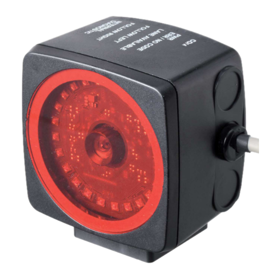
The read head forms part of the positioning system in the Pepperl+Fuchs incident light pro- cess. The read head includes a camera module and an internal illumination unit, which the read head uses to detect a strip of Data Matrix code tape stuck to the floor for lane tracking and nav- igation. - Page 8 PGV100R-F200-R4-1.5M Product Description Tag Mode In addition to lane tracking, the read head can also be used in tag mode. The read head detects Data Matrix tags, which are typically glued onto the floor in a grid. The individual Data Matrix tags are numbered consecutively and include position information.
-
Page 9: Rs-485 Interface
PGV100R-F200-R4-1.5M Product Description RS-485 Interface The read head is equipped with an RS-485 interface for communication purposes, i.e. parame- terizing the read head functions or reading out current process data during operation. This interface is operated in 8-E-1 operating mode and is fitted with a terminator that can be acti- vated or deactivated by parameterizing the sensor head. - Page 10 PGV100R-F200-R4-1.5M Product Description LED fault indicator NO CODE/ Mode COM STATE COM ERROR POWER ON ERROR Color Green Yellow Green Description No communication Flashing Communication active Lights up once Warning limit reached State Lights up twice "Control Event" error Lights up three times x...
-
Page 11: Accessories
If products are used in harsh ambient conditions, appropriate Pepperl+Fuchs accessories can be used to extend the service life of these products. -
Page 12: Installation
PGV100R-F200-R4-1.5M Installation Installation Mounting the Read Head Mount the read head on the auto-guided transport system using the four screws on the mount- ing adapter on the read head. Mount the read head so that the lens with ring light and camera module are aligned toward the floor. -
Page 13: Affixing The Code Tape
PGV100R-F200-R4-1.5M Installation Affixing the Code Tape Dimensions of the Code Tape Figure 3.2 Dimensions of the Data Matrix code tape Caution! Alignment The Data Matrix code is not on the center line of the code tape. Caution! Stop edges If you attach another code tape at the end of a previous code tape, the code pattern of 20 mm must be retained. - Page 14 PGV100R-F200-R4-1.5M Installation Data Matrix Control Codes Model number Description PGV-CC25-001 Code tape, Control Code 001, length: 1 m PGV-CC25-999 Code tape, Control Code 999, length: 1 m Table 3.2 Data Matrix control codes Affixing the Code Tape Clean the surface of any greasy or oily deposits and dust.
- Page 15 PGV100R-F200-R4-1.5M Installation Cleaning the Code Tape Significant contamination on code tapes can impair detection by the read head. Clean the code tapes with isopropanol if necessary. If the contamination is severe, you can use a non-corrosive plastic cleaner, e.g., Caramba®.
- Page 16 PGV100R-F200-R4-1.5M Installation Distance Output The read head detects the distance from the zero point in the Y direction a Data Matrix code tape and transmits this value to the control panel. The reader indicates the vertical distance of the zero point in relation to the Data Matrix code tape.
- Page 17 PGV100R-F200-R4-1.5M Installation Figure 3.6 Distances Behavior of the Read Head at Branches and Curves The read head behaves differently depending on the type of branch and the specified lane. The read head must know the upcoming direction decision. A second lane branches off to the left from the straight lane: The read head follows the straight lane if the direction decision "follow right-hand lane"...
- Page 18 PGV100R-F200-R4-1.5M Installation Control codes can be mounted in the immediate vicinity of a branch with Data Matrix codes for positioning, but not near an intersection. The control code must be mounted directly next to the guiding lane. Figure 3.7 Branch with control code...
- Page 19 PGV100R-F200-R4-1.5M Installation The distance between the Data Matrix code tapes at a branch or intersection as a separate lane must be between 0 mm and 5 mm. Figure 3.9 Distance: 0 mm D 5 mm The distance between a Data Matrix position code and a Data Matrix control code must be between 0 mm and 5 mm.
- Page 20 PGV100R-F200-R4-1.5M Installation Data Matrix Tag (8 digit number) A Data Matrix tag contains position information and a specific 8 digit number. A cross in the center of the Data Matrix tag marks the zero point. The X and the Y axes are marked starting from the zero point.
- Page 21 PGV100R-F200-R4-1.5M Installation Data Matrix Tag — Extended (14 digit number) A Data Matrix tag contains position information and a specific 14 digit number. A cross in the center of the Data Matrix tag marks the zero point. The X and the Y axes are marked starting from the zero point.
-
Page 22: Electrical Connection
PGV100R-F200-R4-1.5M Installation Electrical Connection The read head is connected electrically via a fixed cable with open cores on the side of the housing. The power is supplied via this connection. The configurable inputs and outputs on the read head are also located at this connection. - Page 23 PGV100R-F200-R4-1.5M Installation Caution! Damage to the device Connecting an alternating current or excessive supply voltage can damage the device or cause the device to malfunction. Electrical connections with reversed polarity can damage the device or cause the device to malfunction.
-
Page 24: Commissioning
PGV100R-F200-R4-1.5M Commissioning Commissioning Direction Decision The read head has several ways of following Data Matrix code tapes depending on the param- eterization. Depending on the input signal, the read head follows the right-hand lane, the left- hand lane, or the better lane. -
Page 25: Parameterization Using Code Cards
PGV100R-F200-R4-1.5M Commissioning Parameterization Using Code Cards During parameterization, the read head scans special code cards optically and configures the relevant parameters. Simply hold the corresponding code cards at the correct distance in front of the lens on the read head. The standard code cards are in the appendix. -
Page 26: The Code Cards "Cancel", "Use", And "Default
PGV100R-F200-R4-1.5M Commissioning 4.2.1 The code cards "CANCEL", "USE", and "DEFAULT" Holding one of these cards in front of the reading head exits parameterization mode with the following consequences: • CANCEL: All parameter changes that are made but have not yet been saved are discarded. The reading head operates with the last valid parameters that were saved. -
Page 27: Operation And Communication
PGV100R-F200-R4-1.5M Operation and communication Operation and communication Communication via the RS-485 Interface The controller and read head communicate via the RS-485 interface during operation. Make sure that the basic communication settings have been made on the read head, such as setting the read head address and baud rate. -
Page 28: Position Response Telegram
PGV100R-F200-R4-1.5M Operation and communication 5.1.2 Position Response Telegram A response telegram is 21 bytes long. Bytes 1 and 2 contain the read head address and status information. Response telegram from the read head — lane tracking Bit 8 Bit 7 Bit 6... - Page 29 PGV100R-F200-R4-1.5M Operation and communication Response telegram from the read head — Data Matrix tag Bit 8 Bit 7 Bit 6 Bit 5 Bit 4 Bit 3 Bit 2 Bit 1 Bit 0 Byte 1 Parity Byte 2 Parity TAG [1]...
- Page 30 X position of right lane Y position of left lane Y position of right lane Table 5.5 Functional description of the bits 1. Should you have any questions, please contact Pepperl+Fuchs Error Codes Error code Description Priority No clear position can be determined, e.g., difference between codes is too great, code distance incorrect No direction decision available, , see chapter 5.1.3...
-
Page 31: Number Of Lanes Lc (Lane Count)
1. Unsigned: Fill in the missing upper bits with "0". 2. Signed: Fill in the missing upper bits with the highest bit of the response telegram. Should you have any questions about this, please contact Pepperl+Fuchs. 5.1.2.1 Number of Lanes LC (Lane Count) The lane count, LC, indicates the number of found Data Matrix lanes in the reading window. -
Page 32: Orientation O
PGV100R-F200-R4-1.5M Operation and communication 5.1.2.2 Orientation O The orientation O indicates the orientation of the control codes in the reading window. Meaning of Bits Meaning Control code has the same orientation as ascending Data Matrix lane Orientation of control code rotated 90° clockwise in relation to ascending Data Matrix lane Orientation of control code rotated 180°... -
Page 33: Side S
PGV100R-F200-R4-1.5M Operation and communication 5.1.2.3 Side S Side S specifies the side of the Data Matrix lane on which the control codes are present. Meaning of Bits Meaning No control code is present or found Reserved Control code to the right of the Data Matrix lane... -
Page 34: Operation Using Control Codes
PGV100R-F200-R4-1.5M Operation and communication Meaning of Bits Meaning Error code 5 Follow right-hand lane Follow left-hand lane Straight ahead Table 5.10 Example Request telegram when read head address = 0 Request Response Description Example 0xE8, 0x17 See "Response Tele- Follow left-hand lane --"0x02"--... -
Page 35: Operation Using Repair Tape
PGV100R-F200-R4-1.5M Operation and communication Control codes are identified by the printed number, in this case "Control 12". Figure 5.2 PGV-CC25-0012 The illustration shows part of control code #12 Refer to the "Accessories" chapter for ordering information relating to control codes. -
Page 36: Appendix
PGV100R-F200-R4-1.5M Appendix Appendix Code Cards for External Parameterization Here you will find the code cards that enable you to parameterize some of the basic functions of the read head in a step-by-step process. For the exact external parameterization procedure see chapter 4.2. - Page 37 PGV100R-F200-R4-1.5M Appendix User User Figure 6.2 The "USER" code card is used to activate the user level in the external parameterization operating mode. Store Figure 6.3 The "STORE" code card stores the modified parameterization in the nonvolatile memory of the read head and terminates external parameterization operating mode.
- Page 38 PGV100R-F200-R4-1.5M Appendix Figure 6.5 The "USE" code card takes over the set configuration volatile in the read head working memory and terminates the external parameterization operating mode. The read head then operates with this configuration. However, if the read head is switched off and on again, the configuration is lost and the read head operates with the last valid configuration that was saved.
-
Page 39: Code Cards For Setting The Read Head Address
PGV100R-F200-R4-1.5M Appendix 6.1.2 Code Cards for Setting the Read Head Address A unique address must be assigned to the read head so that it can be activated via the inter- face. The address range extends from 0 ... 3. Read Head Address 0 Adresse 0 Figure 6.7... - Page 40 PGV100R-F200-R4-1.5M Appendix Read Head Address 3 Adresse 3 Figure 6.10 The code card assigns address 3 to the read head.
-
Page 41: Code Cards For Setting The Transfer Rate
PGV100R-F200-R4-1.5M Appendix 6.1.3 Code cards for setting the transfer rate Parameterization allows you to assign various transfer rates to the reading head for communi- cation via the interface. The following transfer rates are available: • 38400 bit/s • 57600 bit/s •... - Page 42 PGV100R-F200-R4-1.5M Appendix Transfer rate: 76800 bit/s 76800 Bit/s Figure 6.13 The transfer rate of the read head for communication via the interface is preset to 76800 bit/s. Transfer rate: 115200 bit/s 115200 Bit/s Figure 6.14 The transfer rate of the read head for communication via the interface is preset to 115200 bit/s.
-
Page 43: Code Cards For Adjusting The Resolution
PGV100R-F200-R4-1.5M Appendix 6.1.4 Code Cards for Adjusting the Resolution Parameterization enables you to assign a position data resolution of 0.1 mm / 1 mm / 10 mm to the read head. Resolution: 0.1 mm Resolution 0.1 mm Figure 6.16 The code card assigns a position data resolution of 0.1 mm to the read head. -
Page 44: Code Cards For Adjusting The Terminator
PGV100R-F200-R4-1.5M Appendix Maximum Length of the Code Tape Resolution of the read head [mm] Maximum length of the code tape [km] 6.1.5 Code cards for adjusting the terminator Parameterization enables you to switch a terminator on and off in the read head:... - Page 45 Pepperl+Fuchs Quality Download our latest policy here: www.pepperl-fuchs.com/quality www.pepperl-fuchs.com © Pepperl+Fuchs · Subject to modifications Printed in Germany / DOCT-6492...
Need help?
Do you have a question about the PGV100R-F200-R4-1.5M and is the answer not in the manual?
Questions and answers