
Subscribe to Our Youtube Channel
Related Manuals for Pepperl+Fuchs VisuNet TCU1100 Series


Summary of Contents for Pepperl+Fuchs VisuNet TCU1100 Series
- Page 1 PROCESS AUTOMATION MANUAL VisuNet Computing Unit TCU1100-*/TCU1200-* PCU1100-*/PCU1200-*...
- Page 2 VisuNet Computing Unit With regard to the supply of products, the current issue of the following document is ap- plicable: The General Terms of Delivery for Products and Services of the Electrical Indus- try, published by the Central Association of the Electrical Industry (Zentralverband Elektrotechnik und Elektroindustrie (ZVEI) e.V.) in its most recent version as well as the supplementary clause: "Expanded reservation of proprietorship"...
-
Page 3: Table Of Contents
VisuNet Computing Unit Introduction................. 4 Content of this Document ..............4 Target Group, Personnel..............4 Symbols Used ..................5 Product Description ..............6 Overview ....................6 Technical Specifications..............9 Dimensions and Type Labels............12 Scope of Delivery................13 Disposal ....................13 Installation................. -
Page 4: Introduction
VisuNet Computing Unit Introduction Introduction Content of this Document This document contains information that you need in order to use your product throughout the applicable stages of the product life cycle. These can include the following: Product identification ■ Delivery, transport, and storage ■... -
Page 5: Symbols Used
VisuNet Computing Unit Introduction Symbols Used This document contains symbols for the identification of warning messages and of informative messages. Warning Messages You will find warning messages, whenever dangers may arise from your actions. It is mandatory that you observe these warning messages for your personal safety and in order to avoid property damage. -
Page 6: Product Description
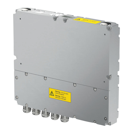
Zones 1/21 and 2/22 and Class I/II, Div. 2 and Class III. Connected to Pepperl+Fuchs display units, the TCU and PCU devices serve as thin-client- or PC-based computing units. The TCU devices run VisuNet RM Shell firmware and allow users to easily connect to a host system via Ethernet. - Page 7 VisuNet Computing Unit Product Description Component Overview Description Tightening Torque Terminal compartment cover Breather vent 10 mounting holes Terminal compartment Optional cable glands Standard cable glands for 5 Nm power supply, USB Ex e, Ethernet, 2 x USB Ex i 12 x mounting screws for 1.5 Nm terminal compartment cover...
- Page 8 VisuNet Computing Unit Product Description Danger! Accumulation of condensed water within the housing can cause a short and result in an ignition. A blocked breather vent cannot provide ventilation or drainage. Do not block or restrict the breather vent! Do not insert any sharp objects into the breather vent! Cable Gland Connection Layout The cable glands have different inlays in different sizes.
-
Page 9: Technical Specifications
Pepperl+Fuchs interface v1.0 for display units 1 x Ethernet 100/1000BASE-TX (Ex e) or fiber optic 1000Base-SX 1 x USB 2.0 (Ex e) 2 x USB 1.1 (Ex i; intended for Pepperl+Fuchs keyboard and mouse) optional: 1 x barcode reader interface Pepperl+Fuchs Pscan-D/B (Ex i) - Page 10 Pepperl+Fuchs interface v1.0 for display units 1 x Ethernet 100/1000BASE-TX (Ex e) or fiber optic 1000Base-SX 1 x USB 2.0 (Ex e) 2 x USB 1.1 (Ex i; intended for Pepperl+Fuchs keyboard and mouse) optional: 1 x barcode reader interface Pepperl+Fuchs Pscan-D/B (Ex i)
- Page 11 280 mm x 240 mm x 43 mm ATEX/IECEx Marking Thin Client Unit TCU1100-J1-* PC Unit PCU1100-J1-* Pepperl+Fuchs GmbH Lilienthalstraße 200, 68307 Mannheim, Germany ATEX: II 2G Ex eb q ib IIC T4 IP66 Gb II 2D Ex tb IIIC T80 °C Db IECEx: IECEx BVS 16.0061X...
-
Page 12: Dimensions And Type Labels
VisuNet Computing Unit Product Description Dimensions and Type Labels Dimensions 44.8... -
Page 13: Scope Of Delivery
VisuNet Computing Unit Product Description Labels The following labels are present on the TCU/PCU. Warning marking "Warning – Do not open! This container has Warning - Do not open! been permanently sealed and cannot be repaired." This container has been "Avertissement –... -
Page 14: Installation
VisuNet Computing Unit Installation Installation General Installation Requirements The equipment must be installed by competent personnel in accordance with the ■ instructions. National laws and regulations must be observed. The building installation must provide a 20 A overcurrent protection. ■ The installer must make a readily accessible disconnect device available. - Page 15 VisuNet Computing Unit Installation Terminal Compartment Ex e X1: Power Supply +24 V DC / USB Ex e Terminal X1.1 Power Supply X1.2 X1.3 X1.4 X1.5 USB Ex e X1.6 X1.7 X1.8 The table below gives an overview of the 2 color schemes: The Ethernet terminal assignment can be done either by EIA/TIA-568A or by EIA/TIA-568B color scheme.
- Page 16 VisuNet Computing Unit Installation Optional Fiber-Optic Interface Note! When the fiber-optic interface is installed, no terminal connections are available at X2. Fiber Optic Specifications Minimum cable requirement OM2 (50/125 µm) Data rate 1 Gb Max. distance 550 m Mode Multimode Category 1000-BASE-SX Link budget...
- Page 17 VisuNet Computing Unit Installation Terminal Compartment Ex i X3: USB for Keyboard and Mouse EXTA2 Ex i Peripheral Terminal Signal Assignment Color coding Name Direction X3.1 Supply 1st USB Ex i VCC (Ui) green (Keyboard) gray X3.2 brown X3.3 X3.4 Supply yellow X3.5...
- Page 18 VisuNet Computing Unit Installation DATL-PSCAN-D-XX00-N0 Power Cable for PSCAN-* yellow (Us) brown/gray (GND) green (RxD) white (TxD) X4 or X5: "S3" Scanner Option for Handheld Reader IDM160* and Base Station IDMx61- B-N0* Ex i Cable Terminal Signal Name Direction Assignment Color coding Pin M12 connector...
- Page 19 VisuNet Computing Unit Installation X4 or X5: 100/1000BASE-TX Option "ET" Ex e Ethernet Terminal Ethernet Terminal Assignment acc. Assignment acc. Terminal EIA/TIA-568B EIA/TIA-568A Xx.1 Tx+/D1+ white / orange white / green line line OR fully green Xx.2 Tx-/D1- orange / white green / white line line OR fully orange Xx.3...
- Page 20 VisuNet Computing Unit Installation X4 or X5: RS-485 Option "S2" Ex e Terminal Signal Name Direction Xx.1 120A Termination Xx.2 Xx.3 120Z Termination Xx.4 Xx.5 Xx.6 Xx.7 Xx.8 HD/FD (Control function)
- Page 21 VisuNet Computing Unit Installation RS-485 Cabling Possible network connections include the following: Full duplex ■ Terminated (120 Ohm) full duplex ■ Half duplex ■ Terminated half duplex ■ Figure 3.2 Full duplex cabling Figure 3.3 Half duplex cabling RS-485 Specifications Cable Shielded 0.75 mm (e.g., LiYCY 4 x 0.75)
-
Page 22: Mechanical Installation
Mounting the TCU/PCU onto the Display Unit 1. Ensure the correct position of the TCU/PCU. 2. Place the TCU/PCU with the Pepperl+Fuchs connector above the Pepperl+Fuchs socket on the back of the display unit. 3. Carefully push the Pepperl+Fuchs connector into the Pepperl+Fuchs socket. -
Page 23: Bios Settings
VisuNet Computing Unit BIOS Settings BIOS Settings The default BIOS password is hmiadmin1234. It is recommended to change the password in order to prevent unauthorized access to the system BIOS. The password is needed at all times to access the BIOS and/or change any BIOS settings. The device is shipped with optimized BIOS settings and it is highly recommended not to change the BIOS settings. -
Page 24: Factory Reset
VisuNet Computing Unit Factory Reset Factory Reset VisuNet PCUs and TCUs can be reset to their original factory configurations. TCUs that use VisuNet RM Shell firmware can be reset via functions that are available in RM Shell. Refer to RM Shell documentation for instructions on performing a factory reset. PCUs that use a pre-installed Windows 7 Ultimate or Windows 10 IoT Enterprise operating... -
Page 25: Appendix
Appendix System Health Monitoring When using the thin client unit in combination with the Pepperl+Fuchs display units DPU1100 / DPU1200-* there is a health monitoring for possible hardware errors that helps you to indicate what is wrong with the hardware components. - Page 26 VisuNet Computing Unit Appendix Temperature Error (too High) Indication Problem Solution "Brightness +" button solid Temperature too high Check if ambient temperature white (monitored only during surrounding the panel Power button solid red booting up) exceeds the panel's allowed operating temperature. Communication Error Indication Problem...
-
Page 27: Ul Control Drawing
VisuNet Computing Unit Appendix UL Control Drawing Connections Hazardous Location Hazardous Location Class I, Division 2, Groups A, B, C, D; T4 Class I, Division 2, Groups A, B, C, D; T4 Class II, Division 2, Groups F, G; T4 Class II, Division 2, Groups F, G;... - Page 28 PROCESS AUTOMATION – PROTECTING YOUR PROCESS Worldwide Headquarters Pepperl+Fuchs GmbH 68307 Mannheim · Germany Tel. +49 621 776-0 E-mail: info@de.pepperl-fuchs.com For the Pepperl+Fuchs representative closest to you check www.pepperl-fuchs.com/contact www.pepperl-fuchs.com Subject to modifications / DOCT-5302E Copyright PEPPERL+FUCHS • Printed in Germany 11/2018...
Need help?
Do you have a question about the VisuNet TCU1100 Series and is the answer not in the manual?
Questions and answers