
Related Manuals for Pepperl+Fuchs PGV F200


Summary of Contents for Pepperl+Fuchs PGV F200
- Page 1 FACTORY AUTOMATION MANUAL PGV...-F200/-F200A...-B16-V15 Incident Light Positioning System...
- Page 2 PGV...-F200/-F200A...-B16-V15 With regard to the supply of products, the current issue of the following document is ap- plicable: The General Terms of Delivery for Products and Services of the Electrical Indus- try, published by the Central Association of the Electrical Industry (Zentralverband Elektrotechnik und Elektroindustrie (ZVEI) e.V.) in its most recent version as well as the supplementary clause: "Expanded reservation of proprietorship"...
-
Page 3: Table Of Contents
PGV...-F200/-F200A...-B16-V15 Safety ................... 5 Introduction ..................5 1.1.1 Contents .................... 5 1.1.2 Target Group, Personnel ..............5 1.1.3 Symbols Used..................5 Product Description ..............7 Use and Application................7 LED Indicators and Controls............... 8 Accessories ..................12 Installation................. 13 Mounting the Read Head ..............13 Mounting the Colored Tape and Code Tape ........ - Page 4 PGV...-F200/-F200A...-B16-V15 Appendix ................... 67 ASCII table...................67 Code cards with special functions ...........67 Code Cards for Setting the Baud Rate ..........69...
-
Page 5: Safety
PGV...-F200/-F200A...-B16-V15 Safety Safety Introduction 1.1.1 Contents This document contains information that you need in order to use your product throughout the applicable stages of the product life cycle. These can include the following: Product identification Delivery, transport, and storage Mounting and installation Commissioning and operation Maintenance and repair Troubleshooting... - Page 6 PGV...-F200/-F200A...-B16-V15 Safety Warning Messages You will find warning messages, whenever dangers may arise from your actions. It is mandatory that you observe these warning messages for your personal safety and in order to avoid property damage. Depending on the risk level, the warning messages are displayed in descending order as follows: Danger! This symbol indicates an imminent danger.
-
Page 7: Product Description
(AGV) are to be positioned precisely at marked positions along a given lane. The read head forms part of the positioning system in the Pepperl+Fuchs incident light process. The read head's features include a camera module and an integrated illumination unit. -
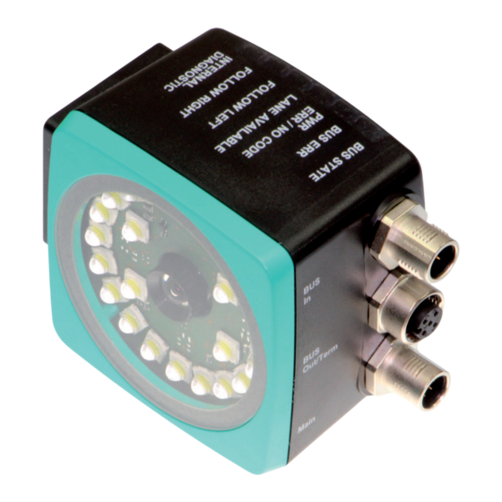
Page 8: Led Indicators And Controls
PGV...-F200/-F200A...-B16-V15 Product Description Tag Mode In addition to the tracking, you can use the read head in tag mode. The read head detects Data Matrix tags, which are typically glued onto the floor in a grid. The individual Data Matrix tags are numbered consecutively and include position information. - Page 9 PGV...-F200/-F200A...-B16-V15 Product Description ADJUST CONFIG Figure 2.3...
- Page 10 PGV...-F200/-F200A...-B16-V15 Product Description Red/ Green/ green/ Color Yellow Yellow Yellow Yellow yellow Description Flashes Code tape outside read range = 2 Hz flash Lights up System error Lights up Code tape detected, absolute green position available Lights Colored tape detected Colored tape outside read range No direction selection activated...
- Page 11 PGV...-F200/-F200A...-B16-V15 Product Description CANopen Function Indicator Red/ Green/ green/ Color Yellow Yellow Yellow Yellow yellow Description Flickers Flickers Detection of auto baud rate = 10 Hz flicker Flashes "Preoperational" mode = 2.5 Hz flash Flashes Stopped once 1 x on briefly, 1 sec off Lights up "Operational"...
-
Page 12: Accessories
If products are used in harsh ambient conditions, appropriate Pepperl+Fuchs accessories can be used to extend the service life of these products. -
Page 13: Installation
PGV...-F200/-F200A...-B16-V15 Installation Installation Mounting the Read Head Mount the PGV... read head on the automated guided vehicle using the four screws on the mounting adapter on the read head. Mount the read head in such a way that the lens with the ring light and camera module are directed toward the colored tape. - Page 14 PGV...-F200/-F200A...-B16-V15 Installation Read Head Dimensions M6 x 9 (4x) 13.8 12.5 Figure 3.1 Housing *-F200-* 94.5 M6 x 9 (4x) Figure 3.2 Housing *-F200A-* Caution! When selecting the length of the mounting screws, ensure that the maximum insertion depth of the screws in the threaded inserts on the read head is 8 mm.
-
Page 15: Mounting The Colored Tape And Code Tape
Due to the integrated lighting of the read head, some floor colors appear to be different in the camera. If you have problems with the color selection of the colored tapes, please consult your contact at Pepperl+Fuchs. Mounting the Colored Tape 1. - Page 16 PGV...-F200/-F200A...-B16-V15 Installation Cleaning Colored Tape/Code Tape Significant contamination on the colored or code tapes can impair the detection by the read head. Clean the colored and code tapes with isopropanol if necessary. If the contamination is severe, you can use a non-corrosive plastic cleaner, e.g., Caramba®. Note! To avoid polishing the surface, do not apply strong pressure when cleaning.
- Page 17 PGV...-F200/-F200A...-B16-V15 Installation The read head detects a change of the angle of the colored tape and the Data Matrix code tape and outputs this value to the controller. The output value is different for colored tapes and Data Matrix code tapes. Colored tape The read head detects the angle in relation to the tracked lane with a resolution of 360 (corresponds to 1°).
- Page 18 PGV...-F200/-F200A...-B16-V15 Installation Distance Output The read head detects the distance from the zero point in the Y direction of a colored tape or a Data Matrix code tape and outputs this value to the controller. The output value is different for colored tapes and Data Matrix code tapes due to the lack of an X position for colored tapes.
- Page 19 PGV...-F200/-F200A...-B16-V15 Installation Branches The read head detects one lane at the lower edge of the field of vision and two lanes at the upper edge of the field of vision; the read head indicates this as a branch. The read head detects two lanes at the lower edge of the field of vision and one lane at the upper edge of the field of vision;...
- Page 20 PGV...-F200/-F200A...-B16-V15 Installation Colored tape Data Matrix position code Data Matrix control code Branches or intersections with position information can be displayed as follows: Figure 3.10 Separate lane branches off/converges...
- Page 21 PGV...-F200/-F200A...-B16-V15 Installation Figure 3.11 Same lane branches off/converges Note! Direction Decision The direction decision at a branch of a Data Matrix code tape remains in effect until the read head has moved more than 50 cm from the branch. It is not possible to change the direction decision within a branch! Note! Priority Data Matrix code tapes and Data Matrix tags have priority over colored tapes or colored lanes.
- Page 22 PGV...-F200/-F200A...-B16-V15 Installation Figure 3.12 Distances Behavior of the Read Head at Branches and Corners The read head behaves differently depending on the type of branch and the specified lane. The read head must know the upcoming direction decision. A second lane branches off to the left from the straight lane: The read head follows the straight lane if the direction decision "follow right-hand lane"...
- Page 23 PGV...-F200/-F200A...-B16-V15 Installation Figure 3.13 Mixture of lanes with colored tape and Data Matrix codes Control codes can be mounted in the immediate vicinity of a branch with Data Matrix codes for positioning, but not near an intersection. The control code must be mounted directly next to the guiding lane.
- Page 24 PGV...-F200/-F200A...-B16-V15 Installation Figure 3.15 Offset: 0 mm ≤ V ≤ 5 mm The distance D between the colored tapes at a branch or intersection as a separate lane must not exceed 15 mm. The distance decreases if the guiding colored tape cannot be detected by the read head in the center of the reading window.
- Page 25 PGV...-F200/-F200A...-B16-V15 Installation Figure 3.17 Distance: 0 mm ≤ D ≤ 5 mm The distance between a colored tape and a Data Matrix control code must be between 0 mm and 5 mm. 25 mm 10...40 mm 25 mm Figure 3.18 0 mm ≤...
- Page 26 PGV...-F200/-F200A...-B16-V15 Installation 25 mm 25 mm 25 mm Figure 3.19 0 mm ≤ D ≤ 5 mm A lane can switch from a colored tape to a Data Matrix code tape and back again as often as required. The distance between the colored tape and the edge of the Data Matrix code must be between 0 mm and 10 mm Figure 3.20 0 mm ≤...
- Page 27 PGV...-F200/-F200A...-B16-V15 Installation Installing the Code Tape 1. Clean the surface of any greasy or oily deposits and dust. 2. Ensure that the surface is dry, clean, and stable. 3. Pull away a few centimeters of the protective film at the beginning of the code tape. Place the code tape at the precise point of the required starting position on the surface, and press to attach.
- Page 28 PGV...-F200/-F200A...-B16-V15 Installation Caution! Stop edges If you attach another code tape at the end of a previous code tape, the code pattern of 20 mm must be retained. Note! Bends If mounting the code tape in corners, cut the code tape several times as illustrated. Bend to the left Bend to the right Data Matrix Tag...
-
Page 29: Electrical Connection
Main Figure 3.24 Color Assignment Pepperl+Fuchs single-ended cordsets (female) are manufactured in accordance with EN60947-5-2. When using a type V19-... () female cordset with an open cable end on the Main connection, the colors are assigned as follows: Connection pin... -
Page 30: Canopen Connection
PGV...-F200/-F200A...-B16-V15 Installation In exceptional cases, the shielding of a connection at one end may be more favorable if An equipotential bonding cable is not laid or cannot be laid. A film shield is used. The following points relating to shielding must also be noted: Use metal cable clips that cover large areas of the shield. -
Page 31: Commissioning
PGV...-F200/-F200A...-B16-V15 Commissioning Commissioning Specifying the First Direction Decision To ensure that the read head does not report any error messages after being switched on, a direction decision must be specified. You can control the direction decision via the INPUT_SELECTION_DIR_RIGHT and INPUT_SELECTION_DIR_LEFT inputs. . Direction decision Error 5 Left... - Page 32 PGV...-F200/-F200A...-B16-V15 Commissioning Following Lane with Better Quality You can parameterize the read head so that it follows the better quality color lane. Example Figure 4.2 - Better color lane - Worse color lane Following Lane with More Detailed Position Information You can parameterize the read head so that it follows the Data Matrix code tape that continues the current location information.
-
Page 33: Parameterization Of Fieldbus Address And Baud Rate
PGV...-F200/-F200A...-B16-V15 Commissioning Parameterization of Fieldbus Address and Baud Rate Before the reader can communicate with the CANopen fieldbus, the fieldbus address and baud rate parameters must be set. Parameterization Using Code Cards During external parameterization, the reader scans the special code cards optically and configures the relevant parameters. -
Page 34: Product Documentation On The Internet
PGV...-F200/-F200A...-B16-V15 Commissioning Activating Parameterization Mode 1. Press button 2 on the rear of the reader and hold for longer than 2 seconds. Yellow LED3 now flashes. 2. Hold the "ENABLE" code in front of the camera system on the reader to trigger final activation If the "ENABLE"... -
Page 35: Eds Configuration File
PGV...-F200/-F200A...-B16-V15 Commissioning EDS Configuration File To assist with the configuration, you can download the EDS file from the download area of our Internet homepage http://www.pepperl-fuchs.com. Simply enter the product name or item number in the Product/Keyword search box and click Search. Select your product from the list of search results. -
Page 36: Operation And Communication
PGV...-F200/-F200A...-B16-V15 Operation and communication Operation and communication Data Exchange in the CANopen Bus 5.1.1 General Information about CANopen CANopen is a multimaster-compliant fieldbus system based on the CAN (Controller Area Network). Figure 5.1 Devices on the CANopen fieldbus communicate via message identifiers rather than via addresses. -
Page 37: Basic Technical Information About Canopen
PGV...-F200/-F200A...-B16-V15 Operation and communication Process data objects (PDOs) Service data objects (SDOs) Are used for real-time data exchange Permit access to the object directory; each SDO assembles a point-to-point service communication channel. Typically messages with high priority Messages with lower priority Synchronous and asynchronous data transfer Typically asynchronous data transfer Cyclical and noncyclical transmission Typically noncyclical transmission... - Page 38 PGV...-F200/-F200A...-B16-V15 Operation and communication Shielding Ensure continuous shielding when cabling the reader. For details of the suitable fieldbus cables, see chapter 2.3. Startup Behavior After switch-on, the reader in a CANopen network passes through several operating states. 1. Initialization Startup process of the reader. 2.
- Page 39 PGV...-F200/-F200A...-B16-V15 Operation and communication "Transmission Type" parameter Transmission Description Event-controlled Reader sends data when "Operational" state is Manufacturer-specific set and in the event of changes. Event-controlled Reader sends data when "Operational" state is Profile-specific set and in the event of changes. Communication Monitoring To monitor bus communication, you can configure the following process in the reader.
-
Page 40: Canopen Object Directory
PGV...-F200/-F200A...-B16-V15 Operation and communication 5.1.3 CANopen Object Directory Note! CANopen Parameter Communication This section contains the information required for the data exchange via CANopen. Data is exchanged with the reader via objects. These objects and their respective permissible functions are defined in the following SDO directory. The reader supports the identifier format 2.0A (11-bit identifier) according to the CAN specification. - Page 41 PGV...-F200/-F200A...-B16-V15 Operation and communication The device-specific object directory OV contains all parameters and process data for the reader. The parameters and process data are listed in tables. The object directory has two defined areas. In the first area, the reader is described in general terms. The device ID, the name of the manufacturer, and the communication parameters are listed here.
- Page 42 PGV...-F200/-F200A...-B16-V15 Operation and communication Device Name of Bus Node PDO mapping Index Subindex Description Data type Attribute possible Default value 0x1008 Manufacturer visible string Device Name 1.ASCII string, variable length Hardware Version Number of the Bus Node PDO mapping Index Subindex Description Data type...
- Page 43 PGV...-F200/-F200A...-B16-V15 Operation and communication Consumer Heartbeat Time PDO mapping Index Subindex Description Data type Attribute possible Default value 0x1016 Number of unsigned8 Subsequent Parameters 1 ... 64 Consumer unsigned32 Heartbeat Time 1.Expected heartbeat cycle time [ms] and node ID of the monitored bus node The monitored identifier guard ID results from the default identifier distribution: Guard ID = 0x700 + node ID 31 ...
- Page 44 PGV...-F200/-F200A...-B16-V15 Operation and communication Behavior in the Event of an Error PDO mapping Index Subindex Description Data type Attribute possible Default value 0x1029 Number of unsigned8 Subsequent Parameters Consumer unsigned8 Heartbeat Time 1.For procedure in case of communication errors, see the table below Data bit Procedure in case of communication errors Reader changes from Operational to Preoperational...
- Page 45 PGV...-F200/-F200A...-B16-V15 Operation and communication COB ID: Bit 29 ... 11 10 ... 0 PDO present: RTR access: CAN identifier 0 = currently present 0 = permitted 1 = not present 1 = not permitted 1.Cannot be changed when PDO is currently present Communication Parameter 2 TxPDO PDO mapping Index...
- Page 46 PGV...-F200/-F200A...-B16-V15 Operation and communication COB ID: Bit 29 ... 11 10 ... 0 PDO present: RTR access: CAN identifier 0 = currently present 0 = permitted 1 = not present 1 = not permitted 1.Cannot be changed when PDO is currently present Communication Parameter 4 TxPDO PDO mapping Index...
- Page 47 PGV...-F200/-F200A...-B16-V15 Operation and communication COB ID: Bit 29 ... 11 10 ... 0 PDO present: RTR access: CAN identifier 0 = currently present 0 = permitted 1 = not present 1 = not permitted 1.Cannot be changed when PDO is currently present Mapping 1 RxPDO mapping Default...
- Page 48 PGV...-F200/-F200A...-B16-V15 Operation and communication Mapping 1 TxPDO mapping Default Index Subindex Description Data type Attribute possible value Meaning 0x1A00 Number of unsigned8 Number of Subsequent mapped objects Parameters 1. Mapped unsigned32 rw 0x20000108 Y position data Object YP24-YP31 Data = 0x2000, byte 1 1.
- Page 49 PGV...-F200/-F200A...-B16-V15 Operation and communication Mapping 2 TxPDO mapping Default Index Subindex Description Data type Attribute possible value Meaning 0x1A01 Number of unsigned8 Number of Subsequent mapped objects Parameters 1. Mapped unsigned32 rw 0x20000908 X position data Object XP24-XP31 Data = 0x2000, byte 9 2.
- Page 50 PGV...-F200/-F200A...-B16-V15 Operation and communication Mapping 3 TxPDO mapping Default Index Subindex Description Data type Attribute possible value Meaning 0x1A02 Number of unsigned8 Number of Subsequent mapped Parameters objects 1. Mapped unsigned32 rw 0x20001108 Status ST08- Object ST15 Data = 0x2000, byte 17 2.
- Page 51 PGV...-F200/-F200A...-B16-V15 Operation and communication Mapping 4 TxPDO mapping Default Index Subindex Description Data type Attribute possible value Meaning 0x1A03 Number of unsigned8 Number of Subsequent mapped objects Parameters 1. Mapped unsigned32 rw 0x20001908 Status control Object code STCC1_00- STCC1_07 Data = 0x2000, byte 25 2.
- Page 52 PGV...-F200/-F200A...-B16-V15 Operation and communication Mapping 5 TxPDO mapping Default Index Subindex Description Data type Attribute possible value Meaning 0x1A04 Number of unsigned8 Number of Subsequent mapped objects Parameters 1. Mapped unsigned32 rw 0x20002108 Z distance data Object Z08-Z15 0x20002208 Z distance data 2.
- Page 53 PGV...-F200/-F200A...-B16-V15 Operation and communication Index Subindex 7 0x2000 YP31 YP30 YP29 YP28 YP27 YP26 YP25 YP24 YP23 YP22 YP21 YP20 YP19 YP18 YP17 YP16 YP15 YP14 YP13 YP12 YP11 YP10 YP09 YP08 YP07 YP06 YP05 YP04 YP03 YP02 YP01 YP00 Not defined Not defined Not defined...
- Page 54 Warnings are stored in WRN00 ... WRN13. Additional information on the codes can be found in the Warning Messages table. Absolute position in the X direction, unsigned Absolute position in the X direction, signed Absolute position in the Y direction, signed Table 5.3 1.Should you have any questions, please contact Pepperl+Fuchs...
- Page 55 PGV...-F200/-F200A...-B16-V15 Operation and communication Error Codes Error code Description Priority No clear position can be determined, e.g., difference between codes is too great, code distance incorrect No direction decision available > 1000 Internal fault Warning Messages Warning Warning code message Description Priority WRN00 1 A code with non-PGV content was found.
- Page 56 PGV...-F200/-F200A...-B16-V15 Operation and communication Increase contrast To ensure maximum contrast between the floor and the ribbon, please note the following contrast colors: Basic color green: contrast color red Basic color blue: contrast color red Basic color red: contrast color green Meaning of Bits Meaning No lane found...
- Page 57 PGV...-F200/-F200A...-B16-V15 Operation and communication Side S Side S specifies the side of the Data Matrix lane on which the control codes are present. Meaning of Bits Meaning No control code is present or found Reserved Control code to the right of the Data Matrix or color lane Control code to the left of the Data Matrix or color lane Not detectable 1.
-
Page 58: Object 3001
PGV...-F200/-F200A...-B16-V15 Operation and communication Meaning of Bits YPS/ANG Meaning Color and Data Matrix lane present. Position and angle refer to the Data Matrix lane. Color lane available. Data Matrix lane. No evaluable objects exist. Position on the basis of a Data Matrix tag, X position is signed. -
Page 59: Operation Using Control Codes
PGV...-F200/-F200A...-B16-V15 Operation and communication Parameter Subindex Designation Function data Data type Primary data No Position X value if no X data at "No octet_string Last Valid Value X code tape is Position" Octet 0-3 Position (0) visible Specified Value (1) No Position Specific X Octet 4-7... -
Page 60: Operation Using Repair Tape
PGV...-F200/-F200A...-B16-V15 Operation and communication When the read head enters the range of a control code, it sets the control code flag in its output data. The 1-meter-long control code can be shortened. However, the minimum length should be 3 codes (60 mm). If the speed of the read head increases, a longer control code is required. If the read head travels at maximum speed, a full-length control code of 1 meter must be positioned next to the colored tape or code tape for positioning. - Page 61 PGV...-F200/-F200A...-B16-V15 Operation and communication If repairs are required, the Code Tape Generator at www.pepperl-fuchs.com can be used as a short-term workaround. This generator enables segments of code tape to be produced and printed out online. Enter the start value in meters and the code tape length of the section to be replaced in meters. This produces a printable PDF file containing the required segment of the code tape.
-
Page 62: Appendix
PGV...-F200/-F200A...-B16-V15 Appendix Appendix ASCII table ASCII ASCII ASCII hex ASCII Space " & < > Code cards with special functions The following code cards have special functions: ENABLE STORE CANCEL... - Page 63 PGV...-F200/-F200A...-B16-V15 Appendix DEFAULT Enable Figure 6.1 The code card "ENABLE" is used to activate external parameterization operating mode. Store Figure 6.2 The code card "STORE" stores the modified parameterization in the non-volatile memory of the reading head and terminates external parameterization operating mode. Cancel Figure 6.3 The code card "CANCEL"...
- Page 64 PGV...-F200/-F200A...-B16-V15 Appendix Figure 6.4 The code card "USE" adopts the modified configuration in the volatile working memory of the reading head and terminates external parameterization operating mode. The reading head then operates with this configuration. However, if the reading head is switched off and on again, the configuration is lost and the reading head operates with the last valid configuration that was saved.
- Page 65 PGV...-F200/-F200A...-B16-V15 Appendix Baud Rate: 20 kBaud Figure 6.7 The code card assigns the 20 kBaud baud rate to the read head Baud Rate: 50 kBaud Figure 6.8 The code card assigns the 50 kBaud baud rate to the read head Baud Rate: 125 kBaud Figure 6.9 The code card assigns the 125 kBaud baud rate to the read head...
- Page 66 PGV...-F200/-F200A...-B16-V15 Appendix Baud Rate: 500 kBaud Figure 6.11 The code card assigns the 500 kBaud baud rate to the read head Baud Rate: 1 MBaud Figure 6.12 The code card assigns the 1 MBaud baud rate to the read head Auto Baud Rate Figure 6.13 The code card assigns the auto baud rate to the read head.
- Page 67 Twinsburg, Ohio 44087 · USA Tel. +1 330 4253555 E-mail: sales@us.pepperl-fuchs.com Asia Pacific Headquarters Pepperl+Fuchs Pte Ltd. Company Registration No. 199003130E Singapore 139942 Tel. +65 67799091 E-mail: sales@sg.pepperl-fuchs.com www.pepperl-fuchs.com Subject to modifications / DOCT3706E Copyright PEPPERL+FUCHS • Printed in Germany 09/2016...
Need help?
Do you have a question about the PGV F200 and is the answer not in the manual?
Questions and answers