Table of Contents
Advertisement
Quick Links
Advertisement
Table of Contents
Troubleshooting

Related Manuals for Pepperl+Fuchs F112


Summary of Contents for Pepperl+Fuchs F112
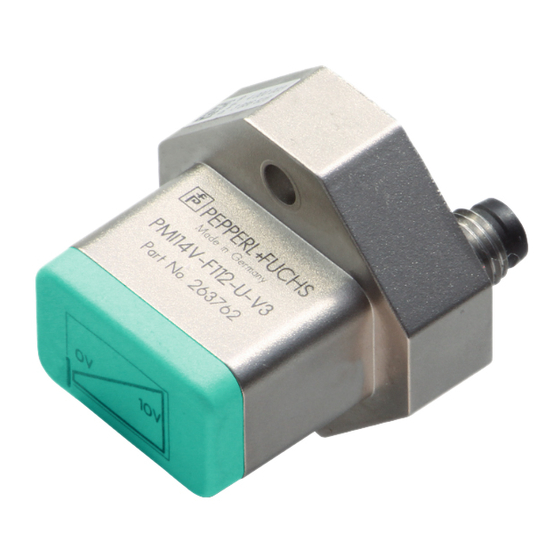
- Page 1 FACTORY AUTOMATION MANUAL PMI14V-F112-...-U-... F112 Inductive Positioning System...
- Page 2 PMI14V-F112-...-U-... With regard to the supply of products, the current issue of the following document is ap- plicable: The General Terms of Delivery for Products and Services of the Electrical Indus- try, published by the Central Association of the Electrical Industry (Zentralverband Elektrotechnik und Elektroindustrie (ZVEI) e.V.) in its most recent version as well as the...
-
Page 3: Table Of Contents
PMI14V-F112-...-U-... Introduction................. 4 Declaration of Conformity............5 Safety ................... 6 Used Symbols ..................6 Intended Use ..................6 General Safety Instructions ..............6 Product Description ..............8 Use and Application................8 Accessories ..................8 4.2.1 Damping Elements ................8 4.2.2 Connection Cable with Plug, 3-Wire........... -
Page 4: Introduction
Introduction Introduction Congratulations You have chosen a device manufactured by Pepperl+Fuchs. Pepperl+Fuchs develops, produces and distributes electronic sensors and interface modules for the market of automation technology on a worldwide scale. Please read the operating instructions carefully before installing this device and putting it into operation. -
Page 5: Declaration Of Conformity
This product was developed and manufactured under observance of the applicable European standards and guidelines. Note! A Declaration of Conformity can be requested from the manufacturer. The product manufacturer, Pepperl+Fuchs GmbH, D-68307 Mannheim, has a certified quality assurance system that conforms to ISO 9001. ISO9001... -
Page 6: Safety
Based on the precise evaluation of several coil systems, the device combines a proven inductive sensor with innovative microcontroller technology. The compact design of the F112 enables position detection tasks to be carried out in a noncontact, wear-free process to a measuring length of 14 mm, even in confined installation locations. - Page 7 PMI14V-F112-...-U-... Safety Note! Disposal Electronic waste is hazardous waste. When disposing of the equipment, observe the current statutory requirements in the respective country of use, as well as local regulations.
-
Page 8: Product Description
Based on the precise evaluation of several coil systems, the device combines a proven inductive sensor with innovative microcontroller technology. The compact design of the F112 enables position detection tasks to be carried out in a noncontact and wear-free process to a measuring length of 14 mm. This includes installation locations where space is limited. -
Page 9: Connection Cable With Plug, 3-Wire
4.2.2 Connection Cable with Plug, 3-Wire Below is a list of 3-wire female single-ended cordsets with a core cross-section of 3 x 0.25 m suitable for establishing the electrical connection for PMI14V-F112-...-U-... devices: Type Straight Right angle... -
Page 10: Installation
Measuring Range of the PMI14V-...-U-... General On delivery, the measuring range of the PMI14V-F112-...-U-... is 14 mm. This is indicated by the framed area at the front of the inductive positioning system. It is possible to reduce the measuring range by parameterizing the sensor. When adjusting the measuring range, the end point of the sensor is fixed;... -
Page 11: Preparation
PMI14V-F112-...-U-... Installation Definition of the Measuring Range/Position The position of the damping element defined by the positioning system relates to half of the width (center) of the damping element. The measuring range begins and ends with the half coverage provided by the damping element when moving lengthwise. -
Page 12: Mounting
2. Check that all items are present and correct based on your order and the shipping documents. If you have any questions, please contact Pepperl+Fuchs. 3. Keep the original packing material in case you need to store or ship the unit at a later time. -
Page 13: Commissioning
Programming the Measuring Range Operating and Display Elements The PMI14V-F112-...-U-... inductive positioning system features a small, slightly recessed push button (1) on the back that is used to program the measuring range. The measuring range starting point that is taught in is saved in the internal nonvolatile memory. -
Page 14: Troubleshooting During Teach-In
PMI14V-F112-...-U-... Commissioning Note! Cancelation if Starting Point Not Confirmed If the starting point that has been taught in is not confirmed within 120 seconds, the inductive positioning system exits "Teach-in mode" and continues operation using the previous value. Troubleshooting during Teach-in... -
Page 15: Maintenance And Repair
PMI14V-F112-...-U-... Maintenance and Repair Maintenance and Repair Maintenance The sensor's transmission properties are stable over long periods. For this reason, regular adjustments to, and maintenance on the sensor itself, are not necessary. Nevertheless check in the course of normal maintenance intervals that the sensor, the actuator and the connector are... -
Page 16: Troubleshooting
If none of the above actions solves the problem, contact the Pepperl+Fuchs Service Center. Have details of the model number and firmware version of the sensor ready if possible. - Page 17 Twinsburg, Ohio 44087 · USA Tel. +1 330 4253555 E-mail: sales@us.pepperl-fuchs.com Asia Pacific Headquarters Pepperl+Fuchs Pte Ltd. Company Registration No. 199003130E Singapore 139942 Tel. +65 67799091 E-mail: sales@sg.pepperl-fuchs.com www.pepperl-fuchs.com Subject to modifications / DOCT-5019 Copyright PEPPERL+FUCHS • Printed in Germany 12/2015...
Need help?
Do you have a question about the F112 and is the answer not in the manual?
Questions and answers