
Related Manuals for Pepperl+Fuchs TCU1100 Series


Summary of Contents for Pepperl+Fuchs TCU1100 Series
- Page 1 VisuNet Computing Unit TCU1100-*/TCU1200-* PCU1100-*/PCU1200-* Elkhart Lake Processor Series Manual...
- Page 2 Phone: +49 621 776 - 0 E-mail: info@de.pepperl-fuchs.com North American Headquarters Pepperl+Fuchs Inc. 1600 Enterprise Parkway Twinsburg, Ohio 44087 Phone: +1 330 425-3555 E-mail: sales@us.pepperl-fuchs.com Asia Headquarters Pepperl+Fuchs Pte. Ltd. P+F Building 18 Ayer Rajah Crescent Singapore 139942 Phone: +65 6779-9091 E-mail: sales@sg.pepperl-fuchs.com https://www.pepperl-fuchs.com...
-
Page 3: Table Of Contents
VisuNet Computing Unit Contents History of the Manual ....................4 Introduction........................ 5 Content of this Document ................5 Target Group, Personnel ................5 Symbols Used ....................6 Product Description ....................7 Overview......................7 Technical Data....................10 Dimensions and Type Labels..............15 Scope of Delivery.................. -
Page 4: History Of The Manual
VisuNet Computing Unit History of the Manual History of the Manual The following editions of the manual have been released: Version Comments 09/2023 First edition... -
Page 5: Introduction
VisuNet Computing Unit Introduction Introduction Content of this Document This document contains information that you need in order to use your product throughout the applicable stages of the product life cycle. These can include the following: • Product identification • Delivery, transport, and storage •... -
Page 6: Symbols Used
VisuNet Computing Unit Introduction Symbols Used This document contains symbols for the identification of warning messages and of informative messages. Warning Messages You will find warning messages, whenever dangers may arise from your actions. It is mandatory that you observe these warning messages for your personal safety and in order to avoid prop- erty damage. -
Page 7: Product Description
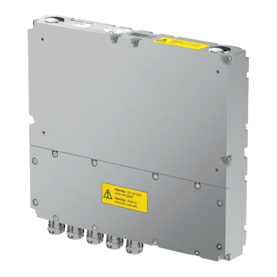
Zones 1/21 and 2/22 and Class I/II, Div. 2 and Class III. Connected to Pepperl+Fuchs display units, the TCU and PCU devices serve as thin-client- or PC-based computing units. The TCU devices run VisuNet RM Shell firmware and allow users to easily connect to a host system via Ethernet. - Page 8 VisuNet Computing Unit Product Description Component Overview Description Tightening Torque Terminal compartment cover Breather vent 10 mounting holes Terminal compartment Optional cable glands Standard cable glands for 5 Nm power supply, USB Ex e, Ethernet, 2 x USB Ex i 12 x mounting screws for ter- 1.5 Nm minal compartment cover...
- Page 9 VisuNet Computing Unit Product Description Danger! Accumulation of condensed water within the housing can cause a short and result in an igni- tion. A blocked breather vent cannot provide ventilation or drainage. Do not block or restrict the breather vent! Do not insert any sharp objects into the breather vent! Cable Gland Connection Layout The cable glands have different inlays in different sizes.
-
Page 10: Technical Data
1 x fiber optic 1000BASE-SX (Mulitmode) or 1 x fiber optic 1000BASE-LX (Singlemode) 1 x USB 2.0 (Ex e) 2 x USB 1.1 (Ex i; intended for Pepperl+Fuchs keyboard and mouse) 1 x DC or AC power in (via power supply unit) - Page 11 30 g , 11 ms all axis, IEC 60068-2-27 Vibration restistance 5 ... 100 Hz 1 G, 12 m/s Mechanical specifications Degree of protection IP66 (when mounted on the display unit from Pepperl+Fuchs) Material Housing anodized aluminum Seal EPDM Mass approx.
- Page 12 1 x fiber optic 1000BASE-SX (Multimode) or 1 x fiber optic 1000BASE-LX (Singlemode) 1 x USB 2.0 (Ex e) 2 x USB 1.1 (Ex i; intended for Pepperl+Fuchs keyboard and mouse) 1 x DC or AC power in (via power supply unit)
- Page 13 ATEX/IECEx Marking Thin Client Unit TCU1100-J1-* PC Unit PCU1100-J1-* Pepperl+Fuchs SE Lilienthalstraße 200, 68307 Mannheim, Germany ATEX: BVS 16 ATEX E 083 X II 2G Ex eb q [ib] IIC T4 IP66 Gb II 2D Ex tb [ib] IIIC T85°C IP66 Db IECEx: IECEx BVS 16.0060X...
- Page 14 Product Description Thin Client Unit TCU1200-J2-* PC Unit PCU1200-J2-* Pepperl+Fuchs SE Lilienthalstraße 200, 68307 Mannheim, Germany ATEX: BVS 16 ATEX E 082 X II 3G Ex ec [ib] IIC T4 IP66 Gc II 3D Ex tc [ib] IIIC T85°C IP66 Dc IECEx: IECEx BVS 16.0060X...
-
Page 15: Dimensions And Type Labels
VisuNet Computing Unit Product Description Dimensions and Type Labels Dimensions 44.8 Labels The following labels are present on the TCU/PCU. Warning marking "Warning – Do not open! This container has Warning - Do not open! been permanently sealed and cannot be repaired."... -
Page 16: Scope Of Delivery
VisuNet Computing Unit Product Description Warning marking "Warning – Hot surface! Do not touch!" "Avertissement – Surface chaude! Ne pas Warning - Hot surface! toucher!" Do not touch! Type label TCU/PCU sample Scope of Delivery • Thin Client Unit / Personal Computer Unit •... -
Page 17: Installation
VisuNet Computing Unit Installation Installation Watch the tutorial for the electrical installation steps on YouTube by scanning the QR code or by clicking on the following link: English Version: https://www.youtube.com/watch?v=wBAZA-PY_OI Figure 4.1 German Version: https://www.youtube.com/watch?v=Gp1pUhQ32SI Figure 4.2 General Installation Requirements •... -
Page 18: Terminal Compartments
VisuNet Computing Unit Installation Terminal Compartments Danger! Danger of Explosion Disconnecting cables too quickly may trigger an ignition, as device-internal cable capacitances need some time to discharge. After de-energizing, wait 3 minutes before opening the compartment room or disconnecting the device from the display unit. - Page 19 VisuNet Computing Unit Installation Terminal Compartment Ex e X1: Power Supply +24 V DC / USB Ex e Terminal X1.1 Power Supply X1.2 X1.3 X1.4 X1.5 USB Ex e X1.6 X1.7 X1.8 The table below gives an overview of the 2 color schemes: The Ethernet terminal assignment can be done either by EIA/TIA-568A or by EIA/TIA-568B color scheme.
- Page 20 VisuNet Computing Unit Installation Note When the fiber-optic interface is installed, no terminal connections are available at X2. Multimode: Fiber Optic Specifications Minimum cable requirement OM2 (50/125 µm) Data rate 1 Gb Max. distance 550 m Mode Multimode Category 1000BASE-SX Link budget 3 dB (in addition to cabling with 550 m OM2)—if counterpart uses Horizon GXP,...
- Page 21 VisuNet Computing Unit Installation Terminal Compartment Ex i X3: USB for Keyboard and Mouse EXTA4 Ex i Peripheral Terminal Signal Assignment Color coding Name Direction X3.1 Supply 1st USB Ex i VCC (Ui) green (Keyboard) X3.2 gray X3.3 brown X3.4 Supply yellow X3.5...
- Page 22 VisuNet Computing Unit Installation X4 or X5: "S3" Scanner Option for 1-D Handheld Barcode Reader IDM160*, IDM-Z1-160- *, Base Station IDMx61-B-N0* Ex i and IDM-Z1-x61-B-N0* Cable Terminal Signal Name Direction Assignment Color coding Pin M12 con- nector Xx.1 Supply green Xx.2 Supply brown...
- Page 23 VisuNet Computing Unit Installation DATL-IDM-DB-S-XX00-N0 Connection Cable for IDM-Z1-260-D-1D-* Figure 4.7 X4 or X5: "S5" RS-232 interface Option for miscellaneous devices and peripherals Ex i Terminal Compartment Ex i Terminal Signal Name Direction Xx.1 Supply Xx.2 Xx.3 Xx.4 Xx.5 Supply Xx.6 Xx.7 Xx.8...
- Page 24 VisuNet Computing Unit Installation X4 or X5: RS-232 Option "S1" Ex e Terminal Signal Name Direction Xx.1 Xx.2 Xx.3 Xx.4 Xx.5 Xx.6 Xx.7 Xx.8 RS-232 Specifications Cable Shielded 0.75 mm (e.g., LiYCY 4 x 0.75) Max. distance (acc. standard) 15 m Max.
- Page 25 VisuNet Computing Unit Installation RS-485 Cabling Possible network connections include the following: • Full duplex • Terminated (120 Ohm) full duplex • Half duplex • Terminated half duplex Normal Full Duplex Terminated Full Duplex Figure 4.8 Full duplex cabling Normal Half Duplex Terminated Half Duplex Figure 4.9 Half duplex cabling...
-
Page 26: Mechanical Installation
Watch the tutorial for this installation step on Youtube by scanning the QR code or by clicking on the following link: https://www.youtube.com/watch?v=xk7Kv-lNdHM Figure 4.10 Mounting the TCU/PCU onto the Display Unit Ensure the correct position of the TCU/PCU. Place the TCU/PCU with the Pepperl+Fuchs connector above the Pepperl+Fuchs socket on the back of the display unit. - Page 27 VisuNet Computing Unit Installation Carefully push the Pepperl+Fuchs connector into the Pepperl+Fuchs socket. Use the mounting screws to fasten the PCU/TCU onto the display unit. Tighen the screws to 2 Figure 4.11 Mounting the TCU/PCU onto the display unit Caution! Damage to pins Carefully align the PCU/TCU with the DPU when connecting the units.
-
Page 28: Bios Settings
VisuNet Computing Unit BIOS Settings BIOS Settings Caution! Warranty Access to the BIOS is prohibited. Any access to the BIOS is at your own risk and is not covered by the warranty for repairs. Arbitrary changes to BIOS settings may affect device functionality. The BIOS is set according to customer requirements by default. -
Page 29: Factory Reset
VisuNet Computing Unit Factory Reset Factory Reset VisuNet PCUs and TCUs can be reset to their original factory configurations. TCUs that use VisuNet RM Shell firmware can be reset via functions that are available in RM Shell. Refer to RM Shell documentation for instructions on performing a factory reset. PCUs that use a pre-installed Windows®... -
Page 30: Appendix
Appendix System Health Monitoring When using the thin client unit in combination with the Pepperl+Fuchs display units DPU1100 / DPU1200-* there is a health monitoring for possible hardware errors that helps you to indicate what is wrong with the hardware components. - Page 31 VisuNet Computing Unit Appendix Temperature Error (too High) Indication Problem Solution "Brightness +" button solid Temperature too high (moni- Check if ambient temperature white tored only during booting up) surrounding the panel Power button solid red exceeds the panel's allowed operating temperature.
-
Page 32: Ul Control Drawing
VisuNet Computing Unit Appendix UL Control Drawing Connections Hazardous Location Hazardous Location Class I, Division 2, Groups A, B, C, D; T4 Class I, Division 2, Groups A, B, C, D; T4 Class II, Division 2, Groups F, G; T4 Class II, Division 2, Groups F, G;... - Page 33 Pepperl+Fuchs Quality Download our latest policy here: www.pepperl-fuchs.com/quality www.pepperl-fuchs.com © Pepperl+Fuchs · Subject to modifications / DOCT-8948...
Need help?
Do you have a question about the TCU1100 Series and is the answer not in the manual?
Questions and answers