Table of Contents
Advertisement
Quick Links
Advertisement
Table of Contents

Subscribe to Our Youtube Channel
Related Manuals for Pepperl+Fuchs PXV100AQ-F200-R4-V19


Summary of Contents for Pepperl+Fuchs PXV100AQ-F200-R4-V19
- Page 1 PXV100AQ-F200-R4-V19 Data Matrix Positioning System Manual...
- Page 2 Phone: +49 621 776 - 0 E-mail: info@de.pepperl-fuchs.com North American Headquarters Pepperl+Fuchs Inc. 1600 Enterprise Parkway Twinsburg, Ohio 44087 Phone: +1 330 425-3555 E-mail: sales@us.pepperl-fuchs.com Asia Headquarters Pepperl+Fuchs Pte. Ltd. P+F Building 18 Ayer Rajah Crescent Singapore 139942 Phone: +65 6779-9091 E-mail: sales@sg.pepperl-fuchs.com https://www.pepperl-fuchs.com...
-
Page 3: Table Of Contents
PXV100AQ-F200-R4-V19 Contents Introduction........................ 5 Content of this Document ................5 Target Group, Personnel ................5 Symbols Used ....................6 Safety Information ..................... 7 Intended Use ....................7 Useful Lifetime ....................7 Product Description ....................9 Components of the Positioning System ............9 Use and Application .................. - Page 4 PXV100AQ-F200-R4-V19 Contents Connecting the Read Head to the PUS Evaluation Unit ......50 The RS-485 Interface ...................51 Commissioning the Read Head with the PUS Evaluation Unit via safeControl Expert.................52 Maintenance ......................56 Maintenance ....................56 Testing......................56 Cleaning ......................57 Repairs ......................57 Disposal ........................58...
-
Page 5: Introduction
PXV100AQ-F200-R4-V19 Introduction Introduction Content of this Document This document contains information required to use the product in the relevant phases of the product life cycle. This may include information on the following: • Product identification • Delivery, transport, and storage •... -
Page 6: Symbols Used
PXV100AQ-F200-R4-V19 Introduction Symbols Used This document contains symbols for the identification of warning messages and of informative messages. Warning Messages You will find warning messages, whenever dangers may arise from your actions. It is mandatory that you observe these warning messages for your personal safety and in order to avoid prop- erty damage. -
Page 7: Safety Information
Intended Use The Data Matrix Positioning System is the positioning system in the Pepperl+Fuchs incident light process. The heart of the system is the read head, which consists of a camera module with an internal illumination unit. This enables the read head to detect position markers printed onto a self-adhesive code tape in the form of 2-D Data Matrix codes. - Page 8 PXV100AQ-F200-R4-V19 Safety Information It is therefore clear that this failure calculation only applies to components that have this con- stant range, and that the validity of the calculation is limited to the useful lifetime of each com- ponent. It is assumed that the majority of early failures are detected during installation and that, there- fore, a constant failure rate applies during the useful lifetime.
-
Page 9: Product Description
The positioning system described in this manual consists of the following components: Figure 3.1 System overview • Read head PXV100AQ-F200-R4-V19, hereinafter referred to as "read head" in this docu- ment. • 2-colored Data Matrix code tape PXV*-AA25-*, hereinafter referred to as "Data Matrix code tape"... -
Page 10: Use And Application
Use and Application Data Matrix Positioning System The Data Matrix Positioning System is the positioning system in the Pepperl+Fuchs incident light process. The heart of the system is the read head, which consists of a camera module with an internal illumination unit. This enables the read head to detect position markers printed onto a self-adhesive code tape or metal code bar in the form of 2-D Data Matrix codes. - Page 11 PXV100AQ-F200-R4-V19 Product Description Data Matrix Code Tape The Data Matrix code tape is mounted on a fixed part of the plant (e.g., the wall of an elevator shaft, or the rail on a monorail conveyor). The read head is mounted on a "carrier" that moves parallel to the code tape (e.g., on the elevator cabin or on the chassis of a monorail conveyor).
- Page 12 PXV100AQ-F200-R4-V19 Product Description Data Matrix Metal Code Bars The metal code bars are an extension of the conventional code tapes and are made of robust aluminum. Compared to conventional code tapes, the metal code bars are more robust and resistant to external influences. They are specifically designed for use in environments where conventional code tapes can be quickly damaged due to the conditions in which they are used.
-
Page 13: Led Indicators And Operating Elements
PXV100AQ-F200-R4-V19 Product Description LED Indicators and Operating Elements The read head has seven indicator LEDs for visual function checks and quick diagnosis. Activate the alignment aid and parameterization mode using the two control buttons on the back of the device. - Page 14 = 2 Hz for 3 sec flash Green, 1 sec Flash- Code card detected = 2 Hz for 3 sec flash Time lock for buttons disabled Lights Lights Internal error Return to Pepperl+Fuchs Table 3.1 LED Indicators x = LED status has no meaning...
-
Page 15: Accessories
In harsh ambient conditions, appropriate Pepperl+Fuchs accessories can be used to extend the service life of these products. Model number... -
Page 16: Transport And Storage
PXV100AQ-F200-R4-V19 Transport and Storage Transport and Storage Retain the original packaging. Always store or transport the device in the original packaging to protect it from electrostatic discharge (ESD) and mechanical damage. -
Page 17: Planning
Before selecting and using the product, the plant designer must evaluate whether this product is suitable for the intended application. Pepperl+Fuchs has no influence on the selection and use of this product. The warranty therefore only covers the consistent quality of the product. -
Page 18: Safety-Related Reading Range Of The Read Head
PXV100AQ-F200-R4-V19 Planning Safety-Related Reading Range of the Read Head The safety-related reading range is the part of the field of view of the read head in which Data Matrix codes can be decoded. The safety-related reading range is smaller than the field of view. -
Page 19: Read Head Orientation For The Data Matrix Code Tape
PXV100AQ-F200-R4-V19 Planning Read Head Orientation for the Data Matrix Code Tape The following section shows the number of visible Data Matrix codes depending on the read distance. The read head in the image is positioned in an orientation of 0° to the Data Matrix code tape. -
Page 20: Characteristics Of The Data Matrix Codes And Code Redundancy
PXV100AQ-F200-R4-V19 Planning Characteristics of the Data Matrix Codes and Code Redundancy Characteristics of the Data Matrix Code The position marks in the code tape contain information about the absolute position of the tape, and serve as reference points for the read head. The read head uses its camera to capture the image of the code and uses the information contained in the position marks to determine the exact position of the code in the camera image. - Page 21 PXV100AQ-F200-R4-V19 Planning Code Redundancy A maximum of three consecutive Data Matrix codes may be contaminated. As soon as at least one single Data Matrix code is detected in the field of view, the position output x, y can be per- formed.
-
Page 22: Read Head Orientation
PXV100AQ-F200-R4-V19 Planning Read Head Orientation 5.6.1 Horizontal Tolerance – Read Distance z The read head offers the highest possible depth of field for cornering in horizontal curves and mounting at different reading distances. If the read head is mounted too close or too far away on the Data Matrix code tape, a warning message is issued. -
Page 23: Vertical Tolerance - Height Tolerance Y
PXV100AQ-F200-R4-V19 Planning 5.6.2 Vertical Tolerance - Height Tolerance y If the read head leaves the zero line (y = 0) when traversing along the Data Matrix code tape (x- axis) in the y direction, a warning message is output from a defined threshold value. The read head continuously measures its position in relation to the Data Matrix code tape (1) and com- pares the current threshold value. - Page 24 PXV100AQ-F200-R4-V19 Planning Set Point y = 0 The read head is in an optimal position with respect to the Data Matrix code tape. +y₀ 8 (wrn on) 7 (wrn off) -7 (wrn off) -8 (wrn on) -y₀ Figure 5.4 Green: recommended range Limit Value y >...
- Page 25 PXV100AQ-F200-R4-V19 Planning No-Position The read head is positioned too low in relation to the Data Matrix code tape and loses the posi- tion. The message "No-Position" is output. +y₀ +7/+8 -7/-8 -y₀ Figure 5.7 Red: Range in which a "No-position" message is set...
-
Page 26: Inclination Angle
PXV100AQ-F200-R4-V19 Planning 5.6.3 Inclination Angle Inclination angle of ± 30° possible. It should be noted that the extreme tolerances do not apply in total. Simultaneous tilting possible in both x and y directions. Note Simultaneous tiltings in the x and y directions are allowed. It is important to note that tilting the sensor shifts the reading window. -
Page 27: Rotational Tolerance In The Z Axis
PXV100AQ-F200-R4-V19 Planning Note Using the alignment aid, the center of the optical axis of the read head can be aligned with the center of the Data Matrix codes. This ensures that the reading window covers the Data Matrix codes. . -
Page 28: Expansion Joints / Gaps
PXV100AQ-F200-R4-V19 Planning Expansion Joints / Gaps To compensate for temperature-related length changes in plant structures, expansion joints are usually required for longer tracks. If a Data Matrix code tape is applied at such locations, we recommend that you interrupt the code tape at the edge of the expansion joint and continue with a fully readable Data Matrix code tape. - Page 29 PXV100AQ-F200-R4-V19 Planning Maximum Gap for Read Head Orientation 90°/270° 15 mm 15 mm 2 mm 2 mm Figure 5.12 Expansion Joints / Gaps Note Please note that with this alignment of the read head, the code redundancy or the gap width is reduced.
- Page 30 PXV100AQ-F200-R4-V19 Planning 1 missing Data Matrix code 000 000.0 m PXV-AA25 www.pepperl-fuchs.com D = 25 mm 2 missing Data Matrix codes 000 000.0 m PXV-AA25 www.pepperl-fuchs.com D = 45 mm 3 missing Data Matrix codes 000 000.0 m PXV-AA25 www.pepperl-fuchs.com...
- Page 31 PXV100AQ-F200-R4-V19 Planning Case 1 - Continuous Bonding Glue the Data Matrix code tape continuously and cut out the codes in the area of the gap. Advantage: The codes remain continuously in the same position grid. Therefore, there is no difference between the logical and mechanical position.
- Page 32 PXV100AQ-F200-R4-V19 Planning Case 2 - Continuous Continuation Glue the Data Matrix code tape up to the gap and cut out the codes in the area of the gap. Con- tinue the code tape at the continuous component. Advantage: In the case of extremely wide gaps, the Data Matrix code tape can be optimally mounted along the mechanical gap.
- Page 33 PXV100AQ-F200-R4-V19 Planning The x value remains constant at its historical value and shows a hysteresis of 21 mm. When the center of the image approaches the next code, there is a jump. Case 4 - Gap is too large For a short period of time, the read head outputs the message "No Position."...
- Page 34 PXV100AQ-F200-R4-V19 Planning Thermal Expansion Note Thermal expansion coefficient The thermal expansion coefficient of the attached code tape depends on the thermal expansion coefficient of the surface. When planning the system, consider the worst-case scenario that can be caused by thermal expansion of the surface and adjust the Data Matrix code tape to fit the expansion joint accord- ingly.
-
Page 35: Behavior Of The Read Head When Cornering
PXV100AQ-F200-R4-V19 Planning Behavior of the Read Head When Cornering Minimum Curve Radius When planning your system, please ensure that you do not fall below a minimum bending radius of 100 mm for horizontal curves. Figure 5.20... - Page 36 PXV100AQ-F200-R4-V19 Planning Horizontal Curves If the read head is not mounted in the application's axis of rotation (1), the following situation can occur for horizontal curves: Figure 5.21 • Depending on the curve (right or left curve), the read head moves toward the code tape (1) or away from the code tape (1).
- Page 37 PXV100AQ-F200-R4-V19 Planning Inclines and Declines If the read head is not mounted in the rotation axis (1) of the application, the following situation may occur on inclines and declines: Figure 5.22 • The reading window (2) is tilted relative to the Data Matrix code tape (3). Secure position detection is only guaranteed if at least one Data Matrix code can be read.
-
Page 38: Installation And Commissioning
PXV100AQ-F200-R4-V19 Installation and Commissioning Installation and Commissioning General The positioning system is safe if it is mounted and set up in accordance with the provisions of these instructions, the read head works properly, and the Data Matrix code tape is mounted correctly so that it is stationary and readable. - Page 39 PXV100AQ-F200-R4-V19 Installation and Commissioning Note Butt Edges If you attach another Data Matrix code tape at the end of a previous Data Matrix code tape, the code pattern of 20 mm must be retained. Note Application Device To facilitate the application of the code tape, we recommend the use of a mechanical application device.
- Page 40 PXV100AQ-F200-R4-V19 Installation and Commissioning Note When removing the protective film from the code tape, make sure that the code tape is not inadvertently glued to an unwanted place. Also, ensure that no folds or waves are created in the code tape when sticking it down. The protective film should only be removed in small sections at a time.
-
Page 41: Mounting And Alignment Of The Read Head
PXV100AQ-F200-R4-V19 Installation and Commissioning Mounting and Alignment of the Read Head Mounting and alignment of the read head are critical steps to ensure reliable and accurate cap- ture of the Data Matrix codes. The read head must be mounted in such a way that it has a clear view of the Data Matrix codes and is not obscured by other objects or machines. -
Page 42: Mounting The Read Head
PXV100AQ-F200-R4-V19 Installation and Commissioning 6.3.1 Mounting the Read Head The mounting and alignment of the read head for the acquisition of Data Matrix codes requires precise fine adjustment of the read head. The mounting bracket PCV-MB1 is suitable for this purpose. - Page 43 PXV100AQ-F200-R4-V19 Installation and Commissioning Mounting the Mounting Bracket on the Moving System Part Figure 6.3 Mounting bracket (PCV-MB1) Position the mounting bracket in the direction of the Data Matrix code tape so that the read head can be finely adjusted afterward.
- Page 44 When mounting the read head, it is essential to pay attention to the direction of movement. The sensor always moves in the x direction. When mounting, ensure that the "PEPPERL+FUCHS" logo and the positioning targets are placed below the Data Matrix codes. The position values increase in the x direction.
-
Page 45: Alignment Of The Read Head
PXV100AQ-F200-R4-V19 Installation and Commissioning 6.3.2 Alignment of the Read Head Two tools are available for the exact alignment of the read head to the Data Matrix code tape: • The alignment guide: It ensures the exact distance of the read head to the Data Matrix code tape, and the alignment of the optical axis of the read head to the center of the Data Matrix codes. - Page 46 PXV100AQ-F200-R4-V19 Installation and Commissioning Adjust the alignment of the read head until the alignment tip of the guide is aligned exactly with the center of the Data Matrix codes. Note the maximum inclination angle of ± 30° on the x or y axis. Make sure that the read head is aligned within the permissible angular tolerances, see chapter 5.6.3.
- Page 47 PXV100AQ-F200-R4-V19 Installation and Commissioning Aligning the Read Head with an Electronic Alignment Aid The read head has an integrated alignment aid, which enables easy alignment of the read head in the y and z direction to the Data Matrix code tape. The alignment aid can only be activated within 10 minutes of switching on the read head.
-
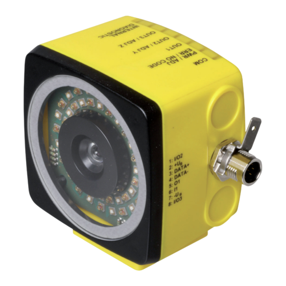
Page 48: Electrical Connection
Figure 6.9 Connector assignment Color assignment Pepperl+Fuchs single-ended female cordsets are manufactured in accordance with EN60947- 5-2. When using a type V19-... single-ended female cordset with an open cable end ( ), the fol- lowing color assignment applies: Connection pin... - Page 49 PXV100AQ-F200-R4-V19 Installation and Commissioning Shielding Cables The shielding of connection lines is required to suppress electromagnetic interference. Estab- lishing a low resistance or low impedance connection with the protective conductor or equipo- tential bonding circuit is a particularly important factor in ensuring that these interference currents do not become a source of interference themselves.
-
Page 50: Connecting The Read Head To The Pus Evaluation Unit
PXV100AQ-F200-R4-V19 Installation and Commissioning Connecting the Read Head to the PUS Evaluation Unit This chapter is intended to provide a simplified overview of the connection of the safePXV/PUS read head to the PUS evaluation unit. Warning! Read the information in this documentation carefully and observe the information in the Installa- tion Handbook for the PUS evaluation unit. -
Page 51: The Rs-485 Interface
PXV100AQ-F200-R4-V19 Installation and Commissioning The RS-485 Interface The read head is equipped with an RS-485 interface for communication purposes, i.e., param- eterizing the read head functions or reading out current process data during operation. This interface is operated in 8-E-1 operating mode and is fitted with a terminator that can be acti- vated or deactivated by parameterizing the sensor head. -
Page 52: Commissioning The Read Head With The Pus Evaluation Unit Via Safecontrol Expert
For more information and detailed instructions, we recommend that you read the safeControl Expert configuration software manual. Perform Commissioning with safeControl Expert Download the safeControl Expert software from the Pepperl+Fuchs website and follow the installation steps. Figure 6.10... - Page 53 PXV100AQ-F200-R4-V19 Installation and Commissioning Figure 6.12 Select the PUS evaluation unit "PUS-F161-X-PXV" from the library and drag and drop it into the "Connection diagram" [Terminal Scheme]. Figure 6.13 Open the properties window of the PUS evaluation unit and select the configuration "PXV" (1) under "Encoder Combination - Axis 1."...
- Page 54 PXV100AQ-F200-R4-V19 Installation and Commissioning Switch to the "Function plan" tab (1) and drag and drop axis 1 with PXV read head (2) into the function plan. Figure 6.15 Configure the axis settings according to your requirements. Figure 6.16 Example •...
- Page 55 PXV100AQ-F200-R4-V19 Installation and Commissioning Note For more information on the individual values, refer to the safeControl Expert manual.
-
Page 56: Maintenance
PXV100AQ-F200-R4-V19 Maintenance Maintenance Caution! Gerät kann bei längerer Betriebsdauer warm werden Nach längerer Betriebszeit weisen die Metallflächen (Stecker) und das Gehäuse des Sensors eine erhöhte Temperatur zur Umgebung auf. Dies ist bei Servicearbeiten zu beachten. Lassen Sie das Gerät abkühlen, bevor Sie es hand- haben. -
Page 57: Cleaning
PXV100AQ-F200-R4-V19 Maintenance Cleaning Caution! Material damage due to improper cleaning Treating surfaces with the wrong cleaning agents and liquids can damage the surface and therefore disrupt the function of the read head or make the Data Matrix codes illegible. Cleaning the Read Head Check that the components are securely mounted and that optical surfaces are clean. -
Page 58: Disposal
PXV100AQ-F200-R4-V19 Disposal Disposal The device, built-in components, packaging, and any batteries contained within must be disposed in compliance with the applicable laws and guidelines of the respective country. - Page 59 Pepperl+Fuchs Quality Download our latest policy here: www.pepperl-fuchs.com/quality www.pepperl-fuchs.com © Pepperl+Fuchs · Subject to modifications / DOCT-8688...
Need help?
Do you have a question about the PXV100AQ-F200-R4-V19 and is the answer not in the manual?
Questions and answers