
Related Manuals for Renishaw FORTiS-N


Summary of Contents for Renishaw FORTiS-N
- Page 1 Installation guide M-6725-9026-02-A FORTiS-N enclosed encoder system ™ Functional Safety installation guide and safety manual www.renishaw.com/fortisdownloads #renishaw...
- Page 2 This page is left intentionally blank. FORTiS-N Functional Safety enclosed encoder system – original instructions...
-
Page 3: Table Of Contents
Proof testing ......................12 www.renishaw.com... - Page 4 14.6 Spar mounting options ....................29 FORTiS-N Functional Safety enclosed encoder system – original instructions...
- Page 5 16.4 Siemens DRIVE-CLiQ serial interface ..................44 www.renishaw.com...
-
Page 6: Legal Notices
US6465773 SAFETY 1.2 Terms and Conditions and Warranty The FORTiS-N FS encoder system is suitable for use in a Category 3 performance level d (PLd) Unless you and Renishaw have agreed and signed a separate written agreement, the equipment application in compliance with ISO 13849‑1 and in a safety integrity level 2 (SIL2) application in and/or software are sold subject to the Renishaw Standard Terms and Conditions supplied with compliance with IEC 61508‑1 and IEC 61800‑5‑2 when installed and operated in accordance... -
Page 7: Federal Code Of Regulation (Cfr) Fcc Part 15 - Radio Frequency Devices
1.5 Federal Code Of Regulation (CFR) FCC Part 15 Supplier’s Declaration of Conformity – RADIO FREQUENCY DEVICES 47 CFR § 2.1077 Unique Identifier: FORTiS-N FCC Compliance Statement Responsible Party – U.S. Contact Information 47 CFR Section 15.19 Renishaw Inc. 1001 Wesemann Drive This device complies with part 15 of the FCC Rules. -
Page 8: Packaging
M-6725-9212 with multiple readheads The use of this symbol on Renishaw products and/or accompanying documentation indicates that the product should not be mixed with general household waste upon disposal. It is the responsibility of the end user to dispose of this product at a designated collection point for waste electrical and electronic equipment (WEEE) to enable reuse or recycling. -
Page 9: Definitions
ESD handling The ESD Susceptibility Symbol consists of a triangle, a reaching The FORTiS-N FS encoder system is designed to be used as part of a safety-related control hand, and a slash through the reaching hand. The triangle means system as specified by the system manufacturer. It is the responsibility of the system manufacturer “Caution”... -
Page 10: Functional Safety Data Declaration
Lifetime/replacement limits 20 years – Siemens DRIVE-CLiQ serial interface 6.02E-07 5.42E-07 The FORTiS-N FS encoder system provides safe position data that supports the following safety 6.02E-08 sub‑functions defined by IEC 61800‑5‑2: Not applicable due to continuous • Safe stop 1 (SS1) and Safe stop 2 (SS2) demand mode PFH (per hour) –... -
Page 11: Safety Function
The tolerance for raising a fault condition is relative to the safe position determined by the system manufacturer. • Faults caused by cutting and reconnecting the cable or the use of a non-Renishaw cable that is not approved. •... -
Page 12: Evaluation Unit Monitoring
• Repair of the FORTiS-N FS encoder system is only by replacement of parts. each readhead in the FORTiS-N FS encoder system, and in the case of fault detection place the • The replacement parts must have the same part number as the original parts. -
Page 13: Certification
EUD 2021-00819 FORTiS-N FS encoder system EU based person authorised to compile the technical file: Renishaw (Ireland) DAC, Swords Business Park, Swords, Co. Dublin, K67 FX67, Ireland. Functional Safety Certificate No. FSC003 This declaration of conformity is issued under the sole responsibility of the manufacturer, Renishaw plc. The object of the declaration is identified below: Product name: FORTiS-S FS and FORTiS-N FS enclosed encoder system ™... -
Page 14: Summary Of Uk Declaration Of Conformity
Summary of UK declaration of conformity UKD 2021-00819 This declaration of conformity is issued under the sole responsibility of the manufacturer, Renishaw plc. The object of the declaration is identified below: Product name: FORTiS-S FS and FORTiS-N FS enclosed encoder system ™ ™ Description: Enclosed linear FS readhead and scale assembly Part no.:... -
Page 15: Overview Of The Fortis-N Fs Encoder System
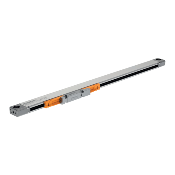
This system is an enclosed linear optical encoder designed for use in harsh industrial environments where high-precision feedback and metrology are required. Based upon Renishaw’s award-winning absolute technology, the rugged non-contact design has no internal moving parts, such as bearings or wheeled readhead carriages, thus improving the overall reliability. -
Page 16: Parts List
FORTiS-N FS quality inspection Certifies specific encoder performance and provides traceability certificate Yellow Functional Safety card Shows the web address for accessing the installation guide Siemens DRIVE-CLiQ interface Included with Siemens-only versions of FORTiS (see section 16.4 on page 44) FORTiS-N Functional Safety enclosed encoder system – original instructions... -
Page 17: Not Included / Required Tools
All fastenings (except air bung and cable connection) should be secured with Loctite 243 If an air bung requires replacement or repositioning it should be secured with Loctite 222. Loctite 222 The cable connector should also be secured with Loctite 222. www.renishaw.com... -
Page 18: Optional Extras
Further information relating to cables for the FORTiS encoder range can be found in the data sheet 10.3.1 Mounting aid (Renishaw part no. A-9768-3586) Cables for FORTiS absolute encoders (Renishaw part no. L-9517-0069). This can be downloaded from our website www.renishaw.com/fortisdownloads... -
Page 19: Storage And Handling
11 Storage and handling IMPORTANT: Handle carefully to avoid damage to the location faces when unpacking and installing. Storage temperature Operating temperature 95% relative humidity (non-condensing) to IEC 60068-2-78 −20 ºC to +70 ºC 0 ºC to +50 ºC Handling instructions www.renishaw.com... -
Page 20: Installation Drawings
* M4 for short end cap version. X = Machine guideway/axis datum NOTES: Side elevations show alternative mounting orientations. Alignment pin and machine edge mounting options to mate directly to the top face of the extrusion. FORTiS-N Functional Safety enclosed encoder system – original instructions... -
Page 21: Mounting Orientations - Standard End Caps
NOTES: Side elevation shows alternative mounting orientation. Side elevations show alternative mounting orientations. Extrusion mounting can be machine edge or dowel pins. Alignment pin and machine edge mounting options to mate directly to the top face of the extrusion. www.renishaw.com... -
Page 22: Fortis System Installation Drawing - Standard End Caps
ML = Measuring length P = Gauging points for alignment S = Start of measuring length 920 1020 1140 1240 1340 1440 1540 1640 1740 1840 2040 X = Machine guideway/axis datum FORTiS-N Functional Safety enclosed encoder system – original instructions... -
Page 23: Fortis System Installation Drawing - Short End Caps
D = Required mounting dimensions L = LED set-up illumination ML = Measuring length P = Gauging points for alignment S = Start of measuring length 920 1020 1140 1240 1340 1440 1540 1640 1740 1840 2040 X = Machine guideway/axis datum www.renishaw.com... -
Page 24: Product Specification
Serial interface Resolution 3 µm BiSS Safety, Siemens DRIVE-CLiQ 1 nm 5 µm BiSS Safety, Siemens DRIVE-CLiQ 10 nm 50 nm IMPORTANT: Specifications are subject to the correct installation procedures as set out in this installation guide. If in doubt, contact your local Renishaw representative. FORTiS-N Functional Safety enclosed encoder system – original instructions... -
Page 25: Installation Procedure - Extrusion
If a suitable reference edge or dowel pins are not available then we recommend that the extrusion is checked against a dial gauge to ensure parallelism to the machine axis. For measuring lengths > 620 mm a mounting spar is recommended; please refer to sections 14.4, For measuring lengths greater than 620 mm Renishaw recommends the use of a mounting 14.5 14.6 for full details. (If required, a mounting spar can be used for measuring lengths under spar (see section 14.4... -
Page 26: Extrusion Installation Without Mounting Spar
M8 screws placed in the end cap the mounting edge/dowel pins. Position the encoder to align the mounting holes. mounting holes. NOTE: Secure fastenings with Loctite 243. 20 Nm Tighten to a torque of 20 Nm. FORTiS-N Functional Safety enclosed encoder system – original instructions... -
Page 27: Installation With Mounting Spar
14.4 Installation with mounting spar Renishaw recommends the use of a mounting 0.1 mm spar where measuring lengths are greater than 620 mm. This requires encoders with short end caps. Where measuring lengths are less than 620 mm, if short end caps are specified, the mounting spar should also be used. If in doubt, please contact your local Renishaw representative. -
Page 28: Mounting Spar Installation Drawing
D = Required mounting dimensions 920 1020 1140 1240 1340 1440 1540 1640 1740 1840 2040 ML = Measuring length 37.5 910 1010 P = Gauging points for alignment X = Machine guideway/axis datum FORTiS-N Functional Safety enclosed encoder system – original instructions... -
Page 29: Spar Mounting Options
14.6 Spar mounting options Dimensions and tolerances in mm R1 max. Alignment pin R0.6 max. 2.5 ±0.5 2.5 ±0.5 www.renishaw.com... -
Page 30: Installation Procedure - Readhead
ML = Measuring length S = Start of measuring length WARNING: Failure to ensure the readhead is within the measuring length of the encoder could lead to a collision and damage. FORTiS-N Functional Safety enclosed encoder system – original instructions... -
Page 31: Alignment Bracket Method
The alignment bracket can be loosened to allow position adjustment of the readhead (whilst maintaining the correct rideheight) by loosening the M2.5 screw at the end of the bracket. The alignment brackets must be fully removed following installation. NOTE: This method cannot be used if an armoured cable is fitted, due to space restrictions. www.renishaw.com... - Page 32 NOTE: Secure fastenings with Loctite 243. machine slideway mounting holes. Remove the alignment brackets from the readhead and lift off the IMPORTANT: The alignment brackets must be removed after extrusion. installation. FORTiS-N Functional Safety enclosed encoder system – original instructions...
-
Page 33: Set-Up Shim Method
Whilst maintaining light pressure on the readhead, secure the readhead with 2 × M4 screws. Tighten screws to 2.5 Nm to complete Push the readhead lightly against the shim to set the rideheight and the installation. align the readhead mounting holes. NOTE: Secure fastenings with Loctite 243. Remove the setting shim. www.renishaw.com... - Page 34 Whilst maintaining light pressure on the readhead, secure the readhead with Place a section of the separated shim parts at either side of the readhead. 2 × M4 screws, tighten the screws to 2.5 Nm to complete the installation. NOTE: Secure fastenings with Loctite 243. Remove the setting shim parts. FORTiS-N Functional Safety enclosed encoder system – original instructions...
-
Page 35: Installation Using The Mounting Aid Method
Ensure the mounting aid is in the unlocked position. Slide the readhead away from its installation position and fix the mounting aid to the extrusion – see steps 3 and 4. Use a 3 mm hex key to engage the lock mechanism. Ensure the mounting aid clasp is inserted under the extrusion lip. Align the readhead bracket with the mounting aid and secure with screws and nuts. www.renishaw.com... - Page 36 Remove the screws and nuts from the mounting aid, unlock and remove screws. from the extrusion. 2.5 Nm Align the readhead with the readhead mounting bracket and secure with M4 Using the correct tool, tighten the screws to a torque of 2.5 Nm. screws and nuts. NOTE: Secure fastenings with Loctite 243. FORTiS-N Functional Safety enclosed encoder system – original instructions...
-
Page 37: Fortis Cable Connection
15.6 FORTiS cable connection To assist with cable management the FORTiS-N system has a cable entry port, allowing the cable to be inserted into the side of the readhead. The default cable port output direction is as per the installation drawing in section 12 page 20. -
Page 38: Validating An Installation
FLASHING Unable to determine the NOTE: Flashing LED indicates position scale reading error. Flashing state is latched for some serial interfaces. Remove power to reset. FORTiS-N Functional Safety enclosed encoder system – original instructions... -
Page 39: Air Supply
For compatible air supply components refer to the data sheet Air filtration systems for use with FORTiS encoders (Renishaw part number L-9517-9982). WARNING: Remove the blanking plug only from the position at which the purge air supply is to be connected, or the sealing integrity may be compromised. -
Page 40: Cables And Serial Interfaces
4.5 Vdc. 16.1 General specifications NOTE: If the original termination supplied with the FORTiS-N FS encoder system is altered or a non-Renishaw cable that is not approved is used, then it is the responsibility of the system Readhead Type A Ø4.7 mm, 28 AWG, 7 core, single screen, black jacket... - Page 41 Type C extension cables Type D (armoured) Type B extension cables www.renishaw.com...
-
Page 42: Biss Safety Serial Interface
Power Brown 4, 5 4, 12 If the original termination supplied with the FORTiS-N FS encoder system is altered or a White 8, 9 5, 8 2, 10 non-Renishaw cable that is not approved is used, then it is the responsibility of the system manufacturer to make sure the system is compliant with IEC 61800‑5‑2:2016 Electromagnetic... - Page 43 16.3.3 Controller connector 16.3.4 In-line connector Dimensions in mm Dimensions in mm 9-way D-type plug 8-way M12 socket Ø14.5 Ø15 M12 × 1.0 The recommended tightening torque is 4 Nm. 8-way M12 plug Ø14.5 Ø13.6 Ø15 M12 × 1.0 The recommended tightening torque is 4 Nm. 15-way D-type plug www.renishaw.com...
-
Page 44: Siemens Drive-Cliq Serial Interface
Pin-out throughout the cable run. 8-way M12 If the original termination supplied with the FORTiS-N FS encoder system is altered or a non-Renishaw cable that is not approved is used, then it is the responsibility of the system Power Brown manufacturer to make sure the system is compliant with IEC 61800‑5‑2:2016 Electromagnetic... - Page 45 16.4.3 Controller connector Dimensions in mm 8-way M12 plug Ø14.5 Ø13.6 Ø15 M12 × 1.0 The recommended tightening torque is 4 Nm. 16.4.4 In-line connector Dimensions in mm 8-way M12 socket Ø14.5 Ø15 M12 × 1.0 The recommended tightening torque is 4 Nm. www.renishaw.com...
- Page 46 16.4.5.2 Status LED function STATUS displays the readhead set-up status as shown on the readhead set-up LED; see section 15.7 on page for more details. FORTiS-N Functional Safety enclosed encoder system – original instructions...
- Page 47 16.4.7 Siemens DRIVE-CLiQ interface installation drawing Single readhead (Renishaw part no. A-9796-0575) Dimensions in mm 2 mounting holes Ø5.5 through Screw grade: ISO 4762‑M5 Torque: 4 Nm Recommended thread engagement: ≥ 5 mm 12.3 14.6 M12 8-way female for readhead connection M12 8-way male for DRIVE-CLiQ connection (including power supply) 19.25...
- Page 48 WHILE CONSIDERABLE EFFORT WAS MADE TO VERIFY THE ACCURACY © 2020–2023 Renishaw plc. All rights reserved. This document may not be copied or reproduced in whole or in part, or transferred to any other media or language by any means, without the prior written permission of Renishaw.
Need help?
Do you have a question about the FORTiS-N and is the answer not in the manual?
Questions and answers