
Related Manuals for Renishaw TONiC FS T3 1 Series


Summary of Contents for Renishaw TONiC FS T3 1 Series
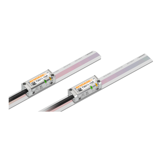
- Page 1 Installation guide M-6688-9046-03-A TONiC FS T3x1x RELM20 / RSLM20 high-accuracy linear encoder ™ system Functional Safety installation guide and safety manual www.renishaw.com/tonicdownloads #renishaw...
- Page 2 This page is intentionally left blank. TONiC™ FS RELM20/ RSLM20 Functional Safety installation guide and safety manual Original instructions...
-
Page 3: Table Of Contents
Readhead mounting and alignment ....................38 Original instructions www.renishaw.com... - Page 4 Diagnostic LEDs ........................40 System calibration .
-
Page 5: Legal Notices
Renishaw office. 47 CFR Section 15.19 Renishaw warrants its equipment and software for a limited period (as set out in the Standard This device complies with part 15 of the FCC Rules. Operation is subject to the following two... - Page 6 The TONiC encoder system is designed to measure position and provide that information to a Outer box drive or controller in applications requiring motion control. It must be installed, operated, and Polypropylene Recyclable maintained as specified in Renishaw documentation and in accordance with the Standard Terms Low density polyethylene foam LDPE Recyclable Inserts and Conditions of the Warranty and all other relevant legal requirements.
- Page 7 Disposal of waste electrical and electronic equipment The use of this symbol on Renishaw products and/or accompanying documentation indicates that the product should not be mixed with general household waste upon disposal. It is the responsibility of the end user to dispose of this product at a designated collection point for waste electrical and electronic equipment (WEEE) to enable reuse or recycling.
- Page 8 Renishaw and the United States Government, civilian federal agency or prime contractor respectively. Please consult the applicable contract or •...
-
Page 9: Definitions
System manufacturer Personnel with responsibility for selecting the encoder and verifying its capability is appropriate for the safety related application. System installer Personnel with responsibility for fitting the encoder in the specific application. Original instructions www.renishaw.com... -
Page 10: Information For Use
Information for use WARNING System components covered by this installation guide: Not to be used in environments where there is an explosive atmosphere WARNING Not to be used by medical devices The TONiC FS system comprises of the following parts: The TONiC FS system is designed to be used as part of a safety-related control system as •... -
Page 11: Functional Safety Data Declaration
Systematic capability Demand mode Continuous ISO 13849 safety data TONiC FS readhead TONiC FS readhead TONiC FS readhead and Ti interface and DOP interface MTTF (years) 1300 Diagnostic coverage Medium (90%) Category Performance level Lifetime /Replacement limits 20 years Original instructions www.renishaw.com... -
Page 12: Safety Sub-Functions
Safety sub-functions The TONiC Functional Safety (FS) encoder system provides safe position data that supports the following safety sub-functions defined by IEC 61800-5-2: • Safe stop 1 (SS1) and Safe stop 2 (SS2) • Safe operating stop (SOS) • Safe limited acceleration (SLA) ≤ 500 m/s •... -
Page 13: Safety Function
FMEDA. NOTE: For the purposes of the FMEDA calculation the following conditions have been assumed: Method SN29500-2005-1 Environment Ground mobile Temperature 85 °C Original instructions www.renishaw.com... - Page 14 Installation Evaluation unit monitoring For the safety function to be valid the instructions detailed in this installation guide must be To achieve full system integrity the evaluation unit must continuously monitor the analogue followed. The information relating to all scale types and mounting options is listed. The builder/ outputs and, in the case of fault detection, place the system into a safe state within the process installer/maintainer/ repairer must apply the instructions for the product being installed as defined safety time.
- Page 15 DO operate between 0 °C and +70 °C When cleaning the system: DO use Renishaw (A-9523-4040) alcohol wetted scale wipes to clean the readhead optics and scale, available from your local Renishaw representative. Or use a clean, dry, lint-free cloth.
- Page 16 ‘Commissioning test’ on page 14. It is advisable that, in the event of failure, the affected parts should be returned to Renishaw for further analysis. Using damaged parts invalidates the Functional Safety certification. Proof testing It is the responsibility of the system manufacturer to define any proof testing of the system.
-
Page 17: Certification
Under the terms of CSA SIRA Functional Safety Certificate SIRA CASS00023/02, for the management and self-certification of functional safety activities up to SIL3/PLd: Renishaw plc declares that the products shown by this installation guide meet the requirements of: IEC 61508-1:2010, IEC 61508-2:2010 and IEC 61508-3:2010... -
Page 18: Declaration Of Conformity
For the full declaration of conformity EUD2021-00817 see www.renishaw.com/productcompliance. EU based person authorised to compile the technical file: - Renishaw (Ireland) DAC, Swords Business Park, Swords, Co. Dublin, K67 FX67, Ireland. TONiC™ FS RELM20/ RSLM20 Functional Safety installation guide and safety manual... - Page 19 Summary of the UK declaration of conformity UKD2021-00817 This declaration of conformity is issued under the sole responsibility of the manufacturer, Renishaw plc. The object of the declaration is identified below: - Product name: TONiC Functional Safety (FS) encoder system Description: Revision of TONiC, to comply with the requirements of Functional Safety.
-
Page 20: Storage And Handling
Storage and handling TONiC non-contact optical encoder systems provide good immunity against contaminants such as dust, fingerprints and light oils. However, in harsh environments such as machine tool applications, protection should be provided to prevent ingress of coolant or oil. Minimum bend radius RELM20 - DO NOT BEND RSLM20 - 250 mm... - Page 21 Original instructions www.renishaw.com...
- Page 22 Temperature Storage System −20 °C to +70 °C Operating System 0 °C to +70 °C Humidity 95% relative humidity (non-condensing) to IEC 60068-2-78 TONiC™ FS RELM20/ RSLM20 Functional Safety installation guide and safety manual Original instructions...
-
Page 23: Tonic T3X1X Readhead Installation Drawing
The dynamic bend radius is not applicable for UHV cables. UHV cables are for static use only. The UHV cable diameter is approximately 3 mm. The recommended thread engagement is 5 mm minimum (7.5 mm including counterbore) and the recommended tightening torque is 0.25 Nm to 0.4 Nm. Original instructions www.renishaw.com... -
Page 24: Ti Interface Drawing
Ti interface drawing Dimensions and tolerances in mm 6 minimum R > 20 dynamic bend radius R > 10 static bend radius CAL/AGC push button switch access hole Ø2.4 33.3 Cover plate 4- 40 UNC × 2 CAL button operation Function Operation Calibration (CAL) routine enable /disable Push and release (< 3 seconds) Automatic Gain Control (AGC) enable/ disable Push and release (> 3 seconds) -
Page 25: Dop Interface Drawing
Output 26-way Calibration button high-density D-type plug Set-up LED PORT NOT CONNECTED 33.3 Cable exit 12.4 2.8 (0.11 inch) External earthing tag Mounting for 35 mm DIN rail (EN 50022) Access hatch for readhead cable connection 14.2 37.3 93.5 Original instructions www.renishaw.com... -
Page 26: Relx20/Rslx20 Measuring Lengths
RELx20/RSLx20 measuring lengths Dimensions and tolerances in mm Measuring length, ML = (L − 25) with dual 10 mm limits ML = (L − 10) without limits 0.05 F = axis of motion Ra 3.2 2.1 ±0.15 Optical centreline Limit sensor position (incremental and reference mark) TONiC™... -
Page 27: Relx20 Installation Drawing
When scale is to be mounted horizontally on a vertical surface, position the dowels so that the datum edge is supported. Double-sided adhesive tape is included with all scale lengths. Original instructions www.renishaw.com... -
Page 28: Rslx20 Installation Drawings
RSLx20 installation drawings Dimensions and tolerances in mm Datum edge 0.05/50 Alignment dowels, maximum spacing 350 14.9 ±0.2 F = axis of motion RSLM20 (Centre reference mark) Use with T3011 readhead L < 4 m: L/2 ±0.5 L ≥ 4 m: L/2 ±2 Reference mark position Scale length (L) RSLE20... -
Page 29: Equipment Required For Adhesive Mounting The Relx20/Rslx20 Spar Scale
Appropriate cleaning solvents (see ‘Storage and handling’ on page 20) • Pencil or other appropriate marker • Scissors Optional parts: • Renishaw scale wipes (A-9523-4040) • Lint-free cloth • Reference mark selector magnet (A-9653-0143) • Q limit magnet (A-9653-0139) •... -
Page 30: Installing The Adhesive Mounted Relx20/Rslx20 Scale
Installing the adhesive mounted RELx20/RSLx20 scale 1. Thoroughly clean and degrease the substrate with a lint-free cloth and clean the underside of 3. Remove the backing liner from one side of the adhesive tape and stick it to the underside of the scale using approved solvents (see ‘Storage and handling’... - Page 31 6. Remove any excess epoxy with firm finger pressure. Excess epoxy 7. Allow 24 hours for the epoxy to cure fully and then clean the scale using Renishaw scale wipes or a clean, dry, lint-free cloth. Support dowels Mounting ledge Original instructions www.renishaw.com...
-
Page 32: Reference Mark Selector And Limit Magnet Installation
Reference mark selector and limit magnet installation IMPORTANT: Allow 24 hours after the scale application before fitting the magnets. Magnet applicator tool For accuracy and ease of positioning of the reference mark selector and limit magnets, the applicator tool should be used. The magnet should be attached to the applicator tool as shown. Limit magnets can be positioned at any user defined location along the scale, but the reference mark selector magnet (T3010 readheads only) should be positioned adjacent to the selected IN-TRAC reference mark as shown. -
Page 33: Tonic Quick-Start Guide
LED on the readhead switches on. Calibration (CAL) values and AGC status are stored in readhead non-volatile memory at power down. NOTE: If calibration fails, restore factory defaults (see ‘Restoring factory defaults’ on page 42). Then repeat the installation and calibration routine. Original instructions www.renishaw.com... -
Page 34: Cable Connection
Route the cable away from operating environments that will exceed the EMC limits defined in IEC 61800-5-2: Annex E second environment. • Use only Renishaw approved cables between the readhead and the interface. • The customer is responsible for verifying the product function where the cable has been re-terminated, including the installation of extension cables. -
Page 35: System Connection - Ti Interface
Connecting the readhead 8. Remove the cover plate as shown (2 × M2.5 hex head screws). 9. Taking care not to touch the pins, plug the connector into the socket in the interface, ensuring correct orientation as shown. Original instructions www.renishaw.com... - Page 36 5. Refit the cover plate ensuring the cable ferrule is located in the recess on the inside and no wires are trapped under the cover plate. Disconnecting the readhead 1. Remove the cover plate on the interface (2 × M2.5 hex head screws). 2.
-
Page 37: System Connection - Dop Interface
2. Gently lever the connector PCB (on the end of the cable) out of the socket. Do not pull the cable to remove the connector. 3. Place the connector in an anti-static bag. 4. Refit the cover plate. Original instructions www.renishaw.com... -
Page 38: Readhead Mounting And Alignment
Readhead mounting and alignment Mounting brackets The bracket must have a flat mounting surface and should provide adjustment to enable conformance to the installation tolerances, allow adjustment to the rideheight of the readhead, and be sufficiently stiff to prevent deflection or vibration of the readhead during operation. NOTES: •... - Page 39 (CAL LED off). When reinstalling the readhead the factory defaults should be Pitch restored (see ‘Restoring factory defaults’ on page 42). Roll 0° ±1° 0° ±0.5° Green spacer Rideheight 2.1 ±0.15 mm DOP interface set-up LED status Blue or Green Orange purple Original instructions www.renishaw.com...
-
Page 40: Diagnostic Leds
Alarm output will take the form of 3-state or line driven E signal depending on interface configuration. Also, some configurations do not output overspeed alarm. See TONiC FS encoder system data ™ sheet (Renishaw part no. L-9517-9878) for details of interface configuration. • Momentary alarm output status only, while fault condition remains. -
Page 41: System Calibration
1. Press and release the CAL button on the end of the interface (for < 2 seconds) using a 2 mm allen key or similar tool. WARNING: Activating the CAL switch only requires 2.5 N force. Applying excess force may permanently damage the switch. Ti interface DOP interface Original instructions www.renishaw.com... -
Page 42: Restoring Factory Defaults
Restoring factory defaults Reference mark phasing 1. Move the readhead back and forth over the selected reference mark until the CAL LED stops When realigning the readhead, reinstalling the system, or in the case of continued calibration flashing and remains off. The reference mark is now phased. failure, factory defaults must be restored. -
Page 43: Output Signals
Limits Open collector Inner shield Green / Yellow Shield Outer shield Outer screen Set-up Calibrate Inner shield Not connected Shield Outer shield Case Ti0000 interface output connector: 15-way D-type plug There is no inner shield on UHV cables. Original instructions www.renishaw.com... - Page 44 DOP interface output Function Output type Signal 5 V Power 5 V Sense Power 0 V Power 0 V Sense − RS422A digital − Incremental signals Cosine − Analogue Sine − RS422A digital − Reference mark Analogue − Alarm RS422A digital −...
-
Page 45: Speed
0.0065 4.50 2.25 0.90 0.450 0.225 0.090 0.045 0.023 0.009 0.0045 3.37 1.68 0.67 0.338 0.169 0.068 0.034 0.017 0.0068 0.0034 0.84 0.42 0.16 0.084 0.042 0.017 0.008 0.004 0.0017 0.0008 Analogue output 10 (−3dB) (Ti0000 and DOP) Original instructions www.renishaw.com... -
Page 46: Electrical Connections
The maximum cable length between the readhead and the interface is 10 m • The maximum extension cable is dependent on the cable type, the readhead cable length and the clock speed. Contact your local Renishaw representative for more information. •... - Page 47 The maximum cable length between the readhead and the interface is 10 m • The maximum extension cable is dependent on the cable type, the readhead cable length and the clock speed. Contact your local Renishaw representative for more information. •...
- Page 48 Recommended signal termination Analogue outputs Digtial outputs (DOP only) 120R Readhead Customer 220 pF electronics A B Z E+ − 120R Cable Z = 120R Limit outputs 5 to 24 V A B Z E− 220 pF Standard RS422A line receiver circuitry. The capacitors are recommended for improved noise immunity.
-
Page 49: Ti Interface Output Specifications
0.8 to 1.2 Vpp 45° Length of limit actuator +) − (V −) 360° (nominal) The reference output is bi-directionally repeatable. The differential pulse V is centred on 45°. Only the analogue sine and cosine outputs are functionally safe. Original instructions www.renishaw.com... - Page 50 Ti interface set-up 3.3 (nom) Voltage at V Signal level Between 50% and 70% the signal level V is a duty cycle. Time spent at 3.3 V increases with incremental signal level. At > 70% the signal level V is nominal 3.3 V. The set-up signal as shown is not present during the calibration routine.
-
Page 51: Dop Interface Output Specifications
NOTE: Select ‘standard’ or ‘wide’ reference at time of ordering, to match the requirements of the controller being used. Only the analogue sine and cosine outputs are functionally safe. For clarity, the inverse signals are not shown. Original instructions www.renishaw.com... - Page 52 Limits Alarm Open collector output, asynchronous pulse Line driven (asynchronous pulse) Active high > 15 ms Repeatability < 0.1 mm The line driven alarm is asserted when: Length of limit actuator • The signal amplitude is < 20% or > 135% • The readhead speed is too high for reliable operation or active low or 3-state alarm Repeatability < 0.1 mm...
-
Page 53: General Specifications
50 m (with analogue interface) CAUTION: Renishaw encoder systems have been designed to the relevant EMC standards, but must be correctly integrated to achieve EMC compliance. In particular, attention to the shielding arrangements is essential. For UHV cables ensure that the cable to UHV connector termination meets the EM requirements defined by IEC 61800-5-2: Annex E second environment. -
Page 54: Relx20 Scale Specifications
RELx20 scale specifications Form (height × width) 1.8 mm × 14.9 mm (including adhesive backing tape) Pitch 20 µm Certified to ±1 μm for lengths up to 1 m Accuracy (at 20 °C) - includes slope ±1 μm/m for lengths > 1 m to 1.5 m and linearity (Calibration traceable to International Standards) Supplied lengths... -
Page 55: Reference Mark
The limit output is nominally asserted when the readhead limit switch sensor passes the limit magnet leading edge, but can trigger up to 3 mm Trigger point before that edge Mounting Self-adhesive backing tape. Customer placed at desired locations Repeatability < 0.1 mm When using a T1030 readhead, a self-adhesive reference mark selector magnet is required to choose the reference mark that is output. Original instructions www.renishaw.com... - Page 56 +44 (0) 1453 524524 uk@renishaw.com © 2019–2023 Renishaw plc. All rights reserved. This document may not be copied or reproduced in whole or in part, or transferred to any other WHILE CONSIDERABLE EFFORT WAS MADE TO VERIFY THE ACCURACY OF THIS media or language by any means, without the prior written permission of Renishaw.
Need help?
Do you have a question about the TONiC FS T3 1 Series and is the answer not in the manual?
Questions and answers