
Related Manuals for Renishaw TONiC T103x RKLC20-S


Summary of Contents for Renishaw TONiC T103x RKLC20-S
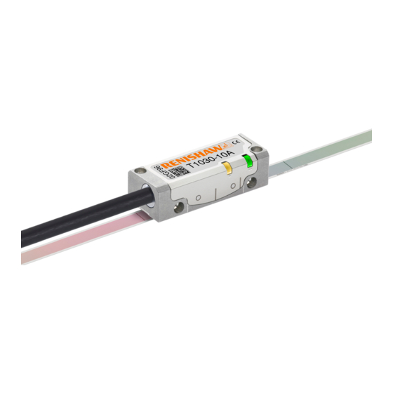
- Page 1 Installation guide M-9653-9568-02-A TONiC RSLM high accuracy linear encoder T103x RKLC20-S linear encoder system ™...
-
Page 2: Table Of Contents
Contents Legal notices Storage and handling TONiC T103x readhead installation drawing Ti interface drawing RKLC20-S scale installation drawing RKLC20-S scale application End clamps Reference mark selector and limit magnet installation TONiC quick-start guide System connection Readhead mounting and alignment System calibration Restoring factory defaults Switching Automatic Gain Control (AGC) on or off Output signals... -
Page 3: Legal Notices
Renishaw. including interference that may cause undesired operation. The user is cautioned that any changes or modifications not expressly approved by Renishaw plc or authorised Trade marks representative could void the user’s authority to operate the equipment. -
Page 4: Storage And Handling
Storage and handling Minimum bend radius RKLC20-S – 50 mm NOTE: During storage, ensure self-adhesive tape is on the outside of bend. Scale and readhead Readhead only N-heptane Acetone Storage Installation Operating Humidity +70 °C +35 °C +70 °C −20 °C +10 °C 0 °C Chlorinated COCH Solvents Propan-2-ol... -
Page 5: Tonic T103X Readhead Installation Drawing
TONiC T103x readhead installation drawing Dimensions and tolerances in mm 2 off holes M2.5 through, counterbored Ø3 × 2.75 deep Forward direction of from alternative mounting face readhead relative to scale (Yaw tol. ±0.4°) Reference mark 0.25 (Roll tol. ±0.5°) 8.75 * Offset 3.75 ±0.5 selector magnet... -
Page 6: Ti Interface Drawing
Ti interface drawing Dimensions and tolerances in mm 6 min R > 20 Dynamic bend radius R > 10 Static bend radius CAL/AGC push button switch access hole Ø2.4 33.3 Diagnostic LED (Ti0004 - Ti20KD and TD4000 - TD0040) Cover plate 4-40 UNC x 2 CAL button operation Push and release (< 3 seconds) ‑... -
Page 7: Rklc20-S Scale Installation Drawing
RKLC20-S scale installation drawing Dimensions and tolerances in mm Overall length (L + 30) Scale length (L) Measuring length ML = (L − 40) (ML = (L − 55) with dual limits) (20 when Q limit Readhead optical detector position at extent of travel not used) TONiC readhead Reference mark selector magnet... -
Page 8: Rklc20-S Scale Application
Suitable for: RKLC20 tape scale (any length) Required parts: Optional parts: Renishaw scale wipes (A-9523-4040) Appropriate length of RKLC20-S scale ('RKLC20-S scale installation drawing', page 5) Scale applicator - side mounted (A-6547-1912) or top mounted (A-6547-1915) Lint-free cloth End clamp kit (A-9523-4015) - Page 9 RKLC20-S scale application (continued) Cutting scale If required cut scale to length using guillotine or shears. Using the guillotine Using the shears The guillotine should be held securely in place, using a suitable vice or clamping method. Feed the RKLC20‑S scale through the first apperture on the shears (as shown). Once secured, feed the RKLC20-S scale through the guillotine as shown, and place guillotine press block down onto the scale.
- Page 10 Remove applicator carefully. Apply firm finger pressure via a clean lint‑free cloth along the length of the scale after application to ensure complete adhesion. Clean the scale using Renishaw scale wipes or a clean, dry, lint-free cloth. Fit end clamps ('End clamps', page NOTE: Scale applicator can be mounted either way round to enable easiest orientation for scale installation.
-
Page 11: End Clamps
End clamps The end clamp kit is designed to be used with Renishaw RKLC20‑S scale. Alternative, narrow 6 mm wide end clamps (A‑9523‑4111), are also available. NOTE: End clamps can be mounted before or after readhead installation. The end clamp features two small regions of contact adhesive. These will temporarily hold the end Clean ends of scale and the area where end clamps are to be fitted using Renishaw scale wipes clamp in position while the adhesive cures. -
Page 12: Reference Mark Selector And Limit Magnet Installation
For more information refer to TONiC encoder system Data sheet ™ (Renishaw part no. L-9517-9337). External magnetic fields greater than 6 mT, in the vicinity of the readhead, may cause false activation of the limit and reference sensors. TONiC RKLC20-S linear installation guide... -
Page 13: Tonic Quick-Start Guide
TONiC quick-start guide This section is a quick-start guide to installing a TONiC system. More detailed information on installing the system is contained on page page page 14 page 15 of this installation guide. INSTALLATION Ensure scale, readhead optical window and mounting faces are clean and free from obstructions. If required, ensure reference mark selector magnet is correctly positioned ('RKLC20-S scale installation drawing', page Plug the readhead cable into the Ti / TD interface under the cover plate and reassemble interface. -
Page 14: System Connection
System connection Approved ESD precautions must be followed at all times during readhead and interface electrical connections. The readhead is connected to the Disconnecting the readhead Ti/TD interface via a small, rugged connector to allow for easy feed-through during installation. Remove the cover plate on the interface Connecting the readhead (2 x M2.5 hex head screws). -
Page 15: Readhead Mounting And Alignment
Momentary status only, while fault condition remains. • Alarm may result in axis position error, re-datum to continue. See the TONiC encoder system Data sheet (Renishaw part no. L‑9517‑9337) for interface configuration details. www.renishaw.com/tonicdownloads This can be downloaded from our website at and is also available from your local Renishaw representative. -
Page 16: System Calibration
System calibration Calibration is an essential operation that completes readhead set-up, with the optimum incremental and reference mark signal settings stored in the readhead’s non-volatile memory. Before system calibration: Clean the scale and readhead optical window (contamination around the reference mark may result in reference mark dephasing). If reinstalling, restore factory defaults ('Restoring factory defaults', page 15). -
Page 17: Restoring Factory Defaults
Restoring factory defaults When realigning the readhead, reinstalling the system, or in the case of continued calibration failure, factory defaults should be restored. To restore factory defaults: Switch system off. Press and hold the CAL button whilst switching the system on. The CAL LED on the readhead will flash several times, indicating that the factory defaults have been restored. Release CAL button. -
Page 18: Output Signals
Output signals Interface Interface output (analogue) Ti0000 only Interface output (digital) Ti0004 to Ti20KD and TD4000 to TD0040 Interface Ti0000 Ti0004 - Ti20KD TD4000 - TD0040 Function Output type Signal Function Output type Signal Power 7, 8 7, 8 Power 5 V Power 2, 9 2, 9... -
Page 19: Speed
Speed Maximum speed (m/s) Clocked output Ti0004 Ti0020 Ti0040 Ti0100 Ti0200 Ti0400 Ti1000 Ti2000 Ti4000 Ti10KD Ti20KD option (MHz) 5 µm 1 µm 0.5 µm 0.2 µm 0.1 µm 50 nm 20 nm 10 nm 5 nm 2 nm 1 nm 6.48 3.24 1.62... -
Page 20: Electrical Connections
Electrical connections Grounding and shielding Recommended signal termination Extension cable Digital outputs Customer maximum 50 m electronics dependent upon Ti / TD interface Readhead clocked output option Customer Inner shield 220 pF electronics A B Z E+ Output signals Cable Z = 120R 120R Outer shield... -
Page 21: Output Specifications
Output specifications Digital output signals Form – Square wave differential line driver to EIA RS422A (except limits P and Q) Incremental* 2 channels A and B in quadrature (90° phase shifted) Alarm Line driven* (Asynchronous pulse) Signal period > 15 ms Resolution Alarm asserted when: –... - Page 22 Output specifications (continued) Analogue output signals Set-up * Incremental 2 channels V and V differential sinusoids in quadrature centred on 1.65 V (90° phase shifted) 3.3 (nom) 20 µm 0.7 to 1.35 Vpp with Green Voltage at V +) −(V −) LED indication, (readhead) and 120R termination.
-
Page 23: General Specifications
40 to 50 < 40 Analogue CAUTION: Renishaw encoder systems have been designed to the relevant EMC standards, but must be correctly integrated to achieve EMC compliance. In particular, attention to shielding arrangements is essential. * To limit maximum tension in the scale (CTE −... -
Page 24: Rklc20-S Scale Specifications
RKLC20-S scale specifications Form 0.15 mm × 6 mm including adhesive (H × W) Pitch 20 µm Accuracy ±5 µm/m (at 20 °C) Linearity ±2.5 µm/m achievable with two point error correction Supplied length 20 mm up to 20 m (> 20 m on request) Material Hardened and tempered martensitic stainless steel fitted with a self‑adhesive backing tape Mass... - Page 25 New Mills, Wotton-under-Edge uk@renishaw.com Gloucestershire, GL12 8JR www.renishaw.com United Kingdom For worldwide contact details, visit www.renishaw.com/contact *M-9653-9568-02* Renishaw plc. Registered in England and Wales. Company no: 1106260. Registered office: New Mills, Wotton-under-Edge, Gloucestershire, GL12 8JR, UK. Part no.: M-9653-9568-02-A Issued: 01.2021...
Need help?
Do you have a question about the TONiC T103x RKLC20-S and is the answer not in the manual?
Questions and answers