
Related Manuals for Renishaw TONiC FS T4 1 Series


Summary of Contents for Renishaw TONiC FS T4 1 Series
- Page 1 Installation guide M-6688-9043-03-A TONiC FS T4xx1 RESM20 angle encoder system ™ Functional Safety installation guide and safety manual www.renishaw.com/tonicdownloads #renishaw...
- Page 2 This page is intentionally left blank. TONiC™ FS RESM20 Functional Safety installation guide and safety manual Original instructions...
-
Page 3: Table Of Contents
System connection - Ti interface .....................41 Original instructions www.renishaw.com... - Page 4 System connection - DOP interface ....................43 T4xx1 readhead and RESM20 compatibility .
-
Page 5: Legal Notices
RADIO FREQUENCY DEVICES such equipment and/or software, or available on request from your local Renishaw office. Renishaw warrants its equipment and software for a limited period (as set out in the Standard 47 CFR Section 15.19 Terms and Conditions), provided that they are installed and used exactly as defined in associated Renishaw documentation. - Page 6 The TONiC encoder system is designed to measure position and provide that information to a Outer box drive or controller in applications requiring motion control. It must be installed, operated, and Polypropylene Recyclable maintained as specified in Renishaw documentation and in accordance with the Standard Terms Low density polyethylene foam LDPE Recyclable Inserts and Conditions of the Warranty and all other relevant legal requirements.
- Page 7 Disposal of waste electrical and electronic equipment The use of this symbol on Renishaw products and/or accompanying documentation indicates that the product should not be mixed with general household waste upon disposal. It is the responsibility of the end user to dispose of this product at a designated collection point for waste electrical and electronic equipment (WEEE) to enable reuse or recycling.
- Page 8 Renishaw and the United States Government, civilian federal agency or prime contractor respectively. Please consult the applicable contract or •...
-
Page 9: Definitions
System manufacturer Personnel with responsibility for selecting the encoder and verifying its capability is appropriate for the safety related application. System installer Personnel with responsibility for fitting the encoder in the specific application. Original instructions www.renishaw.com... -
Page 10: Information For Use
Information for use WARNING System components covered by this installation guide: Not to be used in environments where there is an explosive atmosphere WARNING Not to be used by medical devices The TONiC FS system comprises of the following parts: The TONiC FS system is designed to be used as part of a safety-related control system as •... -
Page 11: Functional Safety Data Declaration
Systematic capability Demand mode Continuous ISO 13849 safety data TONiC FS readhead TONiC FS readhead TONiC FS readhead and Ti interface and DOP interface MTTF (years) 1300 Diagnostic coverage Medium (90%) Category Performance level Lifetime /Replacement limits 20 years Original instructions www.renishaw.com... -
Page 12: Safety Sub-Functions
Safety sub-functions The TONiC Functional Safety (FS) encoder system provides safe position data that supports the following safety sub-functions defined by IEC 61800-5-2: • Safe stop 1 (SS1) and Safe stop 2 (SS2) • Safe operating stop (SOS) • Safe limited acceleration (SLA) ≤ 500 m/s •... -
Page 13: Safety Function
FMEDA. NOTE: For the purposes of the FMEDA calculation the following conditions have been assumed: Method SN29500-2005-1 Environment Ground mobile Temperature 85 °C Original instructions www.renishaw.com... - Page 14 Installation Evaluation unit monitoring For the safety function to be valid the instructions detailed in this installation guide must be To achieve full system integrity the evaluation unit must continuously monitor the analogue followed. The information relating to all scale types and mounting options is listed. The builder/ outputs and, in the case of fault detection, place the system into a safe state within the process installer/maintainer/ repairer must apply the instructions for the product being installed as defined safety time.
- Page 15 DO operate between 0 °C and +70 °C ring settings. When cleaning the system: DO use Renishaw (A-9523-4040) alcohol wetted scale wipes to clean the readhead optics and scale, available from your local Renishaw representative. Or use a clean, dry, lint-free cloth.
- Page 16 ‘Commissioning test’ on page 14. It is advisable that, in the event of failure, the affected parts should be returned to Renishaw for further analysis. Using damaged parts invalidates the Functional Safety certification. Proof testing It is the responsibility of the system manufacturer to define any proof testing of the system.
-
Page 17: Certification
Under the terms of CSA SIRA Functional Safety Certificate SIRA CASS00023/02, for the management and self-certification of functional safety activities up to SIL3/PLd: Renishaw plc declares that the products shown by this installation guide meet the requirements of: IEC 61508-1:2010, IEC 61508-2:2010 and IEC 61508-3:2010... -
Page 18: Declaration Of Conformity
For the full declaration of conformity EUD2021-00817 see www.renishaw.com/productcompliance. EU based person authorised to compile the technical file: - Renishaw (Ireland) DAC, Swords Business Park, Swords, Co. Dublin, K67 FX67, Ireland. TONiC™ FS RESM20 Functional Safety installation guide and safety manual... - Page 19 Summary of the UK declaration of conformity UKD2021-00817 This declaration of conformity is issued under the sole responsibility of the manufacturer, Renishaw plc. The object of the declaration is identified below: - Product name: TONiC Functional Safety (FS) encoder system Description: Revision of TONiC, to comply with the requirements of Functional Safety.
-
Page 20: Storage And Handling
Storage and handling TONiC non-contact optical encoder systems provide good immunity against contaminants such as dust, fingerprints and light oils. However, in harsh environments such as machine tool applications, protection should be provided to prevent ingress of coolant or oil. System Ring only Readhead only... - Page 21 Original instructions www.renishaw.com...
- Page 22 Temperature Storage System −20 °C to +70 °C Operating System 0 °C to +70 °C Humidity 95% relative humidity (non-condensing) to IEC 60068-2-78 TONiC™ FS RESM20 Functional Safety installation guide and safety manual Original instructions...
-
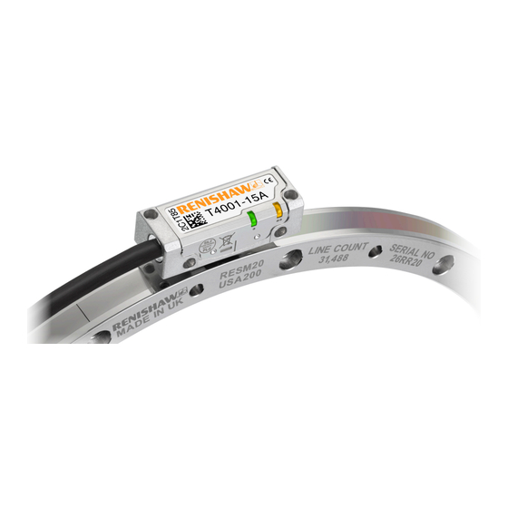
Page 23: Tonic T4Xx1 Readhead Installation Drawing
The recommended thread engagement is 5 mm minimum (7.5 mm including counterbore) and the recommended tightening torque is 0.25 Nm to 0.4 Nm. The dynamic bend radius is not applicable for UHV cables. UHV cables are for static use only. The UHV cable diameter is approximately 3 mm. Original instructions www.renishaw.com... -
Page 24: Ti Interface Drawing
Ti interface drawing Dimensions and tolerances in mm 6 minimum R > 20 dynamic bend radius R > 10 static bend radius CAL/AGC push button switch access hole Ø2.4 33.3 Cover plate 4- 40 UNC × 2 CAL button operation Function Operation Calibration (CAL) routine enable /disable Push and release (< 3 seconds) Automatic Gain Control (AGC) enable/ disable Push and release (> 3 seconds) -
Page 25: Dop Interface Drawing
Output 26-way Calibration button high-density D-type plug Set-up LED PORT NOT CONNECTED 33.3 Cable exit 12.4 2.8 (0.11 inch) External earthing tag Mounting for 35 mm DIN rail (EN 50022) Access hatch for readhead cable connection 14.2 37.3 93.5 Original instructions www.renishaw.com... -
Page 26: Resm20 Ring Specifications
RESM20 ring specifications Pitch 20 μm Material 303 /304 stainless steel Coefficient of thermal expansion (CTE) at 20 °C 15.5 ±0.5 μm/m/°C The ring must be installed and operated with the following specifications. Mounting shaft coefficient of thermal expansion at 20 °C 15.5 ±0.5 μm/m/°C Installation temperature 20 ±5 °C... -
Page 27: Resm20 'A' Section Ring Installation Drawing
θ The angle between two clearance holes is 2 ØDI ØDH ØDO The dimensions DO, DI and DH for the RESM20 ‘A’ section rings are listed on the following page. Original instructions www.renishaw.com... - Page 28 RESM20 ‘A’ section ring dimensions Nominal Mounting holes Nominal Mounting holes external Line Readhead external Line Readhead diameter count (mm) (mm) model diameter count (mm) (mm) model θ θ (mm) (mm) (mm) (mm) 52.20 30.04 200.40 180.04 31 488 15° 8 192 30°...
-
Page 29: Resm20 'B' Section Ring Installation Drawing
The angle θ between two clearance holes is 2 Ø DO The dimensions DO, DI and DH for the RESM20 ‘B’ section rings are listed on the following page. Original instructions www.renishaw.com... - Page 30 RESM20 ‘B’ section ring dimensions Mounting holes Nominal external Line diameter Readhead model count (mm) (mm) θ (mm) (mm) 52.20 32.04 8 192 30° 52.10 32.00 T4x21 57.35 37.04 9 000 30° 57.25 37.00 75.40 55.04 11 840 30° 75.30 55.00 100.30 80.04...
-
Page 31: Resm20 Ring Mounting Options
• Will not correct eccentricity of the supporting shaft. • Offers highest accuracy. Notes • Enables eccentricity to be compensated. • Offers excellent mechanical stability against thermal cycling, shock and vibration. • Minimises cost of substrate preparation. Original instructions www.renishaw.com... -
Page 32: Equipment Required For Taper Mounting The Resm20 'A' Section Ring
Dial Test Indicator (DTI) • Appropriate cleaning solvents (see ‘Storage and handling’ on page 20) • Hex key • Torque wrench Optional parts: • Renishaw scale wipes (A-9523-4040) • Lint-free cloth TONiC™ FS RESM20 Functional Safety installation guide and safety manual Original instructions... -
Page 33: Resm20 'A' Section Ring Taper Mounting
83.65 155.65 212.65 383.65 DO = Nominal external diameter. Recommended surface finish ≤ Ra 1.2. NOTE: It is recommended that the mounting surface is a turned, rather than ground finish. Allow 2 mm for 417 mm, 489 mm and 550 mm rings only. Original instructions www.renishaw.com... - Page 34 • Remove the protective film from the surface of the RESM20 ring. • Clean shaft taper and internal taper of RESM20 as recommended in ‘Storage and handling’ on page 20. Step 1 • Insert the first screws • For RESM20 rings with 6, 9 or 18 mounting holes, use 3 equally-spaced M3 screws. •...
- Page 35 As described in Step 1, adjust all the screws already inserted, so that the radial displacement at each screw location is within ±5 µm. • Again, at this stage, the screws should only be lightly tightened (less than 0.5 Nm). NOTE: The torque required to achieve the radial displacement tolerance may be slightly higher during step 2 than during step 1. Original instructions www.renishaw.com...
- Page 36 Repeat this process until the radial displacement at all of the screw locations is within ±3 µm and that all screw torques are within the specified range. • Excessive tightening of screws can have a small effect on accuracy. Contact your local Renishaw representative for more details. •...
-
Page 37: Equipment For Interference Fit Mounting The Resm20 'A' Section And Resm20 'B' Section Rings
NOTE: Recommended screw type M3 × 0.5 and must comply with ISO 4762/DIN 912 grade 10.9 minimum/ANSI B18.3.1M with a CTE of 10 to 16 µm/m/°C @ 20 °C. • Appropriate cleaning solvents (see ‘Storage and handling’ on page 20) • Hex key • Torque wrench Optional parts: • Renishaw scale wipes (A-9523-4040) • Lint-free cloth Original instructions www.renishaw.com... -
Page 38: Resm20 'A' Section And Resm20 'B' Section Ring Interference Fit Mounting
209.060 • Insert screws into all mounting holes. 80.023 209.031 • Tighten all screws. 95.045 235.060 • Clean ring using Renishaw scale cleaning wipes or a clean, dry, lint-free cloth. 95.023 235.031 104.045 280.066 NOTES: 104.023 280.034 130.052 330.073 •... -
Page 39: Tonic Quick-Start Guide
LED on the readhead switches on. Calibration (CAL) values and AGC status are stored in readhead non-volatile memory at power down. NOTE: If calibration fails, restore factory defaults (see ‘Restoring factory defaults’ on page 49). Then repeat the installation and calibration routine. Original instructions www.renishaw.com... -
Page 40: Cable Connection
Route the cable away from operating environments that will exceed the EMC limits defined in IEC 61800-5-2: Annex E second environment. • Use only Renishaw approved cables between the readhead and the interface. • The customer is responsible for verifying the product function where the cable has been re-terminated, including the installation of extension cables. -
Page 41: System Connection - Ti Interface
Connecting the readhead 1. Remove the cover plate as shown (2 × M2.5 hex head screws). 2. Taking care not to touch the pins, plug the connector into the socket in the interface, ensuring correct orientation as shown. Original instructions www.renishaw.com... - Page 42 5. Refit the cover plate ensuring the cable ferrule is located in the recess on the inside and no wires are trapped under the cover plate. Disconnecting the readhead 1. Remove the cover plate on the interface (2 × M2.5 hex head screws). 2.
-
Page 43: System Connection - Dop Interface
2. Gently lever the connector PCB (on the end of the cable) out of the socket. Do not pull the cable to remove the connector. 3. Place the connector in an anti-static bag. 4. Refit the cover plate. Original instructions www.renishaw.com... -
Page 44: T4Xx1 Readhead And Resm20 Compatibility
Reference mark position The IN-TRAC ™ reference mark is integrated in the scale, radially aligned with the centre of the mounting hole to the left of the ‘Renishaw’ logo within ±0.5 mm. No external actuators or physical adjustment are required. -
Page 45: Readhead Mounting And Alignment
No washer is required under the screw head. • The minimum thread engagement is 5 mm (7.5 mm including counterbore). • The tightening torque should be between 0.25 Nm and 0.4 Nm. • The mounting hole clearance will contribute to mechanical safe position. Original instructions www.renishaw.com... - Page 46 Readhead set-up Ensure that the ring, readhead optical window and mounting face are clean and free Readhead set-up LED status from obstructions. NOTE: For full readhead and interface LED diagnostics, see ‘Diagnostic LEDs’ on page 47. NOTES: Green Orange • Ensure that the protective film is removed from the ring before installing the readhead. •...
-
Page 47: Diagnostic Leds
Alarm output will take the form of 3-state or line driven E signal depending on interface configuration. Also, some configurations do not output overspeed alarm. See TONiC FS encoder system data ™ sheet (Renishaw part no. L-9517-9878) for details of interface configuration. • Momentary alarm output status only, while fault condition remains. -
Page 48: System Calibration
System calibration Calibration is an essential operation that completes readhead set-up, with the optimum 2. The CAL LED will now periodically single-flash to indicate that it is in incremental signal calibration mode. incremental and reference mark signal settings stored in the readhead’s non-volatile memory. 3. -
Page 49: Restoring Factory Defaults
LED on the readhead will be illuminated when AGC is active. CAL LED Settings stored Single flashing None, restore factory defaults and recalibrate NOTE: The system must be calibrated before switching AGC on (see ‘System calibration’ Double flashing Incremental only on page 48). Off (auto-complete) Incremental and reference mark Original instructions www.renishaw.com... -
Page 50: Output Signals
P and Q limit actuators are not suitable for ring encoder (RESM) installation. Limit switch signal detail is included here for information only. Please contact your local Renishaw representative if you require limits on your rotary installation. TONiC™ FS RESM20 Functional Safety installation guide and safety manual... - Page 51 P and Q limit actuators are not suitable for ring encoder (RESM) installation. Limit switch signal detail is included here for information only. DOP interface output connector: 26-way Please contact your local Renishaw representative if you require limits on your high-density D-type plug rotary installation. Original instructions...
-
Page 52: Speed
Speed Maximum speed (m/s) Clocked output option DOP0004 DOP0020 DOP0040 DOP0100 DOP0200 DOP0400 DOP1000 DOP2000 DOP4000 DOP10KD DOP20KD (MHz) 5 µm 1 µm 0.5 µm 0.2 µm 0.1 µm 50 nm 20 nm 10 nm 5 nm 2 nm 1 nm 6.48 3.24 1.62 0.648 0.324 0.162 0.0654 0.032 5.40 2.70 1.35 0.540 0.270... -
Page 53: Electrical Connections
The maximum cable length between the readhead and the interface is 10 m • The maximum extension cable is dependent on the cable type, the readhead cable length and the clock speed. Contact your local Renishaw representative for more information. •... - Page 54 The maximum cable length between the readhead and the interface is 10 m • The maximum extension cable is dependent on the cable type, the readhead cable length and the clock speed. Contact your local Renishaw representative for more information. •...
- Page 55 A B Z E+ 120R Cable Z = 120R A B Z E− 220 pF Standard RS422A line receiver circuitry. The capacitors are recommended for improved noise immunity. Only the analogue sine and cosine outputs are functionally safe. Original instructions www.renishaw.com...
-
Page 56: Ti Interface Output Specifications
Ti interface output specifications Analogue signals Incremental Set-up 2 channels V and V differential sinusoids in quadrature centred on ~1.65 V. (90° phase shifted) 20 µm 3.3 (nom) 0.7 to 1.35 Vpp with green Voltage at V LED indication (readhead) +) − (V −) and 120R termination. -
Page 57: Dop Interface Output Specifications
NOTE: Select ‘standard’ or ‘wide’ reference at time of ordering, to match the requirements of the controller being used. Only the analogue sine and cosine outputs are functionally safe. For clarity, the inverse signals are not shown. Original instructions www.renishaw.com... - Page 58 Alarm Line driven (asynchronous pulse) > 15 ms The line driven alarm is asserted when: • The signal amplitude is < 20% or > 135% • The readhead speed is too high for reliable operation or 3-state alarm Differentially transmitted signals are forced open circuit for > 15 ms when the alarm conditions are valid.
-
Page 59: General Specifications
50 m (with analogue interface) CAUTION: Renishaw encoder systems have been designed to the relevant EMC standards, but must be correctly integrated to achieve EMC compliance. In particular, attention to the shielding arrangements is essential. For UHV cables ensure that the cable to UHV connector termination meets the EM requirements defined by IEC 61800-5-2: Annex E second environment. - Page 60 +44 (0) 1453 524524 uk@renishaw.com © 2019–2023 Renishaw plc. All rights reserved. This document may not be copied or reproduced in whole or in part, or transferred to any other WHILE CONSIDERABLE EFFORT WAS MADE TO VERIFY THE ACCURACY OF THIS media or language by any means, without the prior written permission of Renishaw.
Need help?
Do you have a question about the TONiC FS T4 1 Series and is the answer not in the manual?
Questions and answers