
Related Manuals for Renishaw TONiC FS T301 Series


Summary of Contents for Renishaw TONiC FS T301 Series
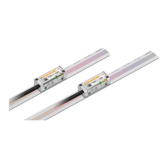
- Page 1 Installation guide M-6688-9046-02-B TONiC FS T301x RSLM20 / RELM20 high accuracy linear encoder system ™ Functional Safety installation guide and safety manual...
-
Page 2: Table Of Contents
Contents Product compliance Readhead mounting and alignment Definitions System calibration Information for use Diagnostic LEDs Functional Safety data declaration Output signals Safety function Speed Certification Electrical connections Storage and handling Output specifications TONiC FS T301 readhead installation drawing General specifications Measuring lengths RSLM20 scale technical specifications Scale installation drawing RELM20 scale technical specifications Scale installation Reference mark... -
Page 3: Product Compliance
Product compliance Patents Features of Renishaw’s encoder systems and similar products are the subjects of the following patents and This document is an installation guide and safety manual, which details the actions required for the safe patent applications: integration of the TONiC FS (Functional Safety) encoder system, as designated by the T3 prefix in the part number, into a functionally safe system;... -
Page 4: Definitions
Definitions Functional Safety data declaration WARNING A hazard with a medium risk of injury if not avoided Product identification TONiC FS (Functional Safety) ESD handling The ESD Susceptibility Symbol consists of a triangle, a reaching hand, and a slash IEC 61508 safety data through the reaching hand. The triangle means ‘Caution’ and the slash through the reaching hand means ‘Don’t touch’. -
Page 5: Safety Function
‘Commissioning test’. In the event of failure the affected parts should be returned to Renishaw for further analysis. Using damaged parts invalidates the Functional NOTE: Repair is by replacement of system parts only. -
Page 6: Certification
Certification EU declaration of conformity TONiC FS encoder system Renishaw plc declares under its sole responsibility that the products identified below are in conformity with all relevant Union legislation. Functional Safety Certificate No. FSC001 Name Description Product Name: TONiC FS encoder system Description: TONiC optical encoder system, that is FS certified SIL2 Part no.:... -
Page 7: Storage And Handling
Storage and handling Scale and readhead Readhead only Scale only N-heptane Acetone Acetone Chlorinated Chlorinated COCH COCH Solvents Solvents Propan-2-ol Methylated Methylated CHOHCH Spirits Spirits Storage Operating Humidity +70 °C +70 °C −20 °C 0 °C Minimum bend radius RSLM20 – 250 mm RELM20 – DO NOT BEND NOTE: Ensure self-adhesive tape 95% relative humidity is on outside of bend. -
Page 8: Tonic Fs T301 X Readhead Installation Drawing
TONiC FS T301 readhead installation drawing Dimensions and tolerances in mm Forward direction of † readhead relative to scale Reference mark selector magnet (A-9653-0143) (Dimensions as P limit) (Roll tol. ±0.5°) (Yaw tol. ±0.4°) 15 ±1 0.08 0.25 8.75 14.9 ±0.2 13.5 Offset Q limit magnet (A-9653-0139) -
Page 9: Measuring Lengths
Measuring lengths Dimensions and tolerances in mm Measuring length, ML = (L − 25) with dual 10 mm limits ML = (L − 10) without limits 0.05 F = axis of motion Ra 3.2 2.1 ±0.15 Optical centreline Limit sensor position (incremental and reference mark) TONiC RSLM20/RELM20 Functional Safety installation guide and safety manual Original instructions... -
Page 10: Scale Installation Drawing
Scale installation drawing Dimensions and tolerances in mm 0.05/50 Datum edge ‡ 14.9 ±0.2 Alignment dowels, maximum spacing 350 F = axis of motion RSLM20 Use with T3011 readhead (Centre reference mark) L<4 m: L/2 ±0.5 L≥4 m: L/2 ±2 Reference mark position RSLE20 Option B... -
Page 11: Scale Installation
Press down with firm finger pressure. Mounting ledge Allow 24 hours for epoxy to cure fully, then clean scale using Renishaw scale wipes (A-9523-4040) or a clean, dry, lint-free cloth. TONiC RSLM20/RELM20 Functional Safety installation guide and safety manual Original instructions... -
Page 12: Reference Mark Selector And Limit Magnet Installation
Reference mark selector and limit magnet installation For accuracy and ease of positioning of reference mark selector and limit magnets, the applicator tool (A-9653-0201) should be used. The magnet should be attached to the applicator tool as shown below. Limit magnets can be positioned at any user-defined location along the scale, but the reference mark selector magnet (T3010 readhead only) should be positioned adjacent to the selected IN‑TRAC reference mark as shown below. -
Page 13: Tonic Fs Quick-Start Guide
TONiC FS quick-start guide This section is a quick-start guide to installing a TONiC FS system. More detailed information on installing the system is contained in the following sections of the installation guide. INSTALLATION Ensure scale, readhead optical window and mounting faces are clean and free from obstructions. If required, ensure reference mark selector magnet is correctly positioned (see ‘TONiC FS T301x readhead installation drawing’... -
Page 14: Cable Connection
Route the cable away from operating environments that will exceed the EMC limits defined in IEC 61800-5-2 Annex E. Use only Renishaw approved cables between the readhead and the interface. The customer is responsible for verifying the product function where the readhead to interface cable has been re-terminated, including the installation of extension cables. -
Page 15: System Connection - Dop Interface
Disconnecting the readhead System connection – DOP interface Remove the cover plate on the interface Approved ESD precautions must be followed at all times during readhead and interface electrical (2 × M2.5 hex head screws). connections. Gently lever the connector PCB (on the The readhead is connected to the DOP interface via a small, rugged PCB connector to allow for easy end of the cable) out of the socket. -
Page 16: Readhead Mounting And Alignment
Readhead mounting and alignment Mounting brackets Readhead set-up The bracket must have a flat mounting surface and should provide adjustment to enable conformance to the Ensure that the scale, readhead optical window and mounting face are clean and free from obstructions. installation tolerances, allow adjustment to the rideheight of the readhead, and be sufficiently stiff to prevent NOTE: When cleaning the readhead and scale apply cleaning fluid sparingly, do not soak. -
Page 17: System Calibration
System calibration Step 2 – Reference mark phasing Move the readhead back and forth over the selected reference mark until the CAL LED stops flashing Calibration is an essential operation that completes readhead set-up, with the optimum incremental and remains off. The reference mark is now phased. and reference mark signal settings stored in the readhead’s non-volatile memory. -
Page 18: Diagnostic Leds
Diagnostic LEDs T301x readhead LED DOP interface set-up LED Indication Status Alarm Signal Indication Status output Set-up Green Normal set-up; signal level >70% Incremental Purple Normal set-up; signal level 110% to 135% † Orange Acceptable set-up; signal level 50% to 70% Incremental Poor set-up;... -
Page 19: Output Signals
Output signals NOTE: Only analogue sine and cosine outputs are functionally safe. Ti0000 interface output DOP interface output Function Output type Signal Function Output type Signal Power 5 V Power Power 5 V Power Output connector for 5 V Sense Ti interfaces;... -
Page 20: Speed
Speed Clocked output Maximum speed (m/s) option (MHz) 0004 0020 0040 0100 0200 0400 1000 2000 4000 10KD 20KD 5 µm 1 µm 0.5 µm 0.2 µm 0.1 µm 50 nm 20 nm 10 nm 5 nm 2 nm 1 nm 6.48 3.24 1.62 0.648 0.324 0.162 0.065 0.032 5.40 2.70 1.35 0.540 0.270... -
Page 21: Electrical Connections
Electrical connections TONiC FS system grounding and shielding Signal termination Analogue outputs Customer electronics Interface Readhead Inner shield Extension cable 120R Output signals − Outer shield Limit output 5 to 24 V IMPORTANT: The outer shield must be connected to the machine earth (Field Ground). The inner shield must be connected to 0 V at receiving electronics only. -
Page 22: Output Specifications
Output specifications Digital output signals (DOP only) Analogue output signals Form – Square wave differential line driver to EIA RS422A (except limits P and Q) † Incremental 2 channels V Incremental 2 channels A and B in quadrature (90° phase shifted) and V differential sinusoids in quadrature (90°... -
Page 23: General Specifications
20 mm bend radius UL recognised component Maximum 10 m Readhead to interface cable length Interface to controller Clocked output option Maximum cable length (MHz) 40 to 50 <40 Analogue Renishaw encoder systems have been designed to the relevant EMC standards, but must be correctly integrated to achieve EMC compliance. In particular, attention to shielding arrangements is essential. TONiC RSLM20/RELM20 Functional Safety installation guide and safety manual Original instructions... -
Page 24: Rslm20 Scale Technical Specifications
RSLM20 scale technical specifications Reference mark Type Form (H × W) 1.5 mm × 14.9 mm IN‑TRAC auto-phase optional reference mark, no physical adjustments required Position RSLM20 Midpoint of scale length Pitch 20 µm RSLE20 (Option A) – 20 mm from end of scale (for use with 10 mm limits) Accuracy (at 20 °C) ±1.5 µm for lengths up to 1 m RSLE20... -
Page 25: Tonic Ti Interface Drawing
TONiC Ti interface drawing TONiC DOP interface drawing Dimensions and tolerances in mm Dimensions and tolerances in mm Ø3.5 Clearance holes for M3 cap screws and star washers or alternative 59.3 33.3 4-40 UNC hex 4-40 UNC × 2 stand-off 2 positions Calibration button Output 26-way... - Page 26 Renishaw reserves the right to change specifications without notice. RENISHAW and the probe symbol used in the RENISHAW logo are registered trade marks of Renishaw plc in the United Kingdom and other countries. apply innovation and names and designations of other Renishaw products and technologies are trade marks of Renishaw plc or its subsidiaries.
Need help?
Do you have a question about the TONiC FS T301 Series and is the answer not in the manual?
Questions and answers