
Related Manuals for AGA MERCURY AMC48DFSTB


Summary of Contents for AGA MERCURY AMC48DFSTB
- Page 1 48” Dual Fuel Range Owner’s Guide User & Installation Instructions READ THESE INSTRUCTIONS FULLY BEFORE USE SAVE THESE INSTRUCTIONS FOR FUTURE REFERENCE U110649 - 05b...
- Page 3 WARNING! If the information in these instructions is not followed exactly, a fire or explosion may result, causing property damage, personal injury or death. DO NOT store or use gasoline or other flammable vapors and liquids in the vicinity of this or any other appliance. WHAT TO DO IF YOU SMELL GAS DO NOT try to light any appliance.
- Page 4 The following symbols are related to safety and are used on the product and throughout this manual. Meaning / Description Symbol Meaning / Description Symbol HEAVY WARNING / CAUTION This product is heavy and reference An appropriate safety instruction should be made to the safety should be followed or caution taken if instructions for provisions of lifting a potential hazard exists.
-
Page 5: Table Of Contents
Contents Important safety information 11. Installation Range overview 12. Fitting the flue, flue vent and side panels Cooktop Wok burner Fitting the knobs Wok cradle Fitting the flue Igniting cooktop burners without electricity 7 Fitting the flue vent Glide out broiler system™ Fitting the cooling fan box Ovens Setting the height... -
Page 7: Important Safety Information
Important safety information Read all instructions before using this appliance. Save these If the range is installed near a window, proper precautions instructions for future reference. should be taken to prevent curtains from blowing over the burners. Have your appliance properly installed and grounded by NEVER leave any items on the range cooktop. - Page 8 Teach them not to play with controls or any other part of the They might catch fire if they touch a hot surface. range. Use dry oven gloves when applicable – using damp gloves NEVER store items of interest to children in the cabinets might result in steam burns when you touch a hot surface.
- Page 9 Cooktop burners Ovens Use care when opening the door. Quality of flames Let hot air and steam escape before removing or On Natural Gas, the burners’ flames should be a blueish color replacing food. with, at most, a slightly yellowish fringe. NEVER heat unopened food containers.
- Page 10 Take care when touching the range in order to Foods for frying should be as dry as possible. Frost on frozen minimize the possibility of burns; always be certain foods or moisture on fresh foods can cause hot fat to bubble that the controls are in the OFF position and that it is up and over the sides of the pan.
-
Page 11: Range Overview
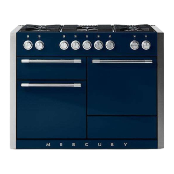
Range overview DocAUS.020-0004 - Overview - 110DF - Elan Fig. 2.1 The 48” dual fuel range (Fig. 2.1) has the following features: Fig. 2.2 5 gas burners including 1 wok burner (Fig. 2.2) A control panel Glide Out Broiler System™ Main multi-function oven Interlocking cast iron grates Convection oven... -
Page 12: Wok Burner
When you release the control knob, if the burner goes out, Fig. 2.4 the Flame Supervision Device (FSD) has not been bypassed. Turn the control knob to the OFF position and wait for one minute before you try again, this time making sure to hold in the control knob for slightly longer. -
Page 13: Igniting Cooktop Burners Without Electricity
We recommend a minimum wok pan of 13 3/16” (335 mm). The Fig. 2.12 cradle should be used on the wok burner only. When you fit the cradle, make sure that it is supported properly on a burner grate and the wok is sitting level in the cradle (Fig. 2.12). The cradle will get very hot in use –... -
Page 14: Ovens
Ovens Convection This function operates the fan and the heating Please refer to (Fig. 2.1). element around it. An even heat is produced References to ‘left-hand’ and ‘right-hand’ ovens apply as throughout the oven, allowing you to cook large viewed from the front of the appliance. amounts quickly. -
Page 15: Convection Oven
Conventional (Top and Base Heat) Function This function combines the heat from the top and Defrost To thaw small items in the oven without heat. base elements. It is particularly suitable for roasting and baking pastry, cakes and biscuits. A full cooking function, even heat throughout, Convection great for baking. -
Page 16: Operating The Ovens
Operating the ovens Fig. 2.14 Operating the multi-function oven The multi-function oven has two controls: a function selector and a temperature setting knob (Fig. 2.14). °F Turn the function selector control to a cooking function. Fig. 2.15 shows the control set for convectional oven cooking. - Page 17 Flammable materials may explode and result in fire Fig. 2.22 or property damage. To fit the telescopic shelf runners With the runner arm in the closed position locate the opening of the upper rear slot onto the side support (Fig. 2.22). DO NOT locate any further than the opening at this point.
-
Page 18: Using The Glide-Out Broiler
Using the Glide-out Broiler™ DocAUS.020-0004 - Overview - 110DF - Elan Fig. 3.1 Fig. 3.2 Nearest to the element Middle High Middle Low Furthest from the element Four grill height positions refer to Fig. 3.5 Fig. 3.3 Fig. 3.4 To switch on both element To switch on the right half element Four grill height positions Fig. -
Page 19: Cooking Tips
Cooking tips Cooking with a multi-function oven Fig. 4.1 REMEMBER: not all modes are suitable for all food types. The oven cooking times given are intended as a guide only. General oven tips ArtNo.050-0019 - Albertine SC - Shelf position The wire racks should always be pushed firmly to the back of the oven. -
Page 20: Cooking Table
Cooking table DocNo. 031-0004 - Cooking table - electric & fan single cavity The oven control settings and cooking times given in the table below are intended to be used as a guide only. Individual tastes may require the temperature to be altered to provide a preferred result. ArtNo.050-0019 - Albertine SC Food is cooked at lower temperature in a fan oven than in a conventional oven. -
Page 21: Cleaning Your Range
Cleaning your range Essential information Fig. 6.1 Before thorough cleaning, turn off the circuit breaker. Allow the range to cool. After cleaning remember to switch on the circuit breaker before using the range. ArtNo.311-0030 - Burner head fitting NEVER use paint solvents, caustic cleaners, ... - Page 22 Stainless steel main top Fig. 6.4 Lift away pots or pans from main top. Remove grates from spillage area and carefully place in a sink of warm soapy water. Wipe loose debris from main top. Avoid using any abrasive cleaners including cream cleaners on brushed stainless steel surfaces.
- Page 23 Glide-out broiler™ Fig. 6.5 Before you remove any of the broiler parts for cleaning, make sure that they are cool, or use oven gloves. Wash the broiler pan, trivet and broiler tray in hot soapy water. Alternatively, wash the broiler pan in a dishwasher. After broilling meats or any foods that soil, leave to soak for a few minutes in the sink immediately after use.
- Page 24 Cleaning table Cleaners listed (Table 6.1) are available from supermarkets or on line. For enamelled surfaces use a cleaner that is approved for use on vitreous enamel. Regular cleaning is recommended. For easier cleaning, wipe up any spillages immediately. Cooktop Part Finish Recommended Cleaning Method...
-
Page 25: Troubleshooting
Troubleshooting All servicing and repairs must be carried out by a We DO NOT recommend corrosive or caustic qualified service engineer. cleaners as these may damage your range. Ignition or cooktop burners faulty The knobs get hot when I use the oven, can I avoid this? Is the power on? Yes, this is caused by heat rising from the oven, and heating them up. - Page 26 Oven not coming on Fig. 7.1 Is the power on? If not there may be something wrong with the power supply. Is the range supply on at the circuit breaker? Have you set a cooking function? ArtNo.320-0006b -Mercury oven door hinge adjustment Oven temperature getting hotter as the range gets older If turning the knob down has not worked or only worked for a short time then you may need a new thermostat.
-
Page 27: Installation Instructions
8. Installation Instructions WARNING! If the information in these instructions is not followed exactly, a fire or explosion may result, causing property damage, personal injury or death. DO NOT store or use gasoline or other flammable vapors and liquids in the vicinity of this or any other appliance. - Page 28 The following symbols are related to safety and are used on the product and throughout this manual. Meaning / Description Symbol Meaning / Description Symbol HEAVY WARNING / CAUTION This product is heavy and reference An appropriate safety instruction should be made to the safety should be followed or caution taken if instructions for provisions of lifting a potential hazard exists.
-
Page 29: Service And Parts
If you are still having difficulty, please contact Tech Support at 800.914.4799 or email techsupp@middlebyresidential.com . Please note For warranty information or to register your AGA range, email customersupport@middlebyresidential.com. You may also refer to the warranty document provided with the appliance or contact 888.845.4641 Option 3 . -
Page 30: Installation Safety Instructions
INSTALLATION Check the appliance is electrically safe when you have finished. 10. Installation safety instructions Regulations Improper installation, adjustment, alteration, service or maintenance can cause injury or property Installation of this range must conform with local damage. Refer to this manual. For assistance or codes, or in the absence of local codes, with the additional information, consult a qualified engineer. - Page 31 INSTALLATION Check the appliance is electrically safe when you have finished. Converting to propane gas This appliance is supplied set for natural gas. A conversion kit for Propane gas is supplied with the range (A060048). The conversion must be performed by a qualified LP gas installer.
-
Page 32: Installation
INSTALLATION Check the appliance is electrically safe when you have finished. 11. Installation You will need the following equipment to complete the range Additional materials you may need: installation satisfactorily: Gas line shut-off valve. • Multimeter (for electrical checks). Pipe joint sealant or UL-approved pipe thread tape with Teflon* that resists action of natural and LP gases. - Page 33 INSTALLATION Check the appliance is electrically safe when you have finished. Positioning the range Fig. 11.1 Fig. 11.1, Fig. 11.2 and Fig. 11.3 show the minimum recommended distance from the range to nearby combustible surfaces (see Table 11.1). We recommend a gap of no more than 3/16” (5 mm) (see Table 11.1) either side of the appliance for moving the range.
- Page 34 INSTALLATION Check the appliance is electrically safe when you have finished. The depth of the range is 28 " (723 mm) overall (Fig. 11.4). Fig. 11.4 (1177 mm) If the range is near a corner of the kitchen, a clearance of 3 ½” (90 mm) is required to allow the oven doors to open (723 mm) (Fig.
-
Page 35: Fitting The Flue, Flue Vent And Side Panels
INSTALLATION Check the appliance is electrically safe when you have finished. 12. Fitting the flue, flue vent and side panels Fitting the knobs Checking the parts: Gently push-fit the control knobs onto the spindles. Flue Flue Vent Fitting the flue Remove the four screws from the broiler flue opening (Fig. -
Page 36: Fitting The Cooling Fan Box
INSTALLATION Check the appliance is electrically safe when you have finished. Fitting the cooling fan box Fig. 12.3 Remove the six screws where the cooling fan box will be fixed Fig. 12.3. The shape of the molex plug should match the socket. Gently connect the molex plug to the molex connector socket Fig. -
Page 37: Fitting The Side Panel Rear Retaining Brackets
INSTALLATION Check the appliance is electrically safe when you have finished. Fitting the side panel rear Checking the parts: retaining brackets Side panel rear retaining brackets Side panels A052064 - Right-hand A051761 - Right-hand Located at the bottom left and right rear corner of the A052067 - Left-hand A051759 - Left-hand range, remove the two screws (Fig. -
Page 38: Fitting The Obscuring Trims
INSTALLATION Check the appliance is electrically safe when you have finished. Fitting the obscuring trims Fig. 12.9 Located near the front on each side of the range there are three screws. Loosen the top and bottom screws (Fig. 12.9). Slide the trim onto the screws and tighten to secure. Fitting the side panels Loosen the screw in the flue vent (Fig. -
Page 39: Fitting The Front Mounting Brackets
INSTALLATION Check the appliance is electrically safe when you have finished. Fitting the front mounting Fig. 12.13 brackets Open the right-hand oven door and pull the drawer out to its furthest point. Push the ends of the plastic clips (Fig. 12.13 and Fig. 12.14) to release the catches holding the drawer to the side runners. -
Page 40: Fitting The Bottom Panel (Toe Kick)
INSTALLATION Check the appliance is electrically safe when you have finished. Fig. 12.17 Fitting the bottom panel (toe kick) Side panel Tilt the bottom of the panel slightly to locate the lower Toe kick Bottom panel slots onto the washers (Fig. 12.17). Now rotate the panel to fit over the pins (Fig. -
Page 41: Fitting The Drawer
INSTALLATION Check the appliance is electrically safe when you have finished. Fitting the drawer Fig. 12.21 To fit the drawer, pull the side rails fully out (Fig. 12.21). Carefully move the drawer back between the rails and rest it on the side rails. At each side, hold the front of the drawer and pull the side rail forward so that the clips click into position, holding the drawer to the side rails (Fig. -
Page 42: Fitting The Restraint Chain And Anti-Tip Device
INSTALLATION Check the appliance is electrically safe when you have finished. Fitting the restraint chain and anti- Fig. 12.23 tip device Restraint chain A range using a flexible gas connector must be secured with a suitable restraint chain and anti-tip device. When fitting the restraint chain it should be kept as short as is practicable and fixed firmly to the rigid pipe at the top, right-hand, rear of the range, when viewed... -
Page 43: Removing The Side Panels
INSTALLATION Check the appliance is electrically safe when you have finished. 13. Removing the side panels DISCONNECT THE ELECTRICAL SUPPLY. Fig. 13.1 You will need the following equipment to remove the side panels: • Cross-head screwdriver • Flat head screwdriver •... -
Page 44: Removing The Side Panels
INSTALLATION Check the appliance is electrically safe when you have finished. Removing the side panels Fig. 13.5 Loosen one screw in the vent (Fig. 13.5). Push forward the side panel so that it moves away from the flue vent and the retaining washer (Fig. 13.6). Inside the top of the side panel top are two tabs. -
Page 45: Gas Connection
INSTALLATION Check the appliance is electrically safe when you have finished. 14. Gas connection Installation of this range must conform with local codes or, in Fig. 14.1 the absence of local codes, with the National Fuel Gas Code, ANSI Z223.1-latest edition. 11 ¼”... - Page 46 INSTALLATION Check the appliance is electrically safe when you have finished. Connect the range to the gas supply Fig. 14.3 Shut off the main gas supply valve before disconnecting the Appliance old range and leave it off until the new hookup has been Flexible connector Adaptor gas inlet...
- Page 47 INSTALLATION Check the appliance is electrically safe when you have finished. When using test pressures greater than ½ psi (3.5 kPa) to pressure test the gas supply system of the residence, disconnect the range and individual shut-off valve from the gas supply piping.
-
Page 48: Electrical Connection
INSTALLATION Check the appliance is electrically safe when you have finished. 15. Electrical connection Have your appliance properly installed and grounded by a qualified technician. The installation must conform with local codes or in the absence of local codes in accordance with the National Fuel Gas Code, ANSI Z223.1/NFPA 54 or, in Canada, the Natural Gas and Propane Installation Code, CSA B149.1 and in addition the National Electrical Code NFPA 70 or the... - Page 49 INSTALLATION Check the appliance is electrically safe when you have finished. Recommended electrical outlet location Fig. 15.1 When connecting using a NEMA 14-50R receptacle, if possible position it so it can be accessed through the opening at the rear of the drawer cavity (Fig. 15.1). Alternate location within the shaded area in (Fig.
-
Page 50: Final Fitting And Checks
INSTALLATION Check the appliance is electrically safe when you have finished. 16. Final fitting and checks Fitting the interlocking grates Fig. 16.1 Please note that the Continuous Grates supports are handed, and may prevent the centre pan supports from fitting correctly. -
Page 51: Circuit Diagram
17. Circuit diagram P026819 P026819 P029549 P033458 P028728 P033458 Code Description Code Description Code Color Blue Broiler Thermostat Right-hand oven thermostat Brown Broiler Controller Right-hand oven switch block Black Broiler Elements Right-hand oven element Orange Left-hand oven thermostat Right-hand oven fan motor Left-hand oven switch block Ignition switches Violet... -
Page 52: Technical Data
18. Technical data INSTALLER: Please leave these instructions with the user. DATA BADGE LOCATION: Inside base drawer of cavity. Remove the drawer (see Overview > Storage for details). COUNTRY OF DESTINATION: USA, Canada, Mexico. Connections ArtNo280-0090 Drawer Cavity & Badges Electric Supply 240 V 60 Hz Electric Rating... - Page 53 AGA warrants the oven heating elements against defects in material or workmanship for an additional two years. These parts will be repaired or replaced at the discretion of AGA without charge, but you pay for labor and transportation subject to the terms and conditions set out below.
- Page 56 By AGA made for : Middleby Residential 4960 Golden Pkwy BLDG 3 Buford, GA 30518 Business 770.932.7282 Fax 770.932.7292 Toll Free Telephone 800.241.9152 www.aga-ranges.com...
Need help?
Do you have a question about the MERCURY AMC48DFSTB and is the answer not in the manual?
Questions and answers